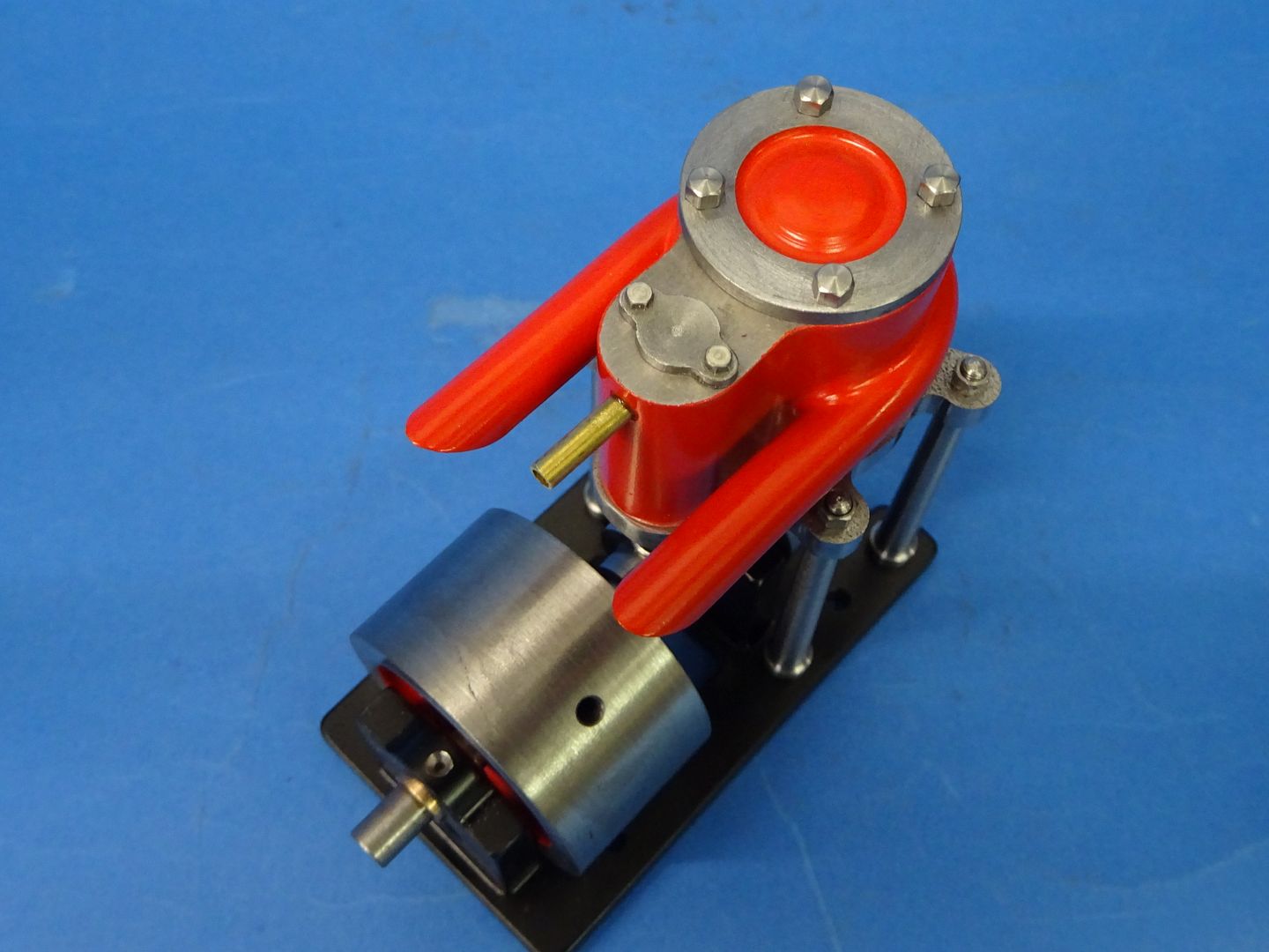
A Lightweight Husky

Home Model Engine Machinist Forum

Help Support Home Model Engine Machinist Forum:

This site may earn a commission from merchant affiliate links, including eBay, Amazon, and others.

Jasonb

Project of the Month Winner!!!
Project of the Month Winner
Joined
Mar 30, 2008
Messages
4,165
Reaction score
1,577
Location
Surrey, UK
I've not posted a build here for very long time but thought why not.

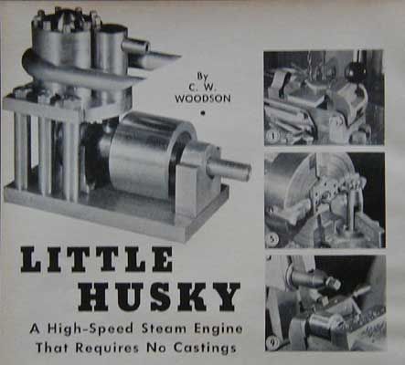
Having recently enjoyed making the Gamages and Bassett Lowke small marine steam engines the next engine to catch my eye while looking for something else was C W Woodson's "Little Husky" as it was a similar type engine and being a Uniflow would allow me to tick off making one of those too. It also had those tempting words "Requires no Castings"
little_husky.jpg


The original article appeared in Popular Science Magazine in 1944 and can be read here

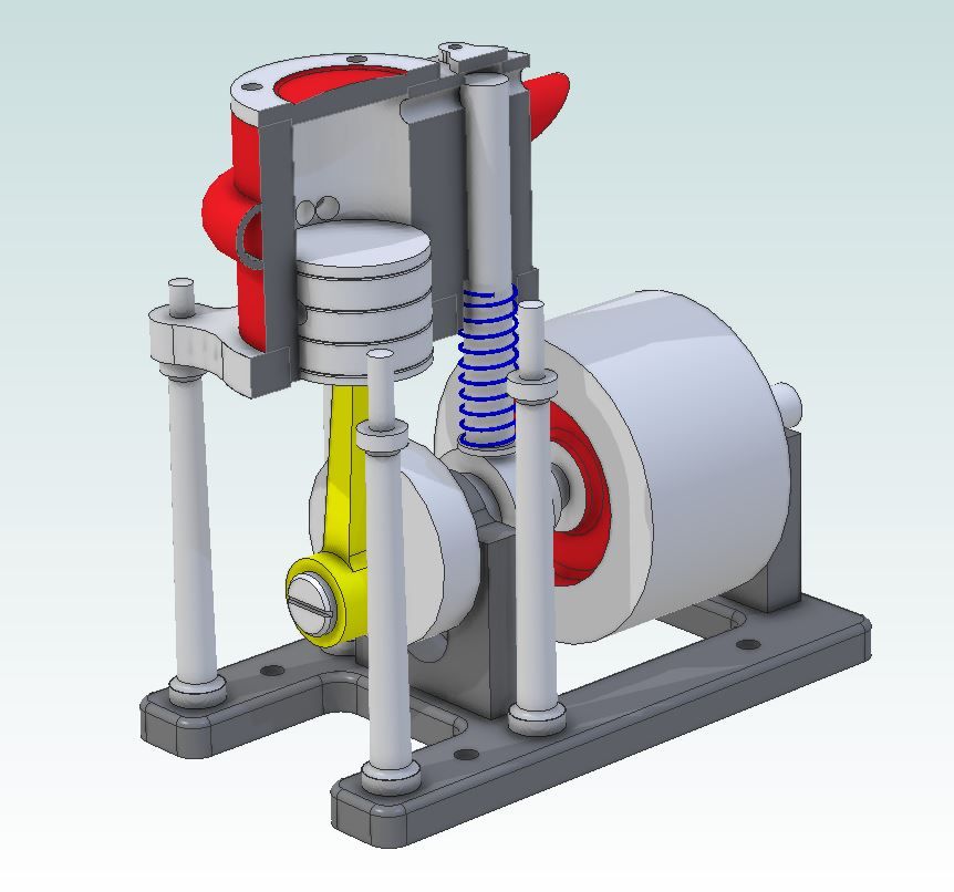
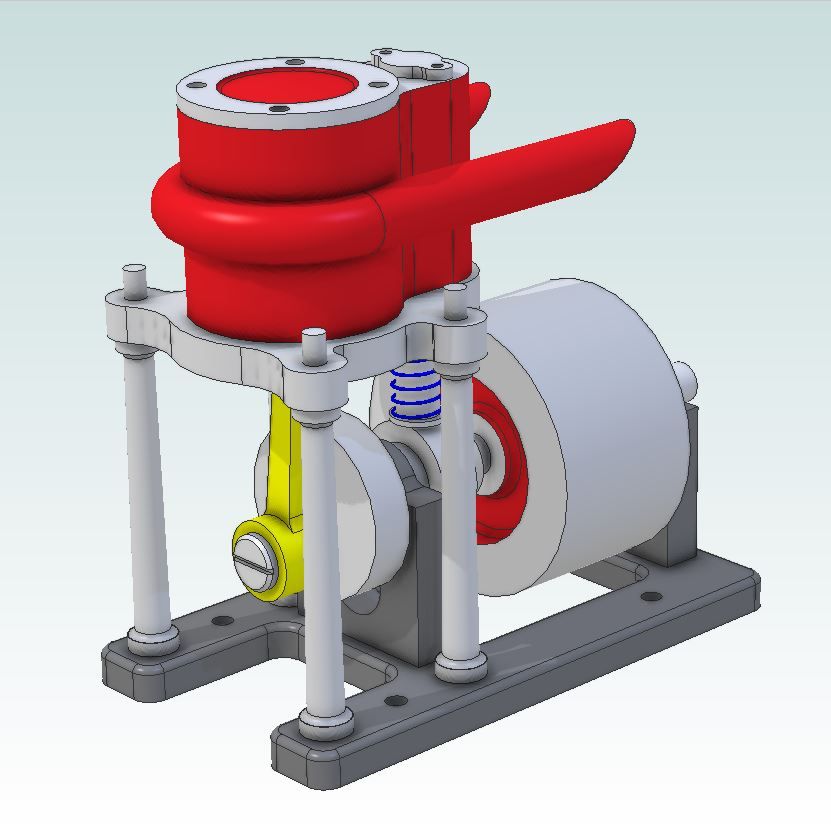
There have been a few of these built on the various forums and even Julius has done a version but they all looked a bit heavy and bulky to my eye. So as well as redrawing it in metric I set about putting this little puppy on a diet and adding a few curves and features while I was at it. The main areas of attention are:

- Entablature and Base. Both made of thinner material and some additional machining to remove excess metal and add some shape particularly to the entablature and I also added some holes so it could be mounted in a hull if needed.

- Columns. Reduced in number from six to four, smaller diameter and also a bit taller with a tapered profile rather than just straight bar.

- Bearing Supports. A couple of holes to reduce bulk and separate bronze bearings added

- Cylinder / Valve chest. Rather than solder two cylinders together I cut this from solid. The valve hole was reamed right through rather than try and ream a blind hole to the end, this also made lapping the valve into the hole easier.

And this is what I came up with after a couple of hours with Alibre
husky_1.JPG


husky_2.JPG
 
  • Like
Reactions: Zeb
I did not take many photos of this build but as there has been some interest shown by Pm and on other forums I'll add a bit of commentary to what images I do have.

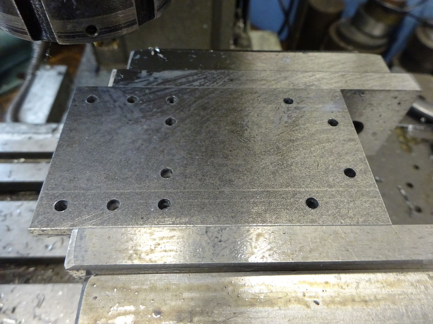
Starting with the base a piece of 5mm plate was milled to the overall size and then the datum located following which the various 3mm holes were drilled.

DSC04378.JPG


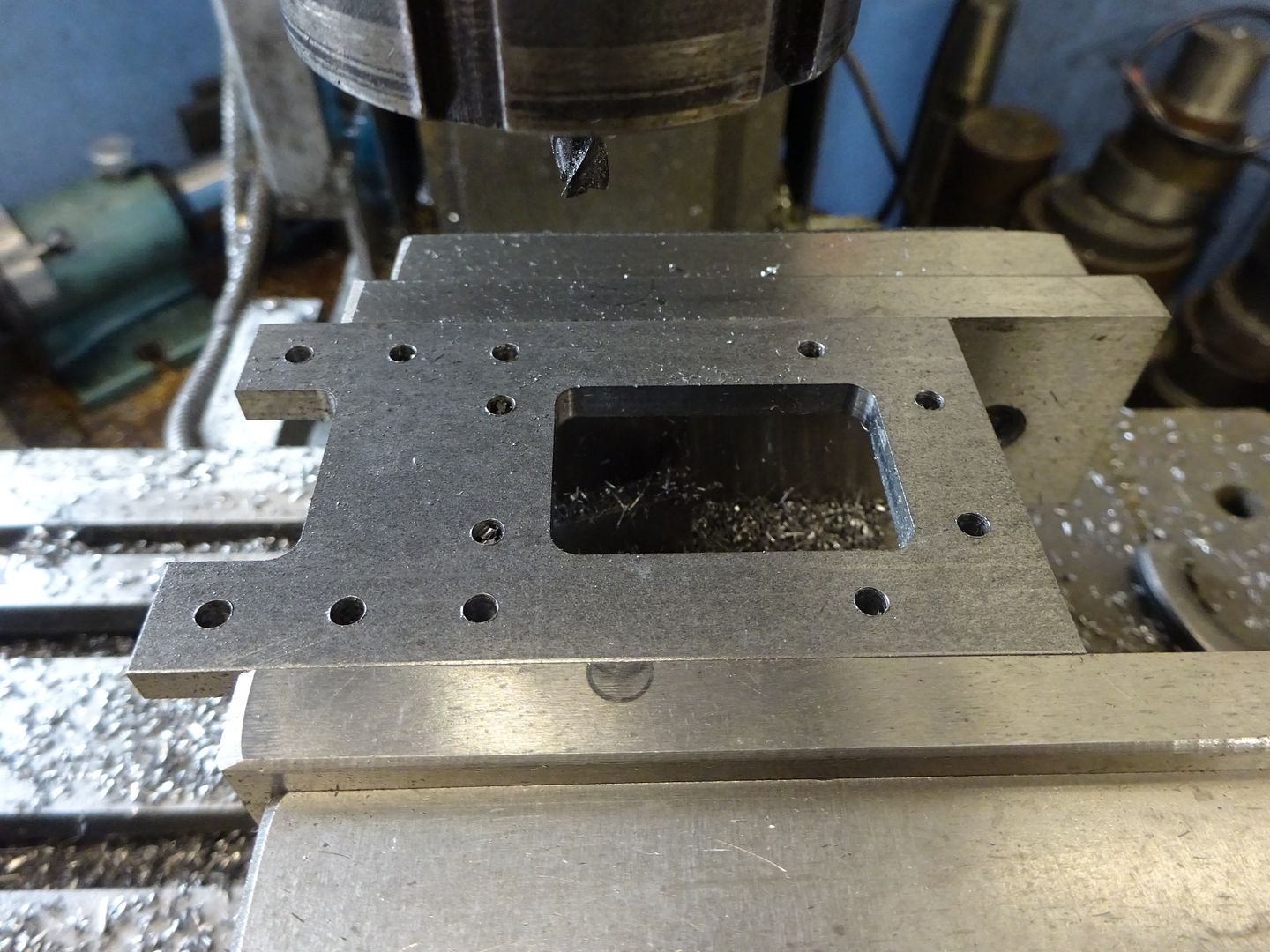
Followed by milling out some of the unwanted material firstly by doing a few passes 0.2mm inside the line and then a full depth pass to remove the last 0.2mm of material. After this the holes for the bearing blocks and columns were countersunk on the underside.

DSC04379.JPG


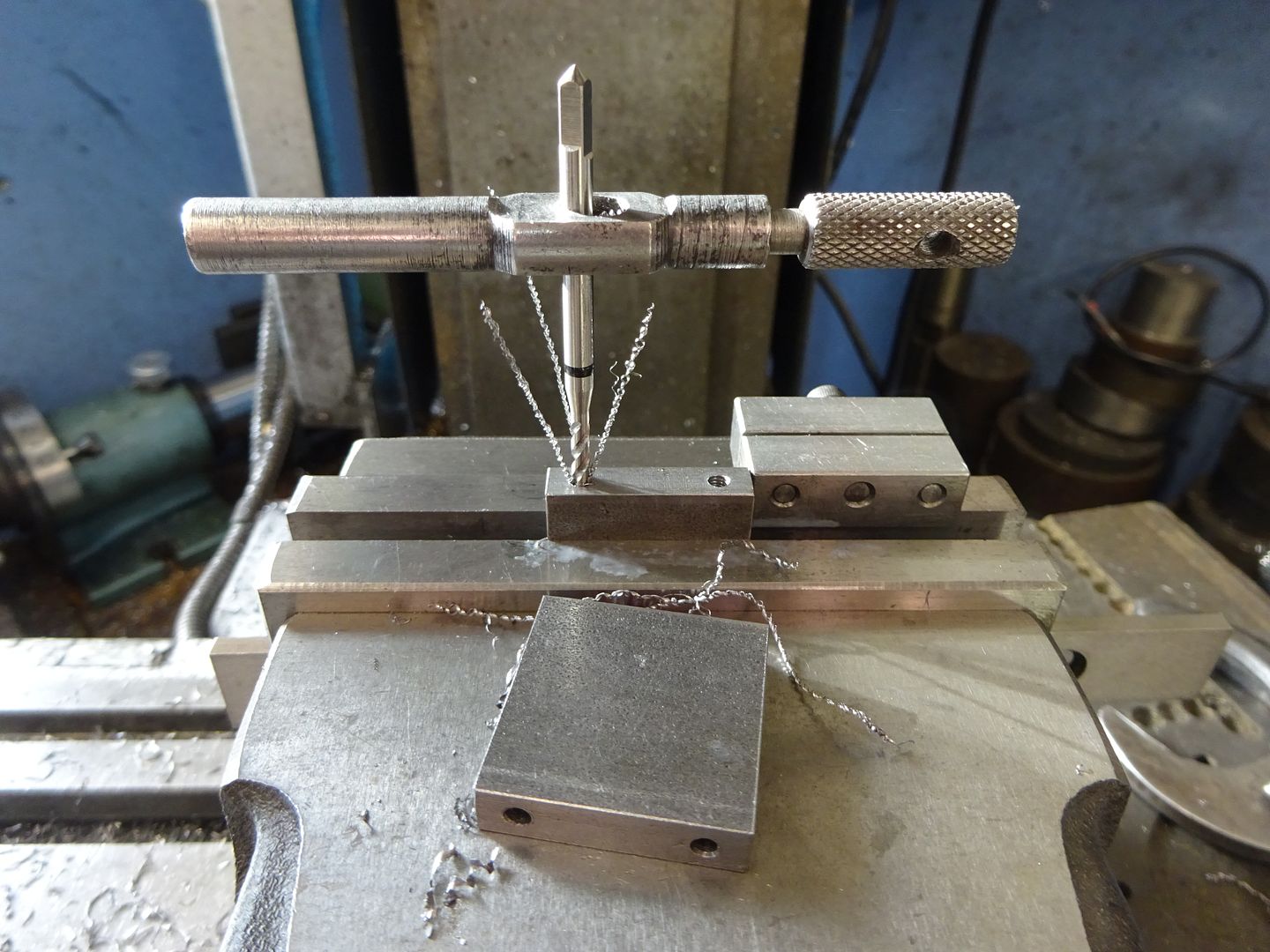
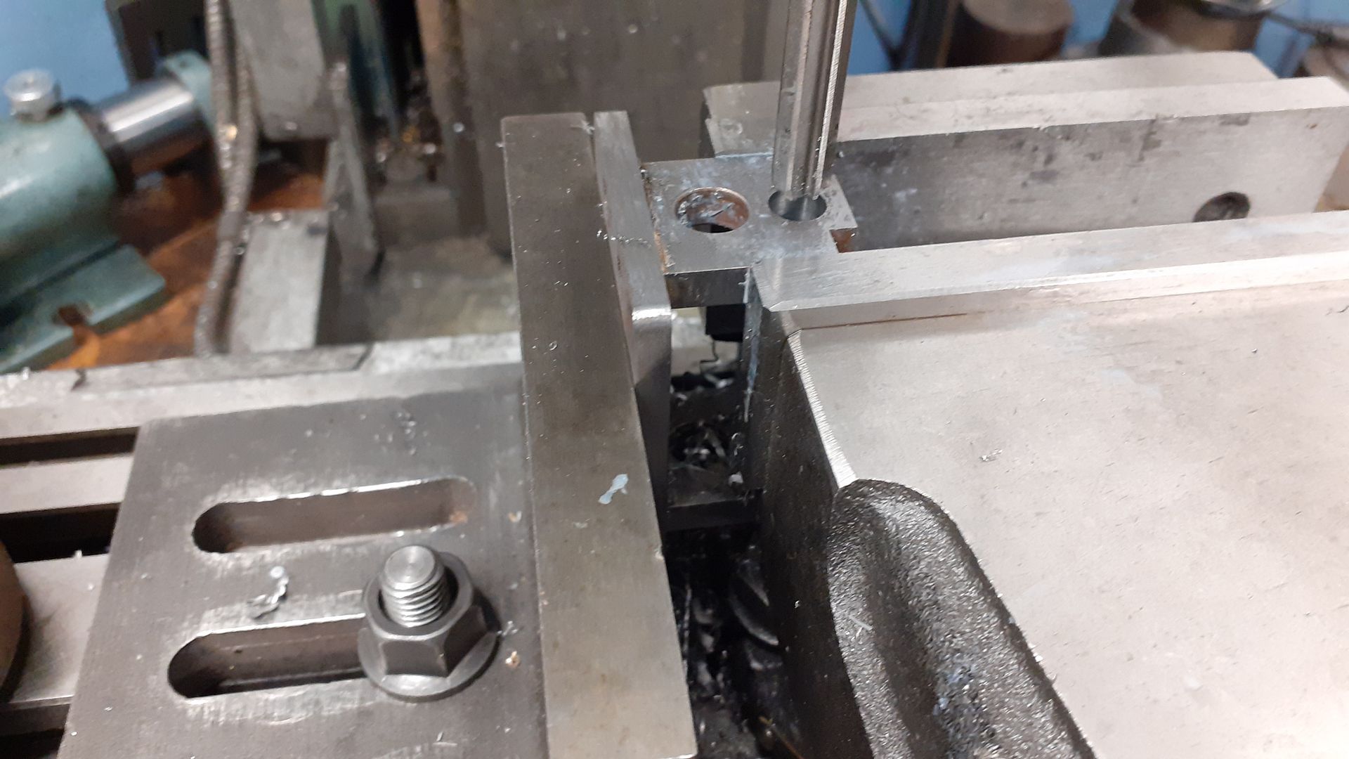
Two pieces of 6mm thick material were squared up and then drilled & tapped M3, the spiral flute tap makes tapping a quick and easy process a syou don't need to keep backing the tap off to break the chips - just let them curl out the top.

DSC04381.JPG


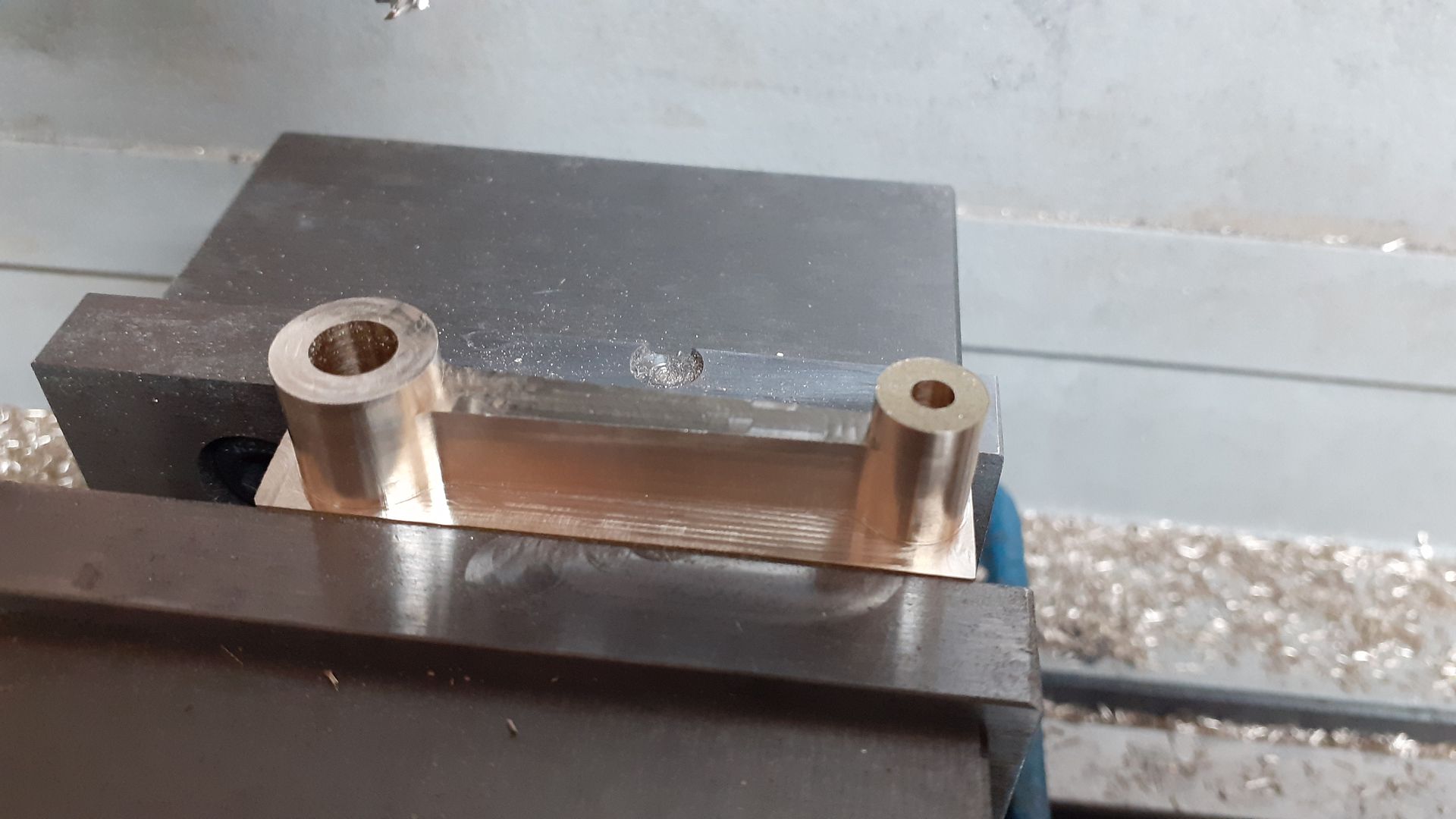
It would be possible to just use a couple of CSK screws to hold the bearing blocks on or add a bit of JBWeld to get a fillet for that cast look but I opted to silver solder. Once out of the pickle the bearing holes were line bored , well actually drilled and reamed with an 8mm machine reamer.

20211112_165140.jpg


I had intended to file the curved top to the bearing caps using a couple of buttons but realised I could do it on the CNC and at just over 60seconds each quicker than I could turn up the buttons. I left the oil holes until the end once the bearings had been Loctited into place drilling both at the same time.

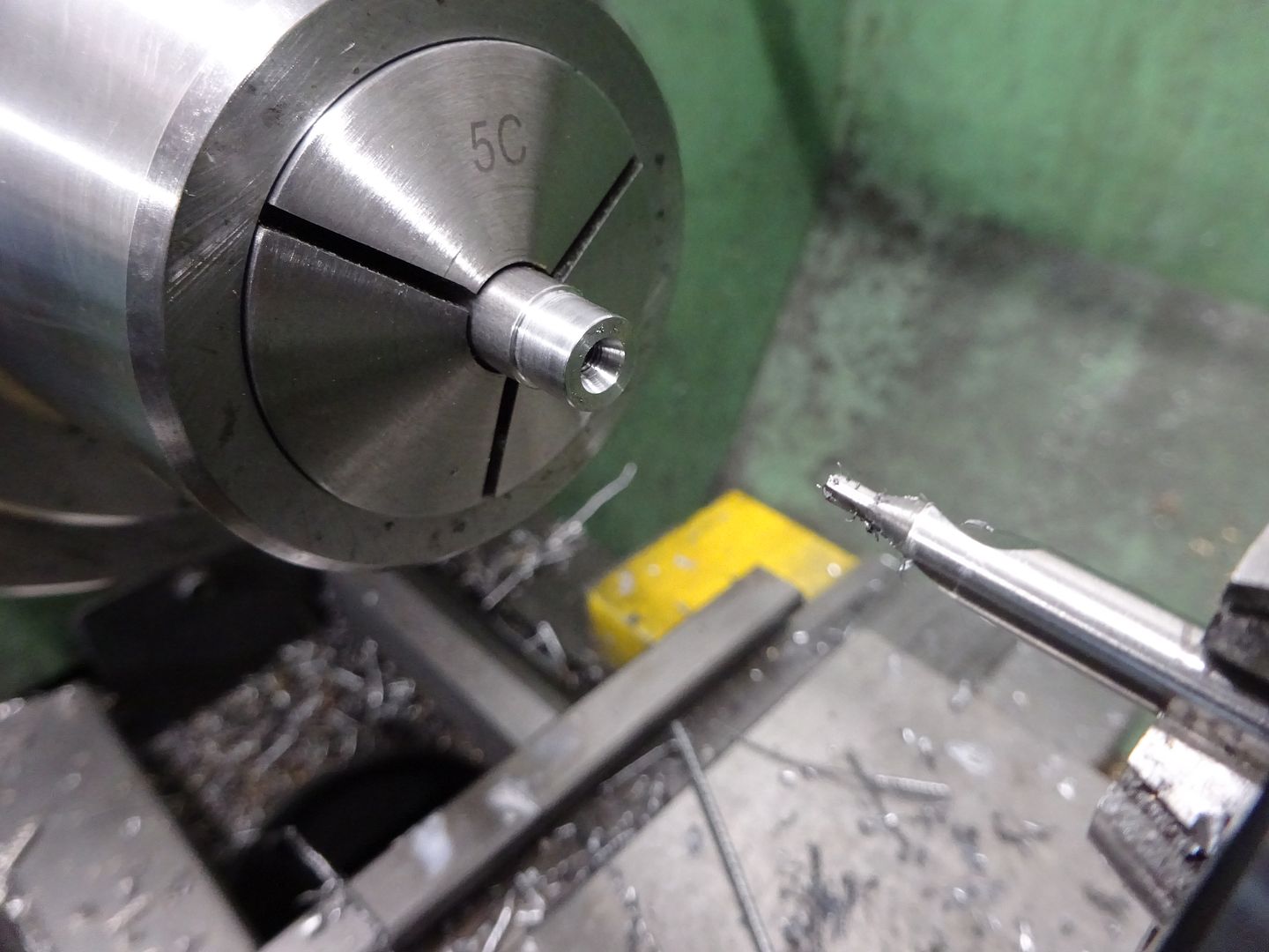
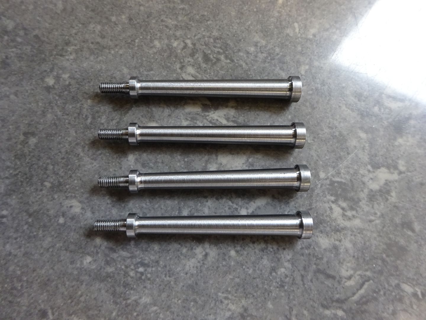
Next up were the columns, after facing four pieces of 8mm stock to the same lengths one end of each was reduced to 7mm dia, drilled and tapped M3 and then a ctr hole drilled for later tailstock support.

DSC04374.JPG


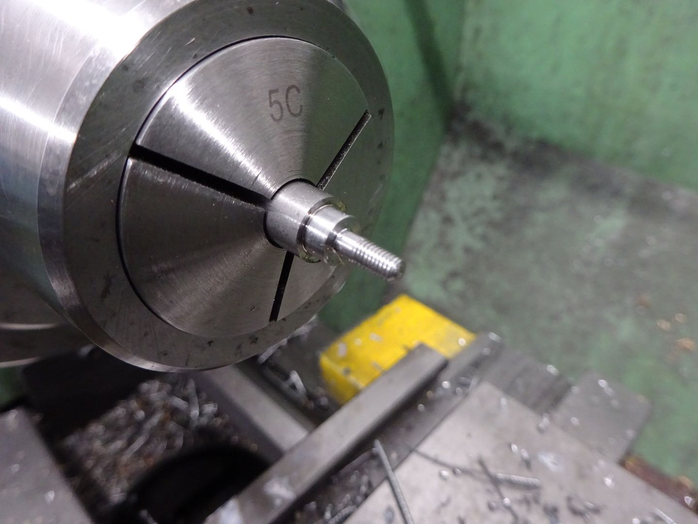
The other end was reduced to 6mm and a 3mm spigot formed and threaded M3 then the end of the exposed thread rounded with a file.

DSC04375.JPG


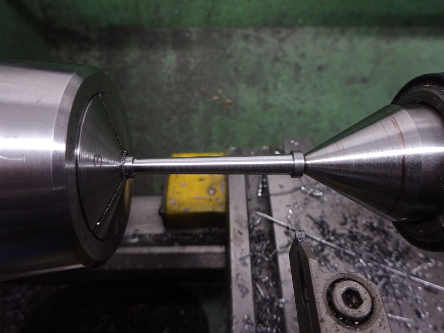
It was then just a case of holding by the 3mm section, adding tailstock support and then setting over the topslide to turn the taper. A 2mm dia grooving insert left a nice 1mm radius fillet at each end of the taper to blend into the flanges.

DSC04376.JPG


DSC04377.JPG


The crank was just a piece of 25mm bar faced off and reamed 6mm then sawn off a bit over length. This was loctited to some 6mm PGMS and once set turned down to the finished 6mm thickness before transferring to the mill for tapping the M4 hole at a throw of 7.5mm. The pin was a simple turning job followed by cutting the saw slot with a slitting saw.
 
I was in two minds as to what to make the cylinder from. Cast iron would have been nice but not so easy to solder the exhaust to it, Bronze and brass would have been easy to solder but it's a bit of a lump and I did not have much suitable in stock (at least that I wanted to cut into) so I ended up going for 230M07 (EN1A) as it's not really any more likely to rust than iron particularly as I'm mostly going to run on air.

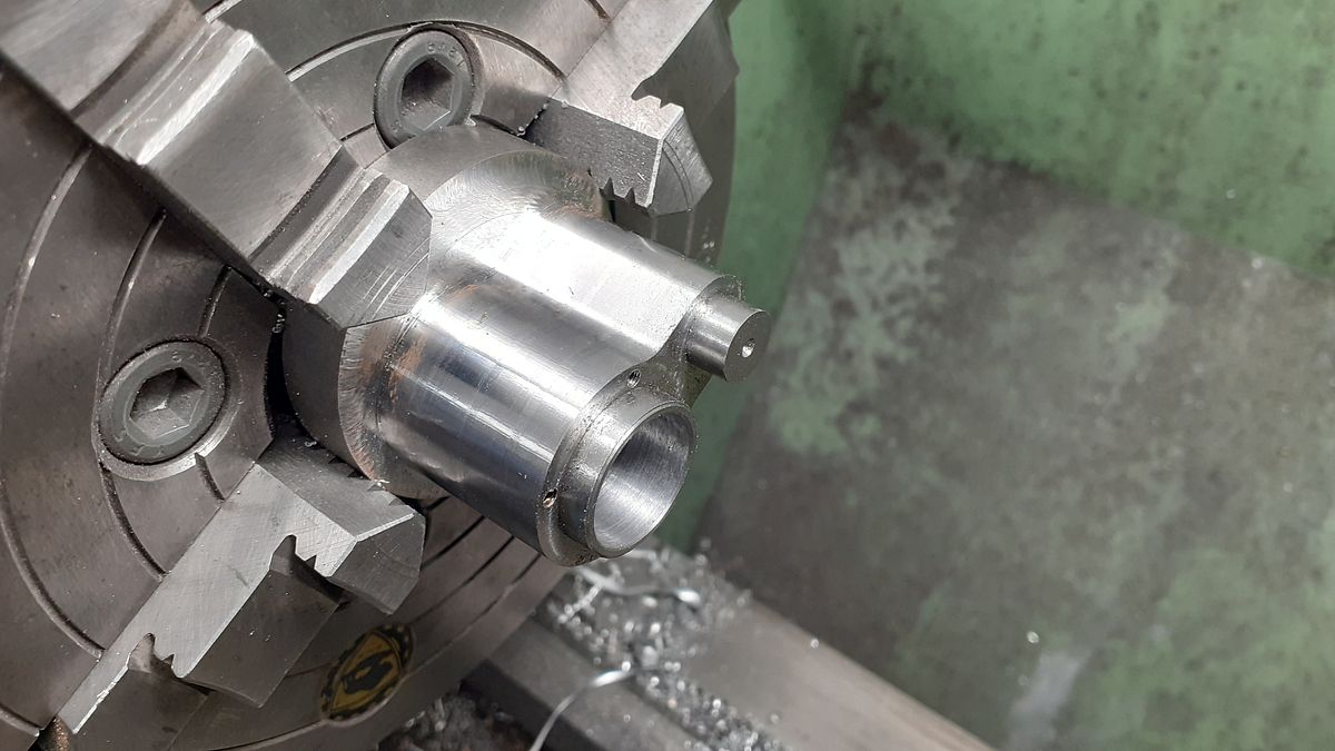
So a piece was sliced off a 2" bar with the trusty Femi band saw, faced each end and then mounted on the CNC. The two ctr drilled holes are to make it easier to locate the bores for machining on the manual machines.


While the mill was switched on I also did the entablature. The fit of the cylinder's spigots was very good into the holes and would have been a good press fit but that was a bit tighter than I wanted so a quick adjustment of the tool diameter in F360 and an extra 0.01mm was taken off the bores which gave a firm push fit.


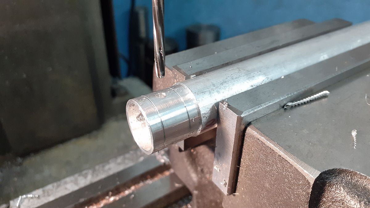
I then held the cylinder in the 4-jaw, clocked the ctr drilled hole true and then drilled and finally bored it out to 18mm

20211124_142436.jpg


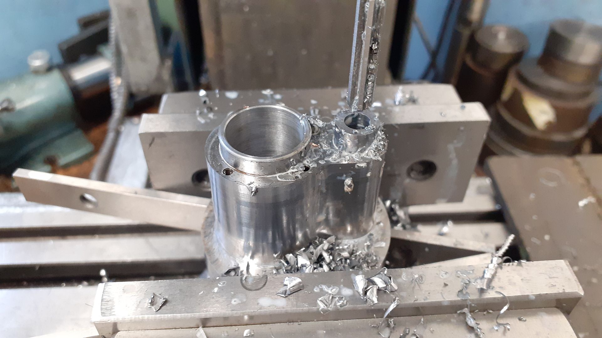
The valve hole was a bit too far off central to make holding in the 4-jaw easy so I used the mill to drill and ream the hole out to 6mm with a machine reamer

20211124_143659.jpg


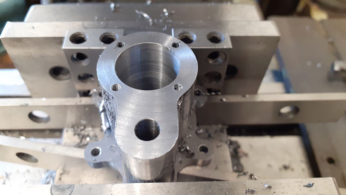
To make sure the cylinder cover holes were lined up correctly I screwed the cylinder to it's entablature and with a couple of 10-20-40 blocks between that and the fixed vice jaw was able to hold it true, locate bore and then drill and tap the four M2.5 holes and later the two M1.6 holes to retain the valve cover plate.

20211125_143459.jpg


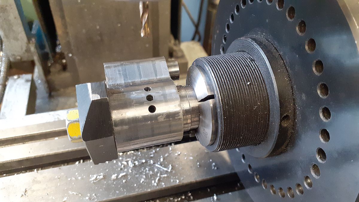
An existing mandrel was quickly altered so the cylinder could be held horizontally in the 5C indexer firstly to drill the inlet passage and then the three exhaust holes each side which are at 20deg spacings.

20211126_141459.jpg


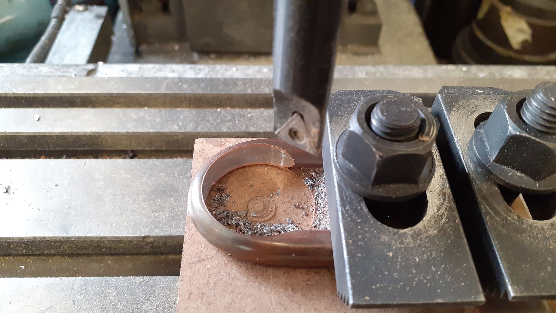
A suitable former was turned from delrin, the 8mm copper tube filled with lead and then bent around the former. I then clamped the "U" shape to a bit of MDF and used the boring head to cut the circular profile so it would slide over the cylinder.

20211127_094816.jpg


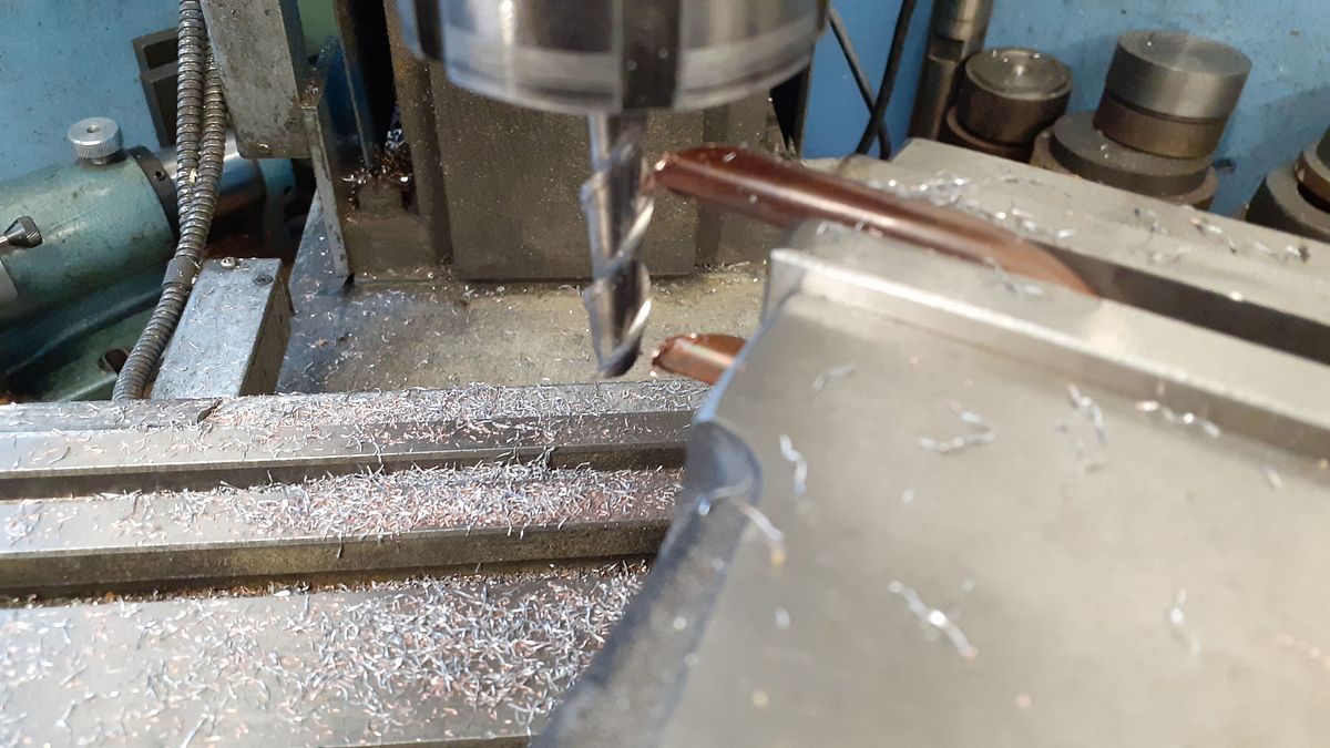
Next the vice was swung round to a pleasing angle and using a long series milling cutter for non-ferrous material both ends were milled to the angle. After this the lead was melted out and the exhaust soldered to the cylinder, I had intended to have the slash cut facing upwards but changed the way I held things for soldering but forgot to turn the pipe up the other way. Still it saved having to paint the inside of the exhaust as it is now just in dark shadow.

20211127_105203.jpg


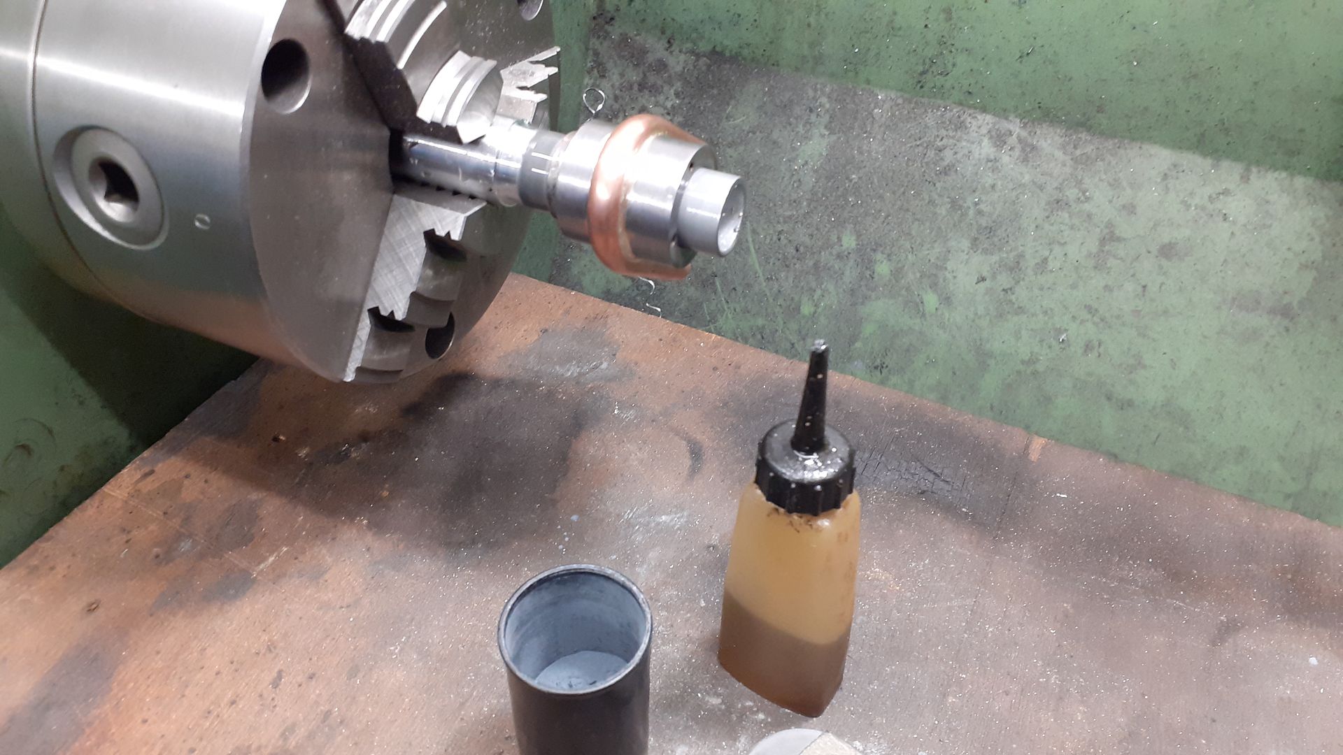
After cleaning up the outside the last thing to do was lap the cylinder on a make shift lap turned from a scrap length of thick wall aluminium tube.

20211127_141228.jpg
 
The piston was fairly straightforward turning and then over to the mill to drill and ream for the 3mm wrist pin before sawing off from the bar and facing the top.

20211127_144310.jpg


The last item I have a photo of is the conrod which was cut from some 1/2" square brass bar on the CNC but I finished the other side on the manual machines.

20211128_091107.jpg


The only other part of any note is the cam which I also did on the CNC but could quite easily be done with a rotary table. The flywheel, valve and valve follower were all basic turning so I did not take any pictures of them being made.

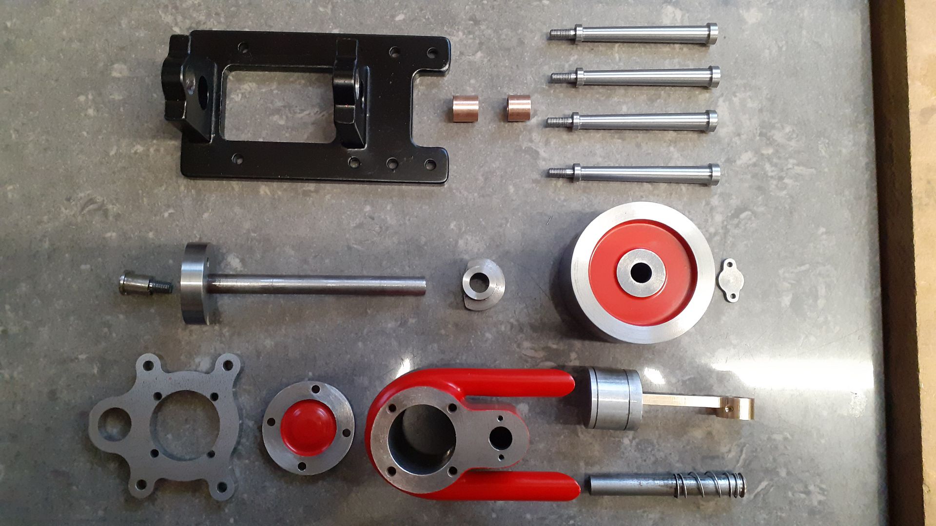
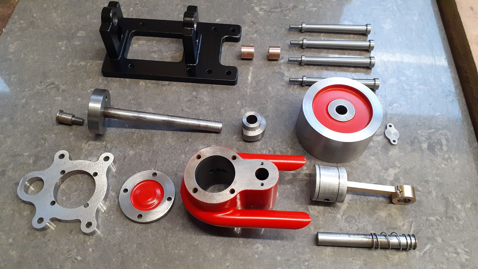
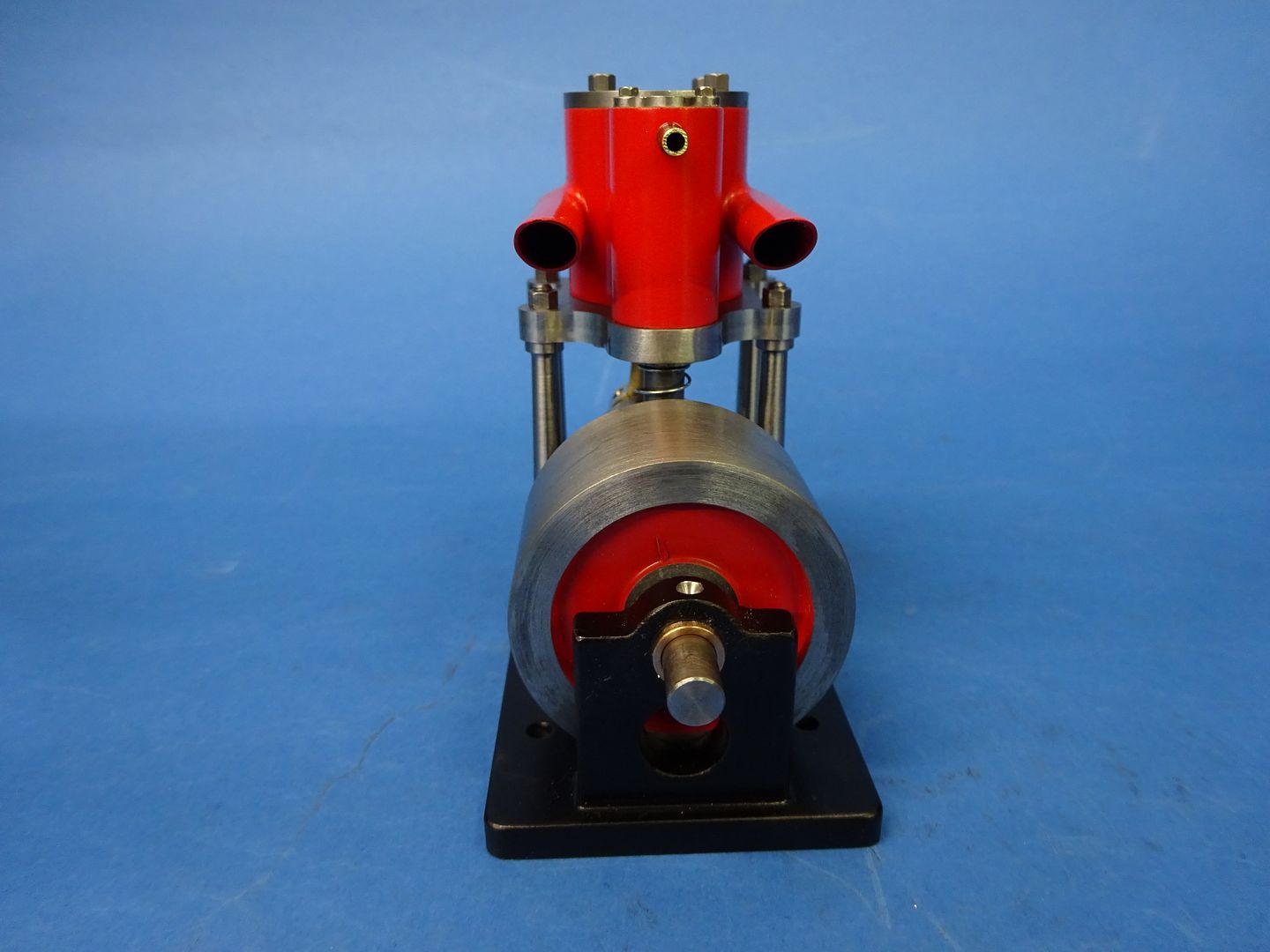
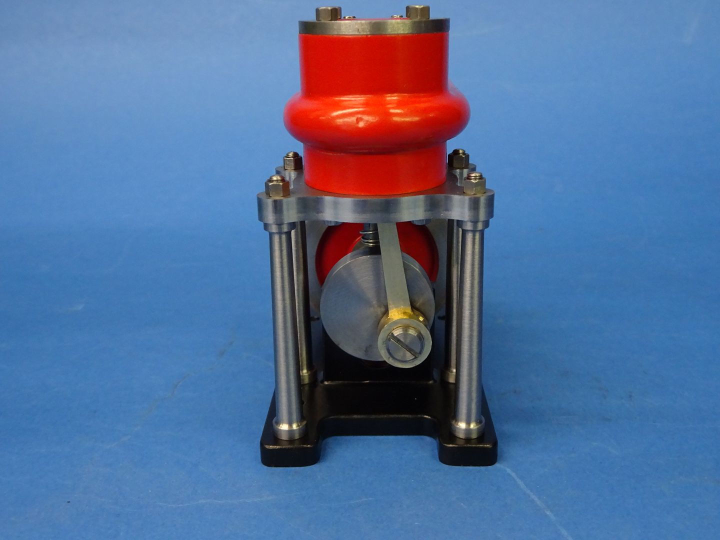
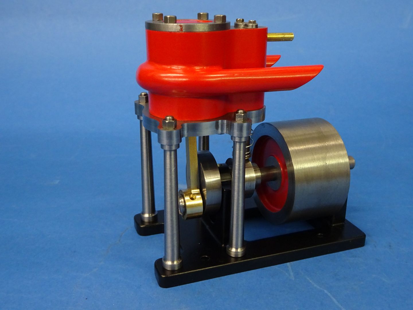
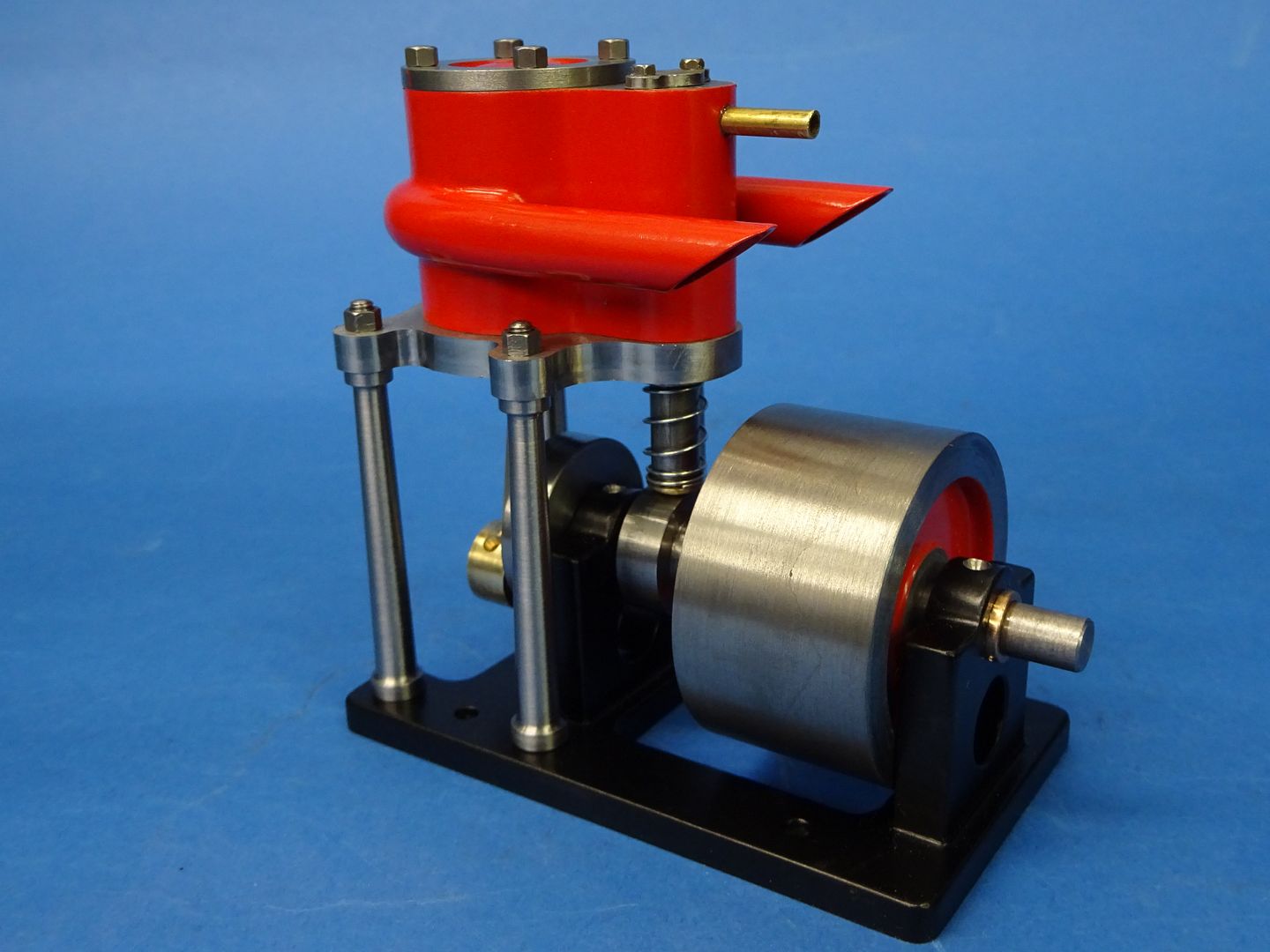
After putting it all together I did need to make a little adjustment of the profile of the cam follower to get the valve to stay open for a longer period and up the pressure from my usual less than 10psi the engine was off and running with a good flick of the flywheel. It was then stripped for painting. As you can see there are not that many parts to this one which makes these little engines a nice change from the longer more complex builds.

20211204_082734.jpg


20211204_082743.jpg


And this is what they go together like

DSC04387.JPG


DSC04391.JPG


DSC04392.JPG


DSC04393.JPG


DSC04395.JPG


DSC04395.JPG


Running on about 30psi (note the balloning silicon tube) which it seemed to need to be able to get the piston back up to TDC. It is quite lively if not clamped down so could probably do with the plain disc crank web being shaped to add some counterbalance and the piston and conrod could also be lightened a bit if needed. 1600rpm Tacho reading if you can wait until the end.


Latest posts

Back
Top