You are using an out of date browser. It may not display this or other websites correctly.
You should upgrade or use an alternative browser.
You should upgrade or use an alternative browser.
A different opposed piston engine---
- Thread starter Brian Rupnow
- Start date

Help Support Home Model Engine Machinist Forum:
This site may earn a commission from merchant affiliate
links, including eBay, Amazon, and others.
No---The law states that all fish huts and debris must be off the ice by the end of March (or something like that), and woe betide anybody who lets their junk fall through into the water when the ice goes out. Heavy duty environmental fines, permanent suspension of fishing license, emasculation and beheading. Its got kinda crazy here in Ontario in the last 15 years.Brian,
So that means the ice fishermen start clearing off the ice on April 22 and the rest fall through on the 23rd.
Art
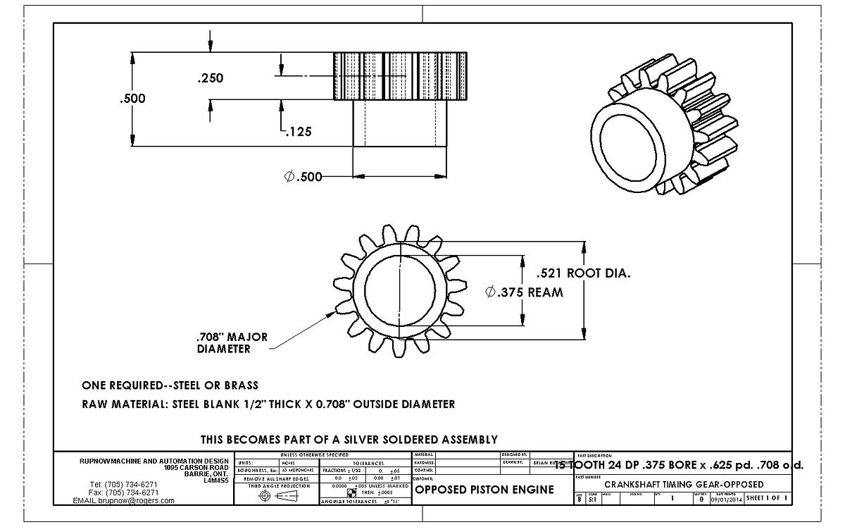
Does anybody know of a reason not to build the large timing gear out of grey cast iron? I have lots of short pieces of 1.6" diameter grey cast iron left over from making pistons and cylinders but I don't have any steel large enough in diameter (1.33").

$154.75 ($1.38 / oz)
Replacement Combustion Chamber Kit, Burnham V8 and V8H, 1-6 Sec, 108136-01, 1129
Plumbing Planet

$94.99
$109.99
AHS Woodmaster 4400 Maintenance Kit for Outdoor Wood Boiler Treatment
Alternative Heating & Supplies

$426.53
DM14 Engine Build Kit, Metal Engine Build Model Great Metal Material for Engineer for Factory
Easoger Official

$40.02
$49.99
Becker CAD 12 3D - professional CAD software for 2D + 3D design and modelling - for 3 PCs - 100% compatible with AutoCAD
momox Shop

$188.98
TM NEXDYNAMI RE41157 Water Pump Compatible With/Replacement For/John Deere 6200 7400 6300 6600 6500 6400 7220 7600 7200 RE41157
VIVID MARKET CORPORATION

$99.99
AHS Outdoor Wood Boiler Yearly Maintenance Kit with Water Treatment - ProTech 300 & Test Kit
Alternative Heating & Supplies

$29.95
Competition Engine Building: Advanced Engine Design and Assembly Techniques (Pro Series)
Amazon.com Services LLC

$39.99
$49.99
Sunnytech Low Temperature Stirling Engine Motor Steam Heat Education Model Toy Kit For mechanical skills (LT001)
stirlingtechonline

$109.99
AmTech300 - Boiler Treatment Professional Strength (Rust Inhibitor For Outdoor Wood Boilers)
Alternative Heating & Supplies

$649.00
$699.00
FoxAlien Masuter Pro CNC Router Machine, Upgraded 3-Axis Engraving All-Metal Milling Machine for Wood Acrylic MDF Nylon Carving Cutting
FoxAlien Official
Fluffy
Well-Known Member
G'Day Brian,
I have made a set of back gears for my lathe from extruded grey cast iron (80, 40, 30, & 25 teeth x 1.5 module) which have been in use for some time now & have not given any problems. They create far less noise than the poorly cut original gears.
The large timing gear (56 tooth, 24 DP shown in attached image) on my Bonza hit & miss was made from the same material & it runs without problems.
I hope this is of some help.
I have been away for a while & have only just read all of the posts re your opposed piston engine. Very well done Brian, it looks great & I look forward to here it running.
Regards,
Don.

Thank you Fluffy. I will try the cast iron and see how it works.---Brian
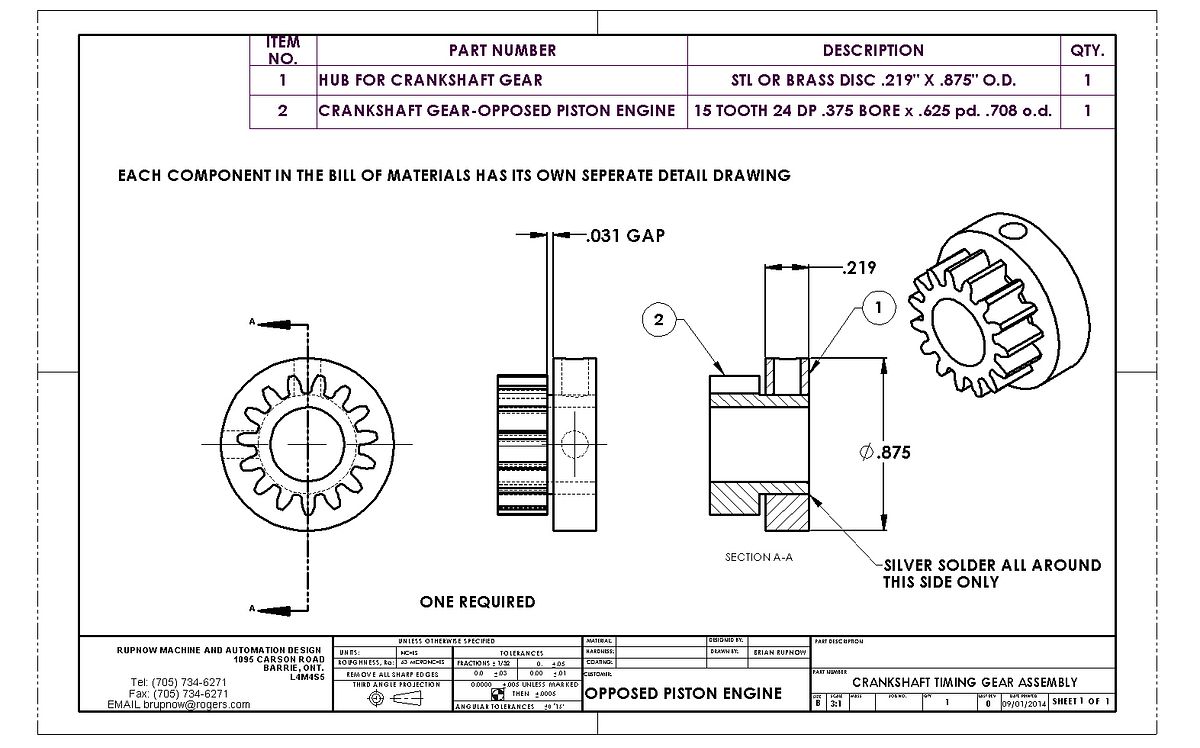
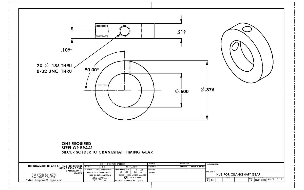
What did I do today??--Well--Not that much really. The round piece laying down has the outer diameter of the crankshaft gear turned on the end of it, and the collar which gets silver soldered to it after the teeth are cut is setting on the end of it. The piece which is setting on end with the purple layout dye on it is going to become my "bolt on" cam. it will be going up on the rotary table tomorrow. I think I will be bold and turn the camshaft gear from grey cast iron.
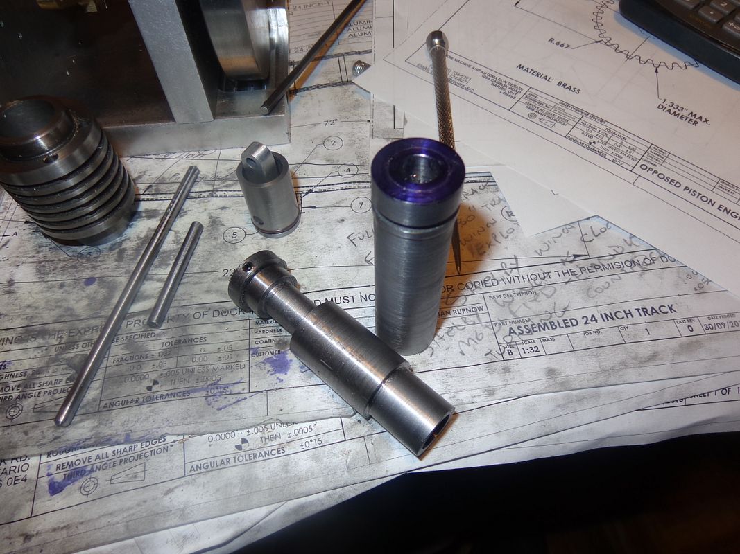

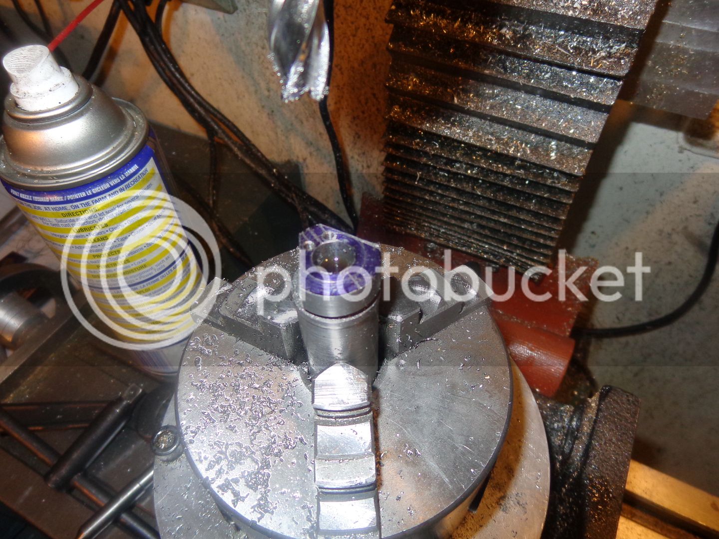
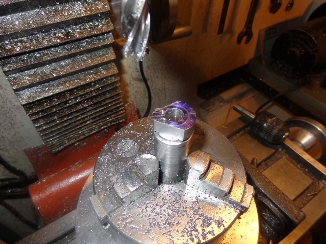
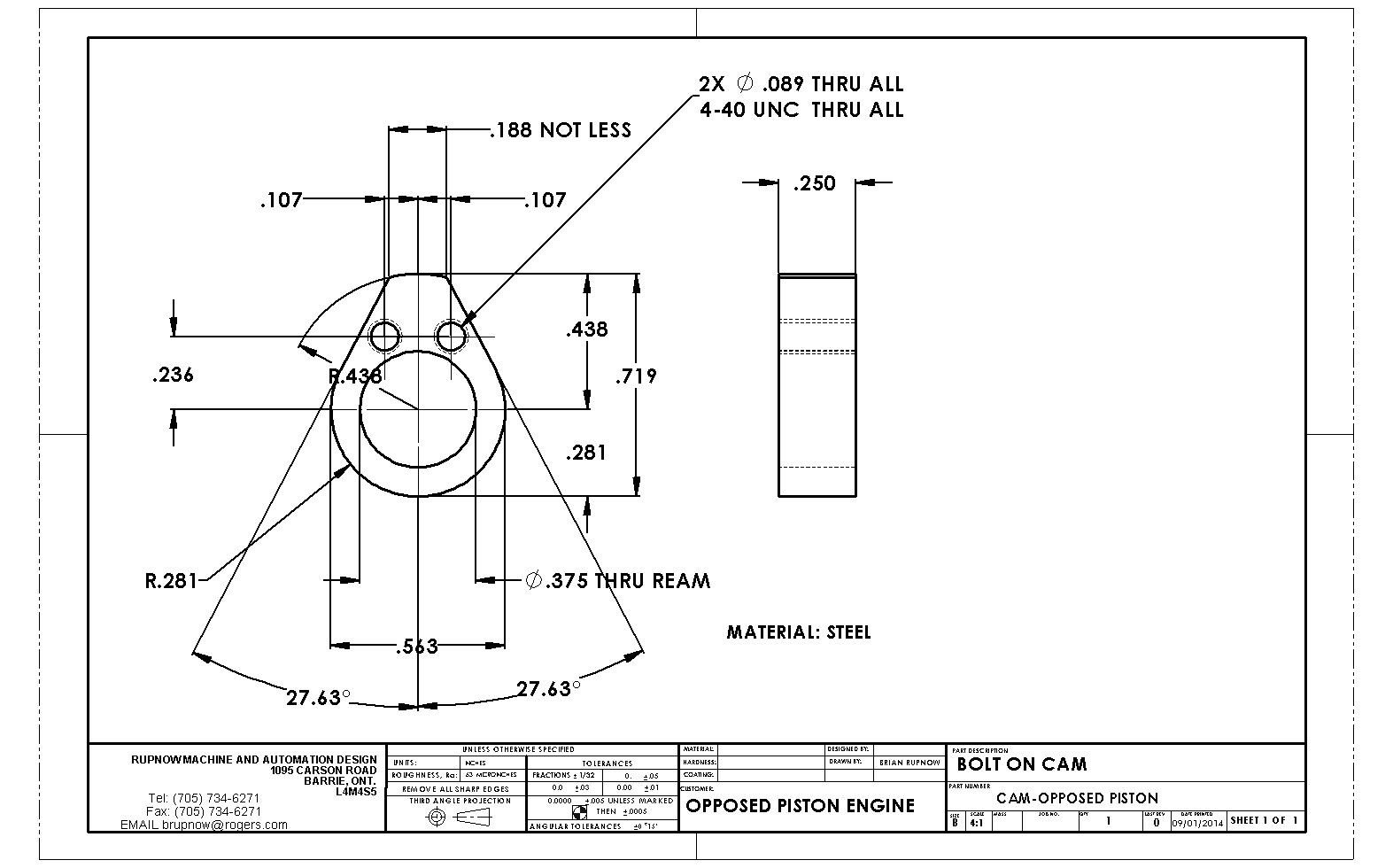
Today we see the simple way to make a cam. This is a cam with straight line flanks, and it works very well in any low speed i.c. engine. If you want to see an excellent video on making a cam with "rounded" flanks, search for the excellent video posted by Chuck Fellows. In yesterdays post, you seen the short piece of shaft standing on end with purple layout dye on it. If you look close you can even see the base circle of the cam scribed on the end of it. I put it in the 3 jaw chuck on my rotary table and centered it under the guill. I decided at that point to use the dials and move things around to drill and tap the two #4-40 holes, and then recentered the part under the quill. Then by inserting a pointer in the quill chuck, I moved the table right and then left 0.094" and scribed two lines, equally about center, 3/16" apart. I then used my scriber and a straight edge to connect the lines to the previously inscribed circle.Then I rotated the rotary table until the scribed "flank" lines were parallel to the "x" travel of the mill. Then it was simply of milling to the required depth plus a bit more on each side. Once both sides were milled, I then used the rotary table to mill away the remaining stock to final shape. Then I took the part over to the lathe and parted off the finished cam.
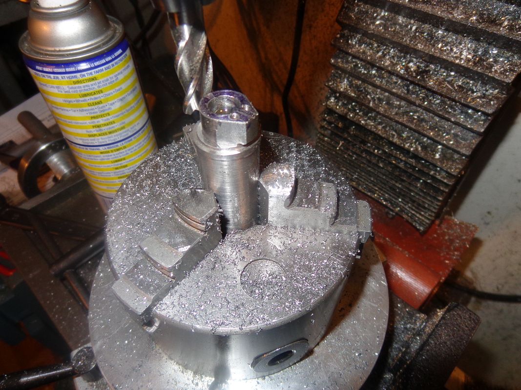
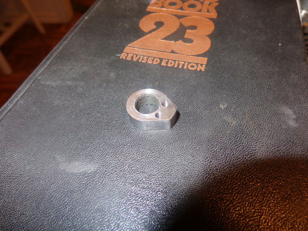


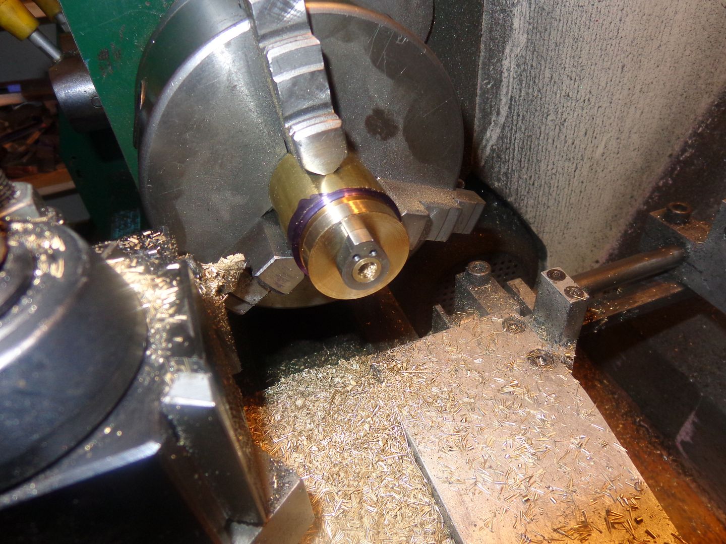
CURSE!! SWEAR!! STAMP FEET!!!--cast iron isn't going to do it for me!! It might make a good gear with a flat face on both sides. It does not work well with the 3/8" diameter protrusion on one side. After 30 minutes of machining, I was just cleaning up the o.d. of the 3/8" diameter x 1/4" long "spigot" that the cam slips over when the whole damn spigot popped off, clean as a whistle. Now I will go buy some cold rolled steel.

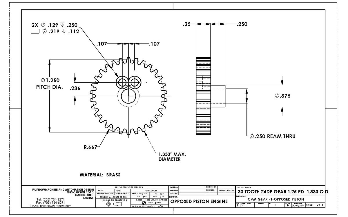
It was probably my fault. I put the .25 bore in the gear first, then was turning the tit down to 3/8" diameter as per the drawing. I find that cast iron eats up HSS tooling very rapidly, so I was using a carbide. If you let carbide get a bit dull, it puts a lot of pressure on what you are cutting. It was more a matter of my questionable machining talent than a fault of the cast iron. I realized after my last post that this gear is turning on a stationary steel shaft, so I couldn't really make it from steel or it would gall. I dipped into the Rupnow fortune and bought 3" of 1.5" diameter brass for $15.--That will make a good gear and will turn without galling on the mild steel shaft.
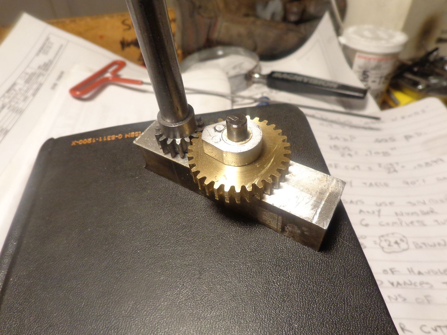
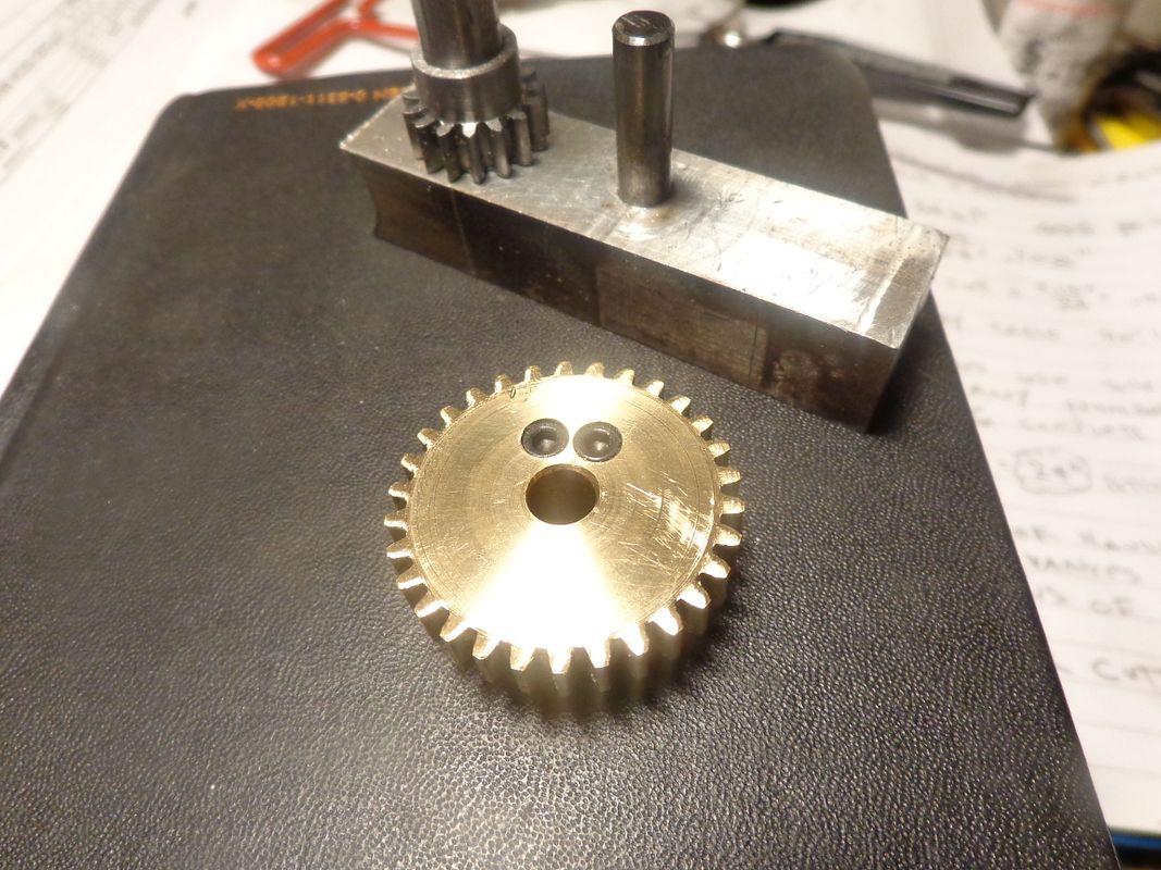
So---Today we have a set of timing gears, with bolt on cam. They are set up in a test block in the picture so that I can confirm to myself that they do mesh properly, and they seem to be fine. It's hard to see that the cam is bolted on, so I've included a pic of the back side of the cam gear, where the heads of the two #4-40 shcs. are visible.


robcas631
Well-Known Member
That is an awesome design!
robcas631
Well-Known Member
Brian...So this is a new concept?
- Joined
- Aug 16, 2013
- Messages
- 1,057
- Reaction score
- 799
Hi Brian. Im no engineer. Ive only built a few steam/air engines. And all I know about small IC engines is tuning up my lawn mower in the spring. That said. Following this thread and looking at this thing its going to sound *****in!
Robcas--No, its not a new concept. In fact, its been around for quite a while . Do a search for "opposed piston engines"--You'll be surprised. I just thought it would make a very interesting model.---Brian
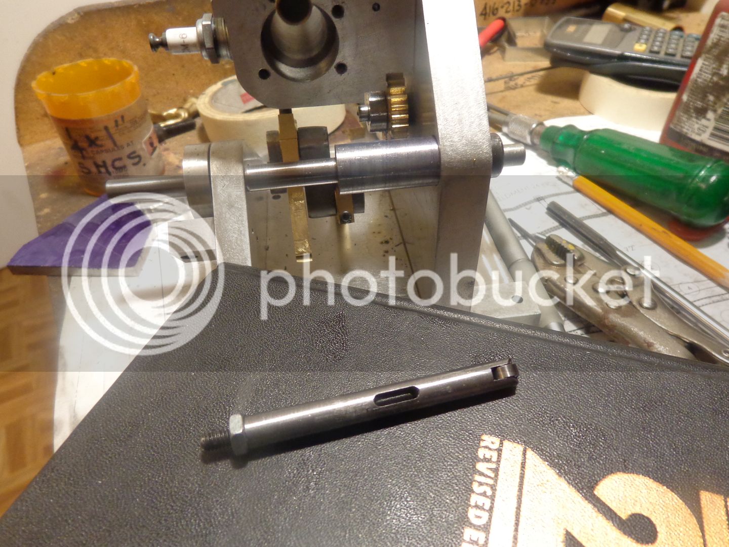
This is kind of a "double duty" picture. In the foreground, laying on the book is my exhaust valve pushrod with the 1/4" diameter x 0.110 wide router bearing fitted into a slot in the end, with a 0.093" diameter axle. I made the pushrod 9/32" diameter so it could be inserted down thru the hole it rides in from the top of the engine. You can also see the .093" wide slot in the pushrod, which lets it travel up and down but not turn crosswise. There is a matching .093" diameter hole which can be seen just at the top of the center section in the background, which a .093" diameter cold rolled rod fits through to keep the pushrod from turning and getting the wheel out of alignment. In the back ground you can see the brass cam gear with the steel bolted on cam setting in place on the engine.

Similar threads
- Replies
- 89
- Views
- 10K
- Replies
- 509
- Views
- 63K
- Replies
- 22
- Views
- 1K




![MeshMagic 3D Free 3D Modeling Software [Download]](https://m.media-amazon.com/images/I/B1U+p8ewjGS._SL500_.png)


