
You are using an out of date browser. It may not display this or other websites correctly.
You should upgrade or use an alternative browser.
You should upgrade or use an alternative browser.
3cc Diesel - My first ICE
- Thread starter Maryak
- Start date


Help Support Home Model Engine Machinist Forum:
This site may earn a commission from merchant affiliate
links, including eBay, Amazon, and others.

SERCEFLYER
Member
- Joined
- Oct 1, 2008
- Messages
- 24
- Reaction score
- 0
Bob,
I'm happy to hear that the Mrs. is doing better. Best wishes.
George
I'm happy to hear that the Mrs. is doing better. Best wishes.
George
Maryak
Well-Known Member
- Joined
- Sep 12, 2008
- Messages
- 4,990
- Reaction score
- 77
First up, thanks guys for your support with Galina. After a restful night she is doing fine and managed to give our credit card a bashing today :") : ::bow: :bow: :bow:
: ::bow: :bow: :bow:
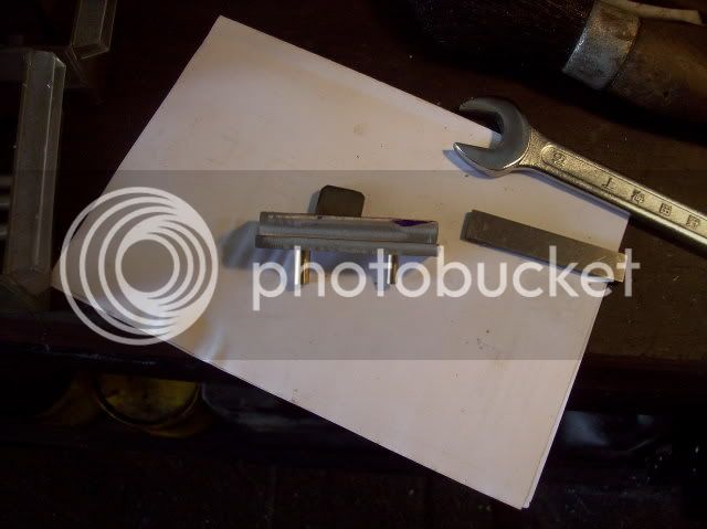
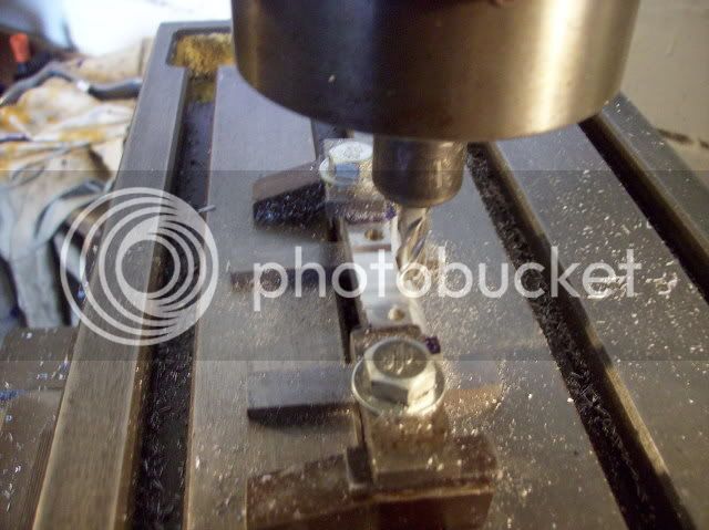
Back to the engine, I managed to get a little done today - completed the conrod jig and started to profile the rod.
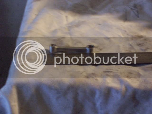
The rod blank, jig and its pins assembled.
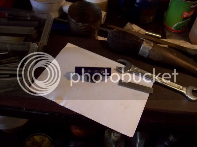
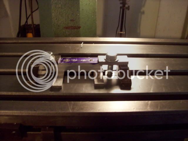
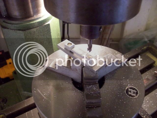
The set up for starting the profile. The jig pins are in the table slot and pressed against the back side of the slot. Hopefully this will give the correct angle for the rod side.
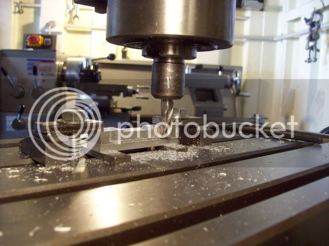
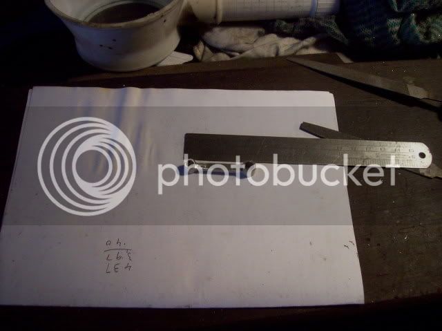
The conrod 1/4 complete.
That was all I had time for today as we had a meeting with our builder this arvo which went pretty well so things are pretty much back on an even keel.
Regards
Bob
: ::bow: :bow: :bow:Back to the engine, I managed to get a little done today - completed the conrod jig and started to profile the rod.
The rod blank, jig and its pins assembled.
The set up for starting the profile. The jig pins are in the table slot and pressed against the back side of the slot. Hopefully this will give the correct angle for the rod side.
The conrod 1/4 complete.
That was all I had time for today as we had a meeting with our builder this arvo which went pretty well so things are pretty much back on an even keel.
Regards
Bob
Maryak
Well-Known Member
- Joined
- Sep 12, 2008
- Messages
- 4,990
- Reaction score
- 77
Today saw the connecting rod completed, fiddly little sucker
I can't tell you how glad I am I made that little jig worked a treat both on the mill table and in the rotary table.
I am starting to wonder now if aluminium will handle the forces involved without bending. I guess we'll find out if the thing runs : :
Pins moved over and milling the other side of the rod.
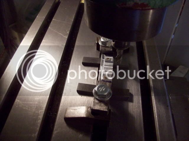
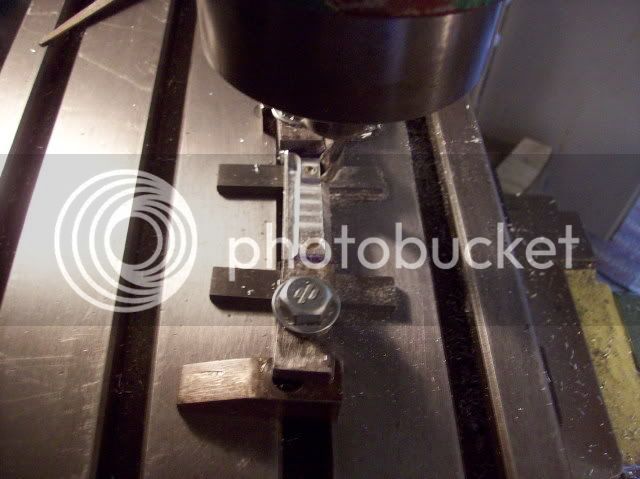
Milling the other side and overall height after turning over in the jig.
Profiling the ends using the rotary table.
The finished rod - sorry about the quality :
Have a good day
I can't tell you how glad I am I made that little jig
worked a treat both on the mill table and in the rotary table.I am starting to wonder now if aluminium will handle the forces involved without bending. I guess we'll find out if the thing runs :
:Pins moved over and milling the other side of the rod.
Milling the other side and overall height after turning over in the jig.
Profiling the ends using the rotary table.
The finished rod - sorry about the quality :
Have a good day


$39.99
$49.99
Sunnytech Low Temperature Stirling Engine Motor Steam Heat Education Model Toy Kit For mechanical skills (LT001)
stirlingtechonline


$99.99
AHS Outdoor Wood Boiler Yearly Maintenance Kit with Water Treatment - ProTech 300 & Test Kit
Alternative Heating & Supplies

$12.56
$39.95
Complete Plans for Building Horse Barns Big and Small(3rd Edition)
ThriftBooks-Atlanta


$519.19
$699.00
FoxAlien Masuter Pro CNC Router Machine, Upgraded 3-Axis Engraving All-Metal Milling Machine for Wood Acrylic MDF Nylon Carving Cutting
FoxAlien Official


$24.99
$34.99
Bowl Sander Tool Kit w/Dual Bearing Head & Hardwood Handle | 42PC Wood Sander Set | 2" Hook & Loop Sanding Disc Sandpaper Assortment | 1/4" Mandrel Bowl Sander for Woodturning | Wood Lathe Tools
Peachtree Woodworking Supply Inc

$89.99
Outdoor Wood Boiler Water Treatment Rust Inhibitor- AmTech 300 & Test Kit
Alternative Heating & Supplies


$94.99
$109.99
AHS Woodmaster 4400 Maintenance Kit for Outdoor Wood Boiler Treatment
Alternative Heating & Supplies


Maryak
Well-Known Member
- Joined
- Sep 12, 2008
- Messages
- 4,990
- Reaction score
- 77
yes bloody small
well done eh
your mounting must be very good all the small stuff like that i have either
given flying lessons too
or crushed, trying to stop the flying lessons
i'll try your way next time i do something small
thanks
and heck, well done
cheers Bob :bow: :bow: :bow:
jack
SERCEFLYER
Member
- Joined
- Oct 1, 2008
- Messages
- 24
- Reaction score
- 0
As long as the engine does not get flooded and suffer from "hydrolic lock", aluminum should be ok for the con rod.
Nice progress today! What's next? Head?
George
Nice progress today! What's next? Head?
George
Maryak
Well-Known Member
- Joined
- Sep 12, 2008
- Messages
- 4,990
- Reaction score
- 77
Thanks Jack, Kevin and George for your support and input :bow:
Next will be the gudgeon pin followed by the crankshaft. If that's all OK, will make a jig for drilling the holes in the crankcase, cylinder base and head. Then the head etc.
Jack, leave lumps on the ends, sides called chucking pieces so you can hang onto things, put them in the place where you can do most of the work before removing them. Then you've got some anti flying in place which wont damage the actual part this + patience and small cutting depths ;D
Best Regards
Bob
Philjoe5
Well-Known Member
- Joined
- Jul 12, 2007
- Messages
- 1,727
- Reaction score
- 321
Hi Bob,
I just picked up this thread and read the 9 pages with keen interest. First of all, glad to hear your Mrs. is not going through a serious medical issue. Thanks for your great documentation of this build particularly the details of making the lap. Being a newbie myself and quite ignorant of how this process is done correctly, I've made what I thought qualified as a lap but now I'm not so sure. I guess we can judge by the end result, which is a running engine, which I have in fact made. But honestly I don't think I've ever achieved a "mirror" finish in a bore. Is this a more important or necessary requirement for an engine of this type/size? I may try your technique on a Stirling engine I made but has never run properly. I know for a Stirling a "mirror" finish bore is likely a requirement for it to run.
Cheers,
Phil
Bob, glad to hear you and the Mrs. are in the clear! That's great news!
Your connecting rod came out well. Thought it is small, I think that it will be just fine for the purpose. It is small, but so is the volume of the engine. There shouldn't be enough push on the piston/rod assembly to hurt anything. I'm with you, it is small, but in perspective to the rest of the engine... Not so much.
Keep up the great work!
Maryak
Well-Known Member
- Joined
- Sep 12, 2008
- Messages
- 4,990
- Reaction score
- 77
Dear Philjoe5,
Thanks for your kind words
I'm a novice too when it comes to this lapping business, just read a couple of old books I had about the place. I would not call my cylinder or piston a "mirror finish" - Polished yes. In the good old days, things were finished off with white lead and tallow, enabling a mirror finish but white lead is not available any more and I'm sure long term lappers had a good dose of lead poisoning from their efforts.
I believe a good sliding fit to 0.0001" is required, (about the same level of accuracy as diesel engine injectors/fuel pumps, and again I would call the look of such parts polished but not mirror.
As I found out, the relative length of lap versus lappee is important, about 2-3 to one, i.e. a cylinder lap is longer than the cylinder and a piston lap is shorter than the piston. You can get really high tech and make fancy expanding laps and truing laps, (which are shorter than the lappee).
Hope this helps but as I said I'm a novice at this lapping game.
Regards
Bob :-\
Maryak
Well-Known Member
- Joined
- Sep 12, 2008
- Messages
- 4,990
- Reaction score
- 77
W/E,
Thanks again for your continued encouragement and concern for Galina, a CT scan next week should put the whole matter behind us. That's you and George who think the Al will be OK in the conrod, so I'll stick with it. :
Best Regards
Bob
Thanks again for your continued encouragement and concern for Galina, a CT scan next week should put the whole matter behind us. That's you and George who think the Al will be OK in the conrod, so I'll stick with it. :
Best Regards
Bob
Maryak
Well-Known Member
- Joined
- Sep 12, 2008
- Messages
- 4,990
- Reaction score
- 77
Achieved less than I was hoping for today, the gudgeon pin took much more time to lap and fit to the conrod than I anticipated. For some reason I had great difficulty in getting the lap to charge with abrasive and initially managed to transfer brass from the lap to the pin. Maybe a brass lap was not a good idea and I should have used cast iron or copper ??? ??? ??? Got the little sucker in the end ;D
A better picture of the finished connecting rod
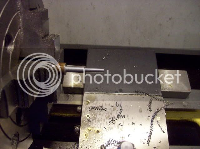
The pin and crankshaft laps.
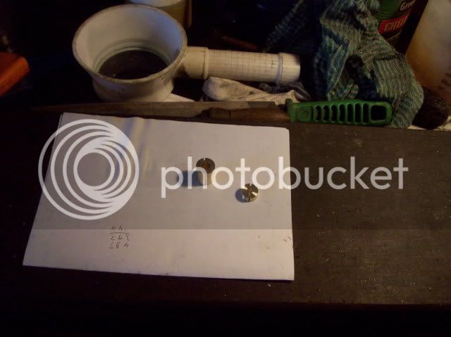
The finished gudgeon pin.
The gudgeon pin and dummy piston and conrod assembled.
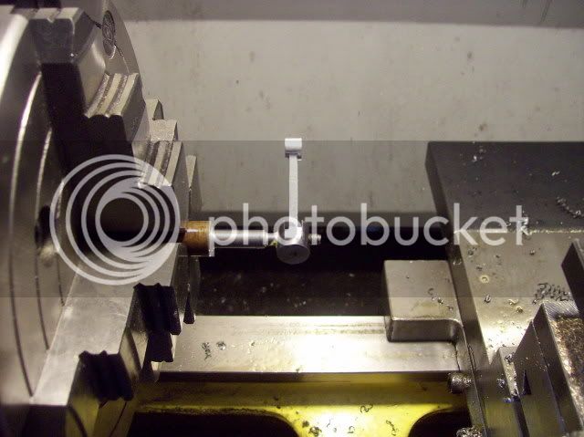
The piston and conrod ready for screwing and soldering.

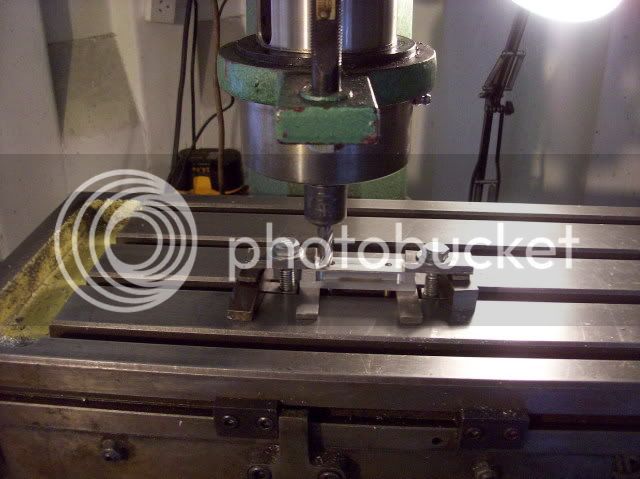
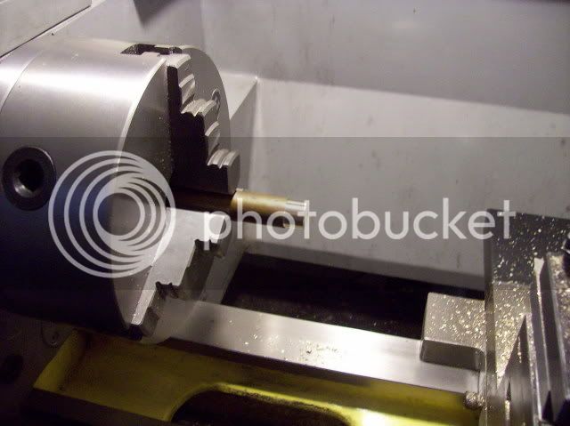
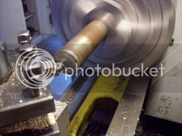
A lump for the crankshaft being faced.
And that was my lot for today as we had a meeting with our builder in the afternoon which went pretty well
A better picture of the finished connecting rod
The pin and crankshaft laps.
The finished gudgeon pin.
The gudgeon pin and dummy piston and conrod assembled.
The piston and conrod ready for screwing and soldering.
A lump for the crankshaft being faced.
And that was my lot for today as we had a meeting with our builder in the afternoon which went pretty well
Bob,
I've not posted a lot in here but I have been watching avidly, much better than Mrs CC's choice in TV .......... anyway, I'd just like to say thanks for your hard work in both machining and posting .............. and explaining ........... don't arf' elp us newb's
Thanks Bob .............. keep it coming ;D ............ please 8)
CC
I've not posted a lot in here but I have been watching avidly, much better than Mrs CC's choice in TV
.......... anyway, I'd just like to say thanks for your hard work in both machining and posting .............. and explaining ........... don't arf' elp us newb's Thanks Bob .............. keep it coming ;D ............ please 8)
CC
Maryak
Well-Known Member
- Joined
- Sep 12, 2008
- Messages
- 4,990
- Reaction score
- 77
CC and Kb,
Thanks for your support and encouragement. :bow:
I have derived a lot of pleasure myself from the discipline of documenting my progress and/or lack thereof.
Every post from other members has only added to my determination to keep it up. It's also given me warm fuzzies to be a part of a great bunch of people.
Thank you all. :bow: :bow: :bow:
Maryak said:It's also given me warm fuzzies to be a part of a great bunch of people.
Just watch out for the Fluffy Bunnies ;D
CC
Similar threads
- Replies
- 319
- Views
- 53K
- Replies
- 117
- Views
- 42K
- Replies
- 21
- Views
- 7K