1/4 scale V8, first project.

Home Model Engine Machinist Forum

Help Support Home Model Engine Machinist Forum:

This site may earn a commission from merchant affiliate links, including eBay, Amazon, and others.
Ha!, found it.

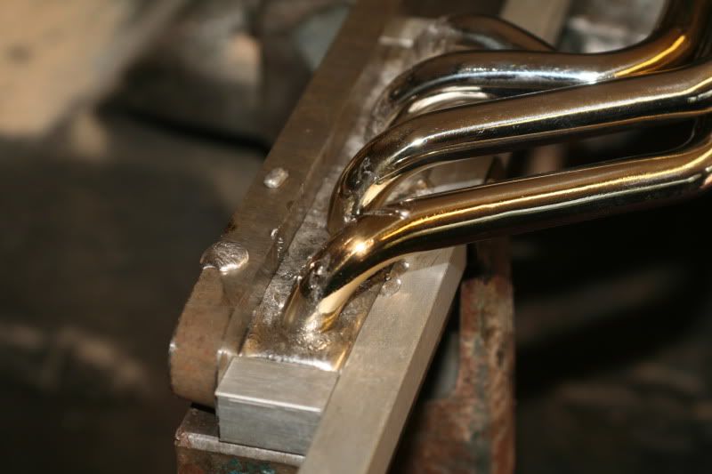
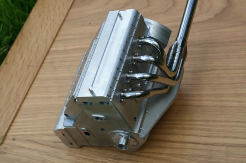
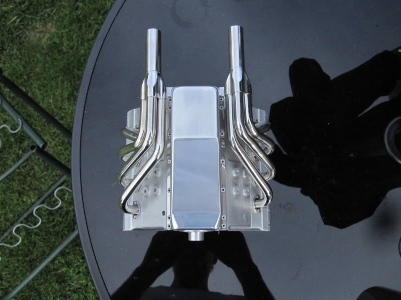
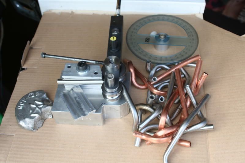
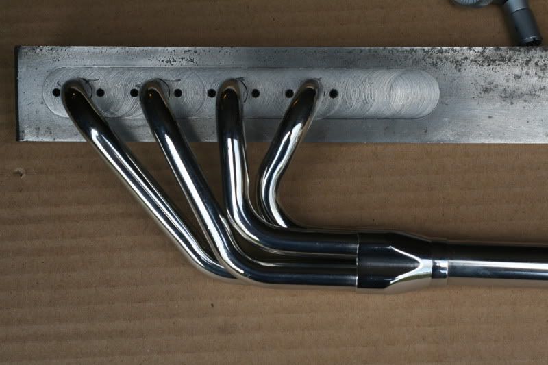
First pic shows the tube bender I've just finished.
I wanted to do the tightest bends possible in 10mm stainless. They ended up at 16mm inside radius on the bends.
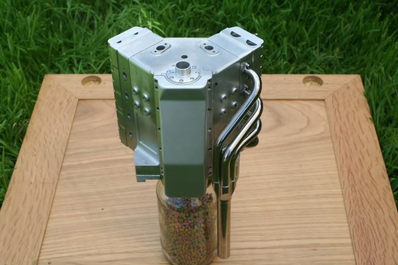
The tubes were filled with low melting point metal before being bent.
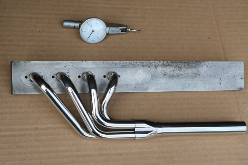
The bends are so tight that they still distorted slightly but most of the defects filed out.

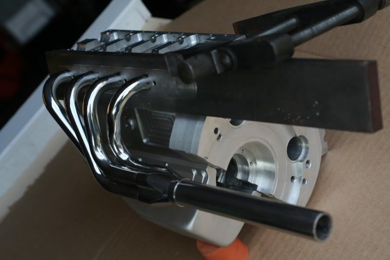
The pile of bends is all the trials it took before pulling the proper bends. I started with copper pipe,to get the angles, then unfilled stainless to work out the distance between the turns, then pulled the filled tubes.
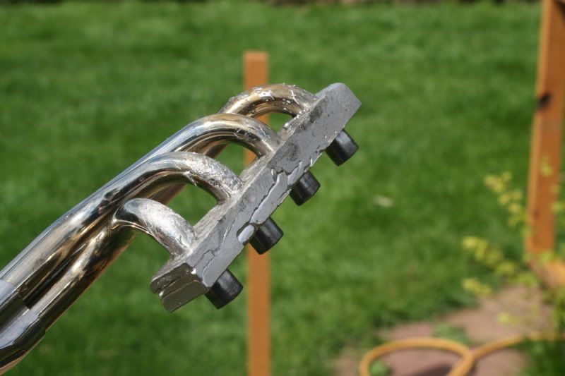
I polished them just for the hell of it, I know they'll go blue, etc. when (if) the engine fires up.

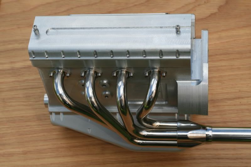
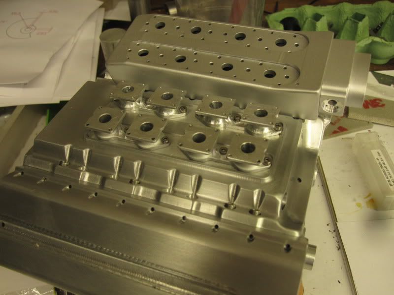
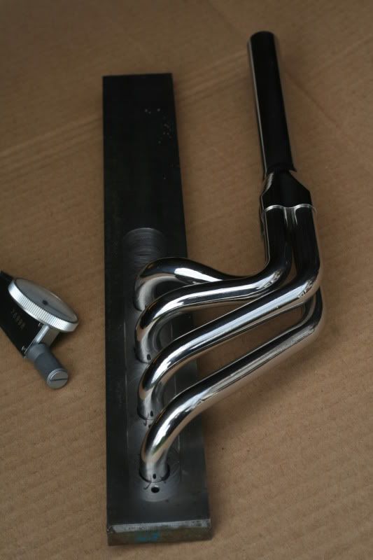
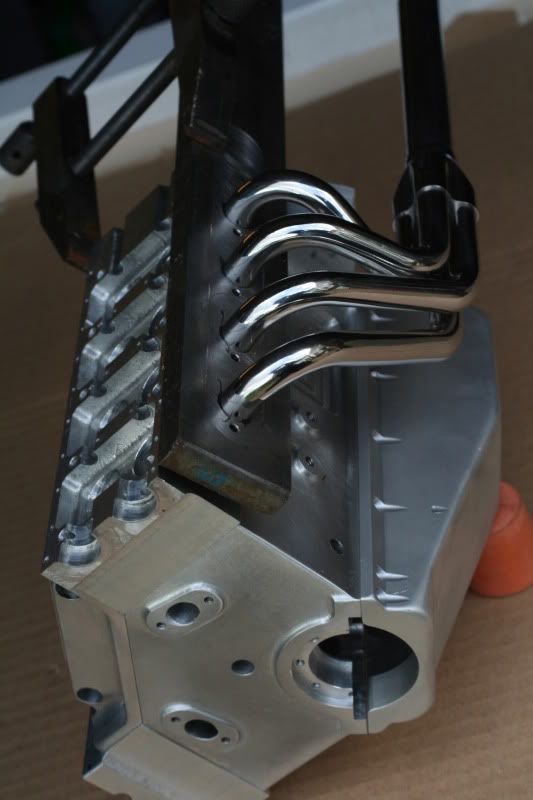
The 10mm jig plate was a great help as the pipes could be pushed in and tweaked slightly to get all 4 to line up with the collector.

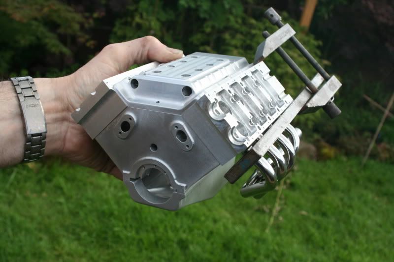
Just got to make a mirror image set now for the other side!!

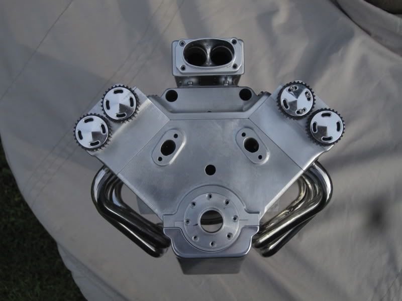
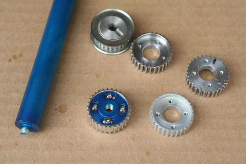
The vernier cam pulley was just another trial to see if they will look believable on the engine, although they do actually work. Not sure if the blue looks tacky or not. Maybe try some with a lighter depth of blue, (not so long in the dye after anodising). Wished I'd tried anodising years ago.
001-1.jpg

005.jpg


006.jpg


009-1.jpg


012-1.jpg


014.jpg


016.jpg


018.jpg


That is just WOW
:bow: :bow:
Pete
 
Keith-

This whole thing is mindblowing! The header is unreal. I am also impressed with the anodizing. Any chance of a how to?

Karma away.

Bob
 
I've been lurking for months now and your project has flushed me out of the woods, I'm speechless ... almost. Your headers are a work of art, as is the rest of your engine. Keep those pictures coming. Thanks for the inspiration and for sharing. Simon
 
Steve, they are just pressed into the collector at the moment, I'm not sure how to fix them. I was actually going to wait until you'd done yours first, and take it from there.
My mate reckons he knows someone who can tig weld hypodermic tubes together, so I'm going to follow that one up too.
This will be one job I won't mind farming out, if the claims of being able to lay perfect 20 thou' fillet welds are true.

Bob, I would be happy to do a how-to on anodising, but I need to play with it a bit more first. Have just got some red dye so I'm going to do a bit today.
Keith.
 
Your headers are outstanding. To get the double bend and still have them in the right place is extremely hard. This is going to be a beautiful piece of engineering. I watch each day for the next installment.
gbritnell
 
Wonderful job, especially on the collector. :bow:
If you weld them, you will need both the flange and collector ends secured against warping, then tacked. Preheating will definately help, and a good plan to quickly work opposite sides of the joints to minimize distortion.
 
Well it looks at the moment that tig welding the exhaust flanges may be more of a problem than I thought.

However I wanted to see what the manifold looked like on the block, before I made the 2nd manifold.
I decided to make the individual flanges and then countersink the rear faces. The pipes could be pushed through, flushed off and then flared out into the countersink. Bolting the flanges to the heads should keep the pipes rigid, especially if I left the end of the pipes a couple of thou' proud of the flanges.

The hardest bit would be flaring the pipe over without it pushing back through the flange.
I decided to mock everything up and then cast it all in place with low melting point metal.

I have no pics of the flaring operation as I'm not used to documenting my work and keep forgetting to pick the camera up.
I've also roughed out a couple of cam covers.

The exhaust flanges look slightly out of proportion (too large) but as it took 8 hours solid to make 8 of them, I'm going to stick with them.
002.jpg


005-1.jpg


011.jpg


015.jpg


022.jpg


th_confused0052

amazing work - nothing else to add, just amazing
 
Time for a quick update.
Not got too much more done. I wasted a lot of time on an induction system, which sounded good in theory but it didn't look very nice, so it was scrapped.
I then went for a plenum type system, with a twin throttle body. It still doesn't look how I imagined, but it's not too bad so it'll do for now.
I'm playing with different surface finishes all the time, so this has different textures on various parts. I think I'll try shot peening the cam covers next, and anodise them black, with a centre polished cover for the plug grommets.

I ought to get onwith the internals really, but I want to make sure it's going to look the part first.

By the way, getting the second set of headers to fit right and be a mirror image of the first set was a nightmare.
Went through 18 feet of tube to get both sets right!

016-1.jpg


019.jpg


018-1.jpg


014-1.jpg


009-2.jpg


006-1.jpg


015-1.jpg


Any chance you could show us how you created the parts for your beautiful exhaust system?
 
That is just Stunning :bow: :bow:
really really exceptional
nice and big too by the look of her!!
Pete
 
:bow: :bow: :bow:
That is a fantastic looking engine.
Brock
 
Looks really good. I personally want to see the valve actuation.
 
Thanks all.
George, I don't appear to have any more pics of doing the exhaust than what's already been posted.
I know at the start I wanted the tightest bends possible from 10mm tube, and I made the bender to suit.
One essential part is the protractor for measuring the angle of the pull.
Next essential was to clamp the tube tight between the rollers before pulling. This was done by having the wheel on the handle on an eccentric axle, so all the clearance could be taken out.

The handle wheel runs on ball races, which reduced the stretching of the tubes slightly.

The thick jig plate was invaluable for holding the tubes rigidly in place for alignment and for the final bits of tweaking/bending.

Lastly, the tubes needed to be filled with low melting point metal before bending. I tried some bends without this but they were awful.

Having done all this the outer radii of the bent tubes were still a bit knobbly, and each tube had to be filed round again after bending, which was the most time consuming part really.

Inevitably, the tighter the radius, the harder it is to get to look right, so the question for anyone wanting to do something similar is, how tight do you want to go?

Looking at my finished exhaust it would look better if the bends were even tighter, it still looks a bit clumsy in real life, but I think if I went much tighter than I've got, then the outer radius would be starting to split open with the stretching.

Lakc, I've drawn up the valve gear but I'm not 100% happy with it. The only doubt I've got is if oil managed to get under the bucket tappets and form a hydraulic lock on startup, as there's nowhere for it to drain away at present.
I'll try and get a pic posted, although the only way I can think to do it, in my non-computerized brain, is to print it off the cad and photograph it.

Cheers
 

Latest posts

Back
Top