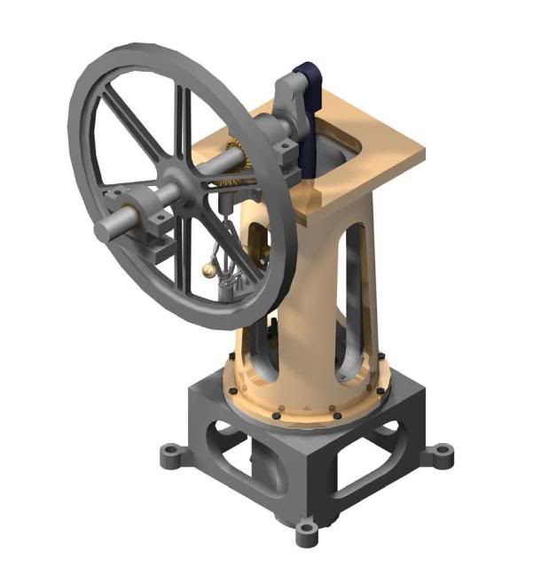
William Fairbairn 10 hp.

Home Model Engine Machinist Forum

Help Support Home Model Engine Machinist Forum:

This site may earn a commission from merchant affiliate links, including eBay, Amazon, and others.
The rotational acceleration (centrifugal acceleration) is ( R omega squared.)


Omega ( W) should be in radians /second.

2 Pi N = 2 x 3.14159 X 100/60 = 10.47 rad/second for 100 rpm

R you have stated as 0.0578 m

Therefore

.0578 x (10.47) squared = 6.33 meters / second squared

1 g is 9.81 meters / second squared......so

6.33/9.81 = 0.645 g's from centrifugal force...don't forget that gravity is pulling down with 1 g...

Ya need more speed....or bigger balls Bob ;D (Sorry it was too easy)

Because of the speed factor, I would speed the governer up


Dave

 
Puzzled? I can follow the math but I don't understand the result. What does .645g mean? Where is it measured and in what direction? How did you come to the value of R? How does friction matter? If the gov is stable (not hunting) the linkage is not moving at the pivot points so there is no friction. It would seem to me that any friction at the pivots would only have a damping effect on the mechanism anyway. Any rotational friction would just add to the overall friction of the whole engine and not matter in the gov calculation.

I have not built a governor yet but plan to soon. The question that concerns me is how much force is required to move the throttle and over what distance. Without that info, how can you design a working gov?

A nice drawing with force vectors would be a great help. Can you point me to a source?

Jerry
 
The calculation above just gives the horizontal acceleration as a fraction of gravity. F=MA will give the force (plugging in the mass of the balls). Then you need the geometry of the regulator to determine the force applied to the relief valve.
 
Gerry,

"A nice drawing with force vectors would be a great help. Can you point me to a source?"


Yes it would be...but not at 6 in the morning.....maybe later this afternoon


"The calculation above just gives the horizontal acceleration as a fraction of gravity. F=MA will give the force (plugging in the mass of the balls). Then you need the geometry of the regulator to determine the force applied to the relief valve."

I used the units of g's as I can now multiply the weight by 0.64 and get the centripedal force directly....I cheated....and of course...mother earth is pulling down so to speak so a force vector will be required...but I don't know the geometry....unless Bob would like to share? ::)


Dave

 
steamer said:
...but I don't know the geometry....unless Bob would like to share? ::)
Dave

Thanks for the input guys :bow: :bow: :bow:

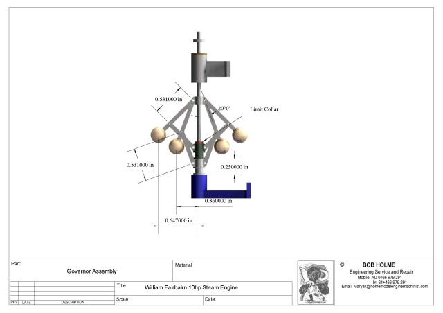
Below is the geometry. The travel is limited as much more and the balls would hit the column/flywheel :eek:

As yet I have not designed the levers which will operate a choke in the steam line. ::)

WFB10Governor-2.jpg


Best Regards
Bob
 
The drawing doesn't show the travel length, so I assume it's .25". With no motion, the separation of the ends of the links (20 degree equilateral triangle) is .998". With the bottom link raised .25" the end links are separated by .748 and form a 45.2 degree angle. This is close enough to 45 so that the horizontal and vertical vectors are the same, meaning the collar sees the same force as the balls, minus friction effects.
 
Bob

A new member recently posted a thread about building a 1/4 HP Verticle Steam engine from plans found in a book from 1904 by Paul N Hasluck. The book is free from Google Books and is worth taking a look.

http://books.google.com/books?id=UU...onepage&q=Paul N. Hasluck metalworking&f=true

The book includes a number of projects. The vertical engine mentioned as well as a horizontal of similar size. Booth engines include detailed drawing of their governors and throttle valve linkage. On page 620 there is a very good section on setting and adjusting the governor to achieve the desired speed.

The two governors described are very different, one with a vertical shaft and one with a horizontal shaft and the geometry of the arms is very different but the weight balls are 1" diameter and the target speed is in the range of 100 - 200 RPM.

Jerry
 
Gerry,

Thanks for the link. I am unable to browse the book because I am not resident in USA. Google book partners and various statutes preclude foreigners from freebies.

Best Regards
Bob
 
Hi Bob. Pity about the free book thing. Just wondering if anyone in the US could email the book to people outside the US. If not I would be happy to pay for someone to put it on a disc and send it to Oz
 
looking real good Bob
maybe I need one for my shelf :bow:
 
Looks good Bob!...I assume the governer has the butterfly valve for throttling..

I'm getting real interersted in what's holding that outboard crank bearing..... ;D

Dave
 
Hi Bob. That outboard bearing has got me stumped too. Engine is looking great :bow:
 
steamer said:
Looks good Bob!...I assume the governer has the butterfly valve for throttling..

I'm getting real interersted in what's holding that outboard crank bearing..... ;D

Dave

Yes some sort of plate not quite sure which.

Herbiev said:
Hi Bob. That outboard bearing has got me stumped too. Engine is looking great :bow:

Currently one could call it a floating bearing ;D It's floating about waiting for inspiration to remove the air from its' base and allow it to settle gently onto SOMETHING substantial.

Best Regards
Bob

 
Back
Top