What chuck size for rotary table?

Home Model Engine Machinist Forum

Help Support Home Model Engine Machinist Forum:

This site may earn a commission from merchant affiliate links, including eBay, Amazon, and others.
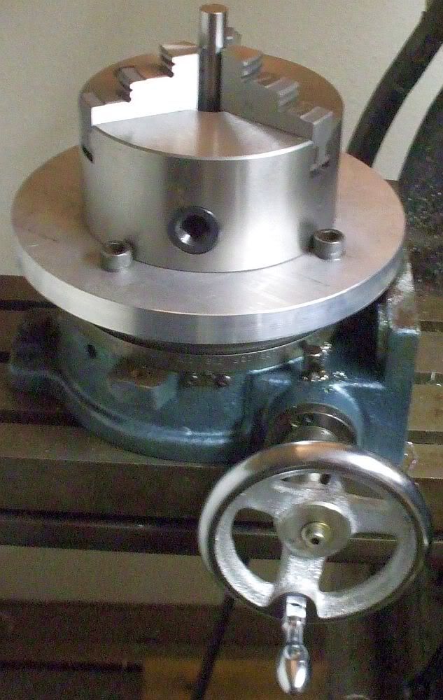
Hurray!!! Its finished. I was able to avoid the horrible 4 jaw chuck centering requirement---I put the other set of jaws in my 3 jaw chuck and was able to get a good grip on the 3.740 dia. "registered" area, to hold everything while I put the counterbore in for the MT2 tapered stub. It all fits and works like I had anticipated. Now all I have to do is figure out something to build using the rotary table/chuck combination.--Probably a flywheel with spokes for another steam engine.---Brian--(and if you are wondering about the offset hole in the end of the MT2 stub---that peice of steel was cut from something that in a previous life was used when making the eccentric on my "rocking beam" steam engine.)
__________________
Brian


FINISHED ADAPTER PLATE--CHUCK TO ROTARY TABLE003.JPG
 
Well, everything is done. I made up 3 steel T-nuts and assembled everything. It looks good, and if the contract I've been waiting for ever materializes, I'll probably take some of the money from it and buy a "dedicated" 3 jaw chuck for the rotary table.
 
Brian: I am not sure if I can give you any better advice than has already been given but I will add my $.02.
I bought a X/Y 8" rotary table before I had a mill/drill. When I got the mill/drill I removed the X/Y base and made a dovetail seat that bolted to a homemade angle plate (heavy, but it works) that I can mount horizontal or vertical. My rotary table does not have a center taper hole so I machined a "lathe spindle" adapter and bolted it into the center of the RT. Now it is possible to machine a part on the lathe, put the chuck with the part on the RT, do my milling, and put it back on the lathe for more machining if necessary.
This has been very handy at times. If the RT is centered under the mill spindle the part in the chuck will be centered on the RT and to the mill spindle when the chuck is mounted on the RT. I have a Craftsman/Atlas 12' lathe with a threaded spindle and 2- 8"dia 4 jaw chucks that make it nice to break into a job and do something else if needed without losing the setup.
I also bought a 3"dia.-- 4 jaw chuck so the spindle of the mill will clear the chuck on small parts when using short end mills.
I do like your design as it looks to be quite rigid while mine leaves something to be desired in that regard.
Very rarely does the 3 jaw chuck get used here, as John brought up, it is somehow relaxing to see how "centered" I can get the stock before starting cutting. I use a 1" dial indicator to "dial" in the stock and once you get familiar with the operation it gets easier.
Good luck-----don
 
Here is some more free advice (you know the value of free advice).

Make a second chuck key for your four jaw so that you can use one on each side to bring your workpiece to the desired point on your indicator (1/2 of the error between the two). Do the same thing on the other pair of jaws and then repeat. Three or four repetitions should have you with almost no movement on the indicator.

When working on a disc, you have to be sure that the workpiece is sitting square in the chuck, either tight against the jaws, against the chuck face or against parallels between the piece and the chuck face.

Always do the difficult operations first if possible. In this case, I would have made the MT2 taper first, mounted the plate to the taper and then put the taper in the headstock to cut the register. By taking a truing cut on both faces and the circumference everything will be as true as your lathe spindle is capable of.
 
Once upon a time, I hated my 4-jaw, I hated tramming the mill or vise, and generally any operation like that. These operations were frustrating, took ridiculous amounts of time, and it seemed like I was chasing my tail. Measure, tap, tap, measure (close!), tap, tap, measure (?!??!!! it's worse than it was, what gives!!!!).

The biggest problem I had was in not doing this kind of thing often enough. Eventually, I took some advice I saw elsewhere, and put away every lathe chuck except my 4-jaw. I had a rule that any time I went down to the shop the first thing I would do is intentionally take the mill head and vise out of tram and then tram them in. Every single time I went to the shop I went through this agony.

Oh how I hated it for about 2 weeks. And then one day I walked down to the shop and was so busy thinking about the project I was working on that I got the mill and vise trammed and a workpiece all lined up in the 4-jaw within about 20 minutes before realizing what I had done. Hallelujah! Somehow my hands had learned what my head was still wondering about.

There were little things along the way that helped out as well. For example, I took the time to measure how far a turn of the chuck key on my 4-jaw moves the workpiece: 0.060". Then it was easier to estimate what fraction of a turn was needed. I learned some more systematic ways to approach all of these operations.

But most of all, I just flat out did these operations a bunch of times in a row until it sank in. It's a lot nicer when you love your 4-jaw rather than fearing it, LOL.

Once I got to that stage, I knew that if I had to choose only 1 chuck, it would be a 4-jaw. And so that's the extra chuck that lives with my rotary table. And while a Morse Taper center and adapter would be nice, I never bothered because it just wasn't hard to center it by the time I got around to having a use for it.

That was one of the best 2 weeks I ever spent on this business, although I didn't build anything of particular note during that time.

Cheers,

BW
 
I've put this up before but perhaps it's worth repeating. This is something I wrote for the members of our club...

Centering Work in the Four Jaw Chuck

Probably every machinist has his own pet way of doing it. My technique works
for me. Take whatever is useful and modify as you see fit.

To easily center work in the 4J, you'll need to make yourself two tools.
First, make a dedicated holder of some sort so you can mount a dial indicator
(DI) on the tool post (or directly to the compound) with its axis
perpendicular to the spindle axis. Adjust the DI so its plunger is vertically
aligned with the spindle axis. An easy way to do this is to put a pointed tip
on the DI plunger and align the point to a dead center in the headstock. The
idea is to make something that you can drop into place, already aligned, and
lock down in ten seconds or so. Leave the DI permanently mounted to this
holder. A cheap import DI (<$15) is fine since we'll be using this only for
comparative, not absolute, measurement.

While you could use a conventional adjustable magnetic DI holder, I strongly
recommend that you make a dedicated mount that is easily installed and removed.
A general maxim of machining is that you'll be much more likely to do something
'the right way' if setting up to do it is quick and simple. If it isn't you're
much more likely to try some half-a$$ed setup that doesn't work and ends up
damaging the tool, the work, or, worst of all, you.

The second tool to make is a clone of your 4J chuck wrench. We're going to be
adjusting two jaws at a time and it's infinitely easier to do if you can move
both jaws in and out in concert without having to swap the wrench from hole to
hole. It's another example of the maxim I mentioned above. The clone wrench
doesn't have to be anything fancy. Machine a square tenon to match the
existing wrench on the end of some suitable stock, and drill for a press-fit
cross bar. Use your existing wrench as a guide for dimensions. I've found
that, if there's not a lot of room on the back side of the lathe, making the
clone somewhat shorter than the supplied wrench is a good idea.

Ok, now for the procedure. Mount the work in the 4J and roughly center -
either by eye or by using the concentric circles scribed into the face of most
4Js. Snug the jaws down so the work is held securely. Turn the chuck so one
jaw is at the nine o'clock position as seen looking from the tailstock down
the spindle axis. Use the cross-slide to bring the DI up against the work and
reading about the middle of its range (e.g., about 0.5" on a 1" DI). Turn the
scale on the DI so its needle indicates zero. Now swing the chuck through 180
degrees. Unless you've got an impossibly good eye, the DI will now read
something other than zero. (For an example, let's say it reads 0.038.) Turn
the DI scale so the zero is halfway to this reading. (Move the scale so the
needle points to 0.019.)

Now, insert both chuck wrenches and adjust the jaws so the DI needle points to
zero. Swing the chuck 180 degrees and check the reading - it should be close
to zero.

[Aside: If the part you're centering has the same dimension in both jaw axes
(i.e., it's not rectangular), the DI zero you established above will also be
the zero for adjusting the other two jaws below - another advantage of this
technique.]

Repeat this entire process for the two other jaws. [What we're doing here is
treating the 4J as two two-jaw chucks. We can do this because the jaw pairs
are orthogonal and, to first order, adjustments of one pair will have very
little effect on the setting of the other pair.]

If you've been careful, the total runout on the part should now be only a few
thou. Depending on your esthetics and the part requirements, this may be good
enough. If not, repeat the entire process until the runout meets your needs.
After centering, check to ensure that all the jaws are clamped down tightly.
It's easy to leave one loose. If you have (left one loose), you may need to
rerun the centering procedure after you've tightened it.

With this procedure, you should be able to center something to +/-0.001" in
ten minutes on your first try. With not much practice, you can get that
number down to one or two minutes. Soon your three-jaw will be gathering
dust.

One of the most common uses of the 4J is for drilling/boring offset holes in
eccentrics (i.e. cam drivers for model engines). In this case, you aren't
centering the stock itself (as we were above) but rather need to center the
location of the hole.

First centerdrill the location of the hole in the milling machine. Mount the
stock in the 4J and roughly center this centerdrilled hole. [A fast way to do
this is to use the pointy end of an edge finder held in the tailstock drill
chuck.] Now you need a PUMP CENTER. This is a longish rod (mine is ~10"
long). At the tailstock end is a spring-loaded female center. At the
headstock end is a rigid male center. The male center goes in your
centerdrilled hole. The female center is supported by a dead center in the
tailstock and the tailstock is adjusted to lightly compress the spring. The
DI is made to bear on the rod near the male center. Using the procedure
outlined above, adjust the jaws until the DI shows little or no runout.
Voila, the location of the offset hole is now centered.
 
Here's a method I learned from Jack Burns over on the HSM board that is amazingly simple and fast (he says it is the world's fastest way to center a 4-jaw):

1. After rough aligning to the chuck rings, using a dial indicator on the work-piece, rotate the spindle through one complete revolution noting the highest and lowest indicator readings;

2. Continue rotating the spindle and halt at exactly Midway between the above two readings, then zero the indicator bezel to the needle;

3. Rotate the spindle to bring jaw #1 ‘on plunger’ and adjust jaws #1 and #3 to re-zero the indicator; finally

4. Rotate the spindle 90 degrees and adjust jaws #2 and #4 to zero the indicator once again.

This is one of those things where I read it, it made total sense, it was elegant, and it made me feel stupid for not having thought of it myself. it works great and is really fast. Try it yourself.

Cheers,

BW

 
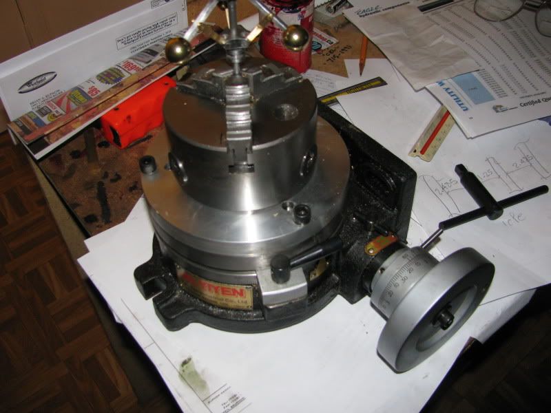
Yuasa6inrotarytablewith5inchuck.jpg


I used the assembly drawing in this thread that Brian Rupnow posted, except that:

1) the chuck had 3 back plate metric cap screws on 2.125" radius.
2) The plate to table screws were 3/8-16.
3) I made a continuation of the #2 Morse taper in the table all the way through the 5/8" plate with 1.25 degrees taper.
4) The clearance holes for and countersinks in the plate are over sized or milled slots so that the table-plate-chuck can be dialed in.

I am grateful for this thread.
 
This is an old thread that someone has revived. I actually bit the bullet a couple of months ago during my "Gear making adventure" and purchased a 4" diameter 3 jaw chuck and mounted it to my rotary table with a home made adapter. I am amazed at what it lets me do now in terms of "set-up" that I wouldn't even have thought of before.
3-jaw002.jpg
 

Latest posts

Back
Top