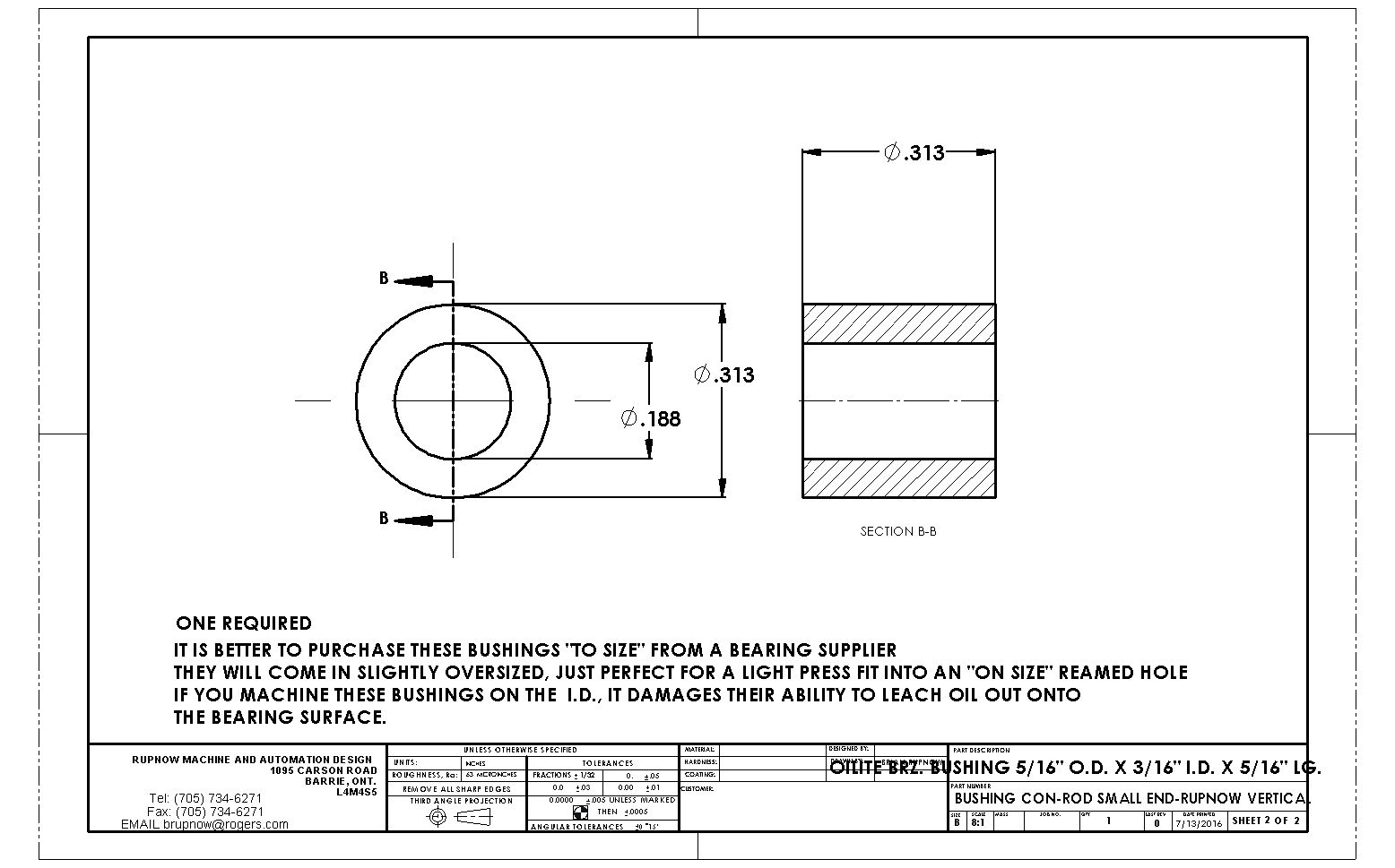
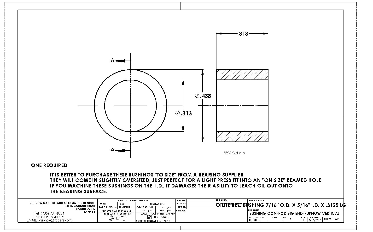
Thanks for the information Brian. I think I'll buy them from Travers. On the US site they are only $42 each. Still I'll buy the two I need for this project and then augment later as needed. I really want to cut the gears myself vs buying.
You are using an out of date browser. It may not display this or other websites correctly.
You should upgrade or use an alternative browser.
You should upgrade or use an alternative browser.
Vertical I.C. Rupnow Engine
- Thread starter Brian Rupnow
- Start date

Help Support Home Model Engine Machinist Forum:
This site may earn a commission from merchant affiliate
links, including eBay, Amazon, and others.
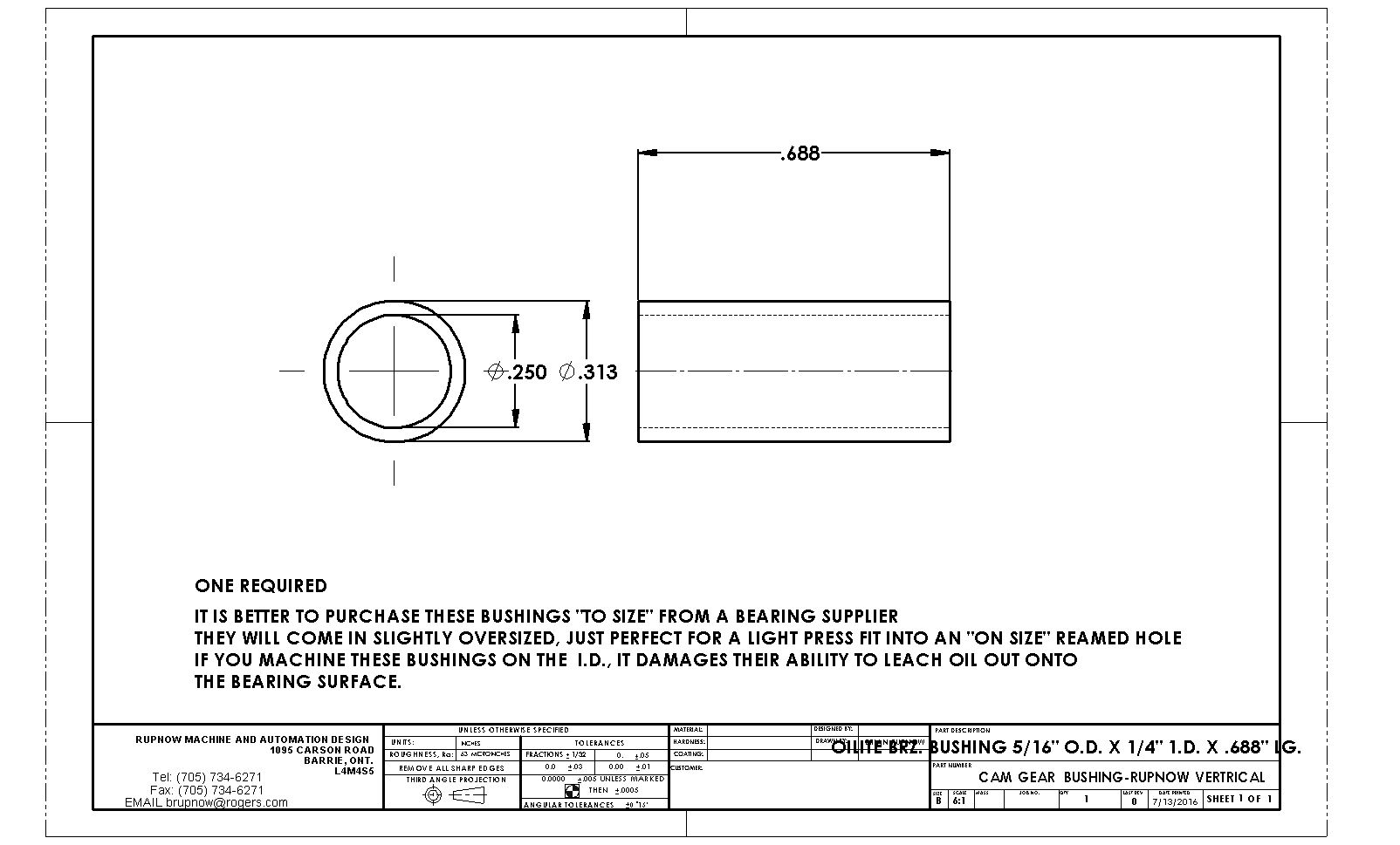
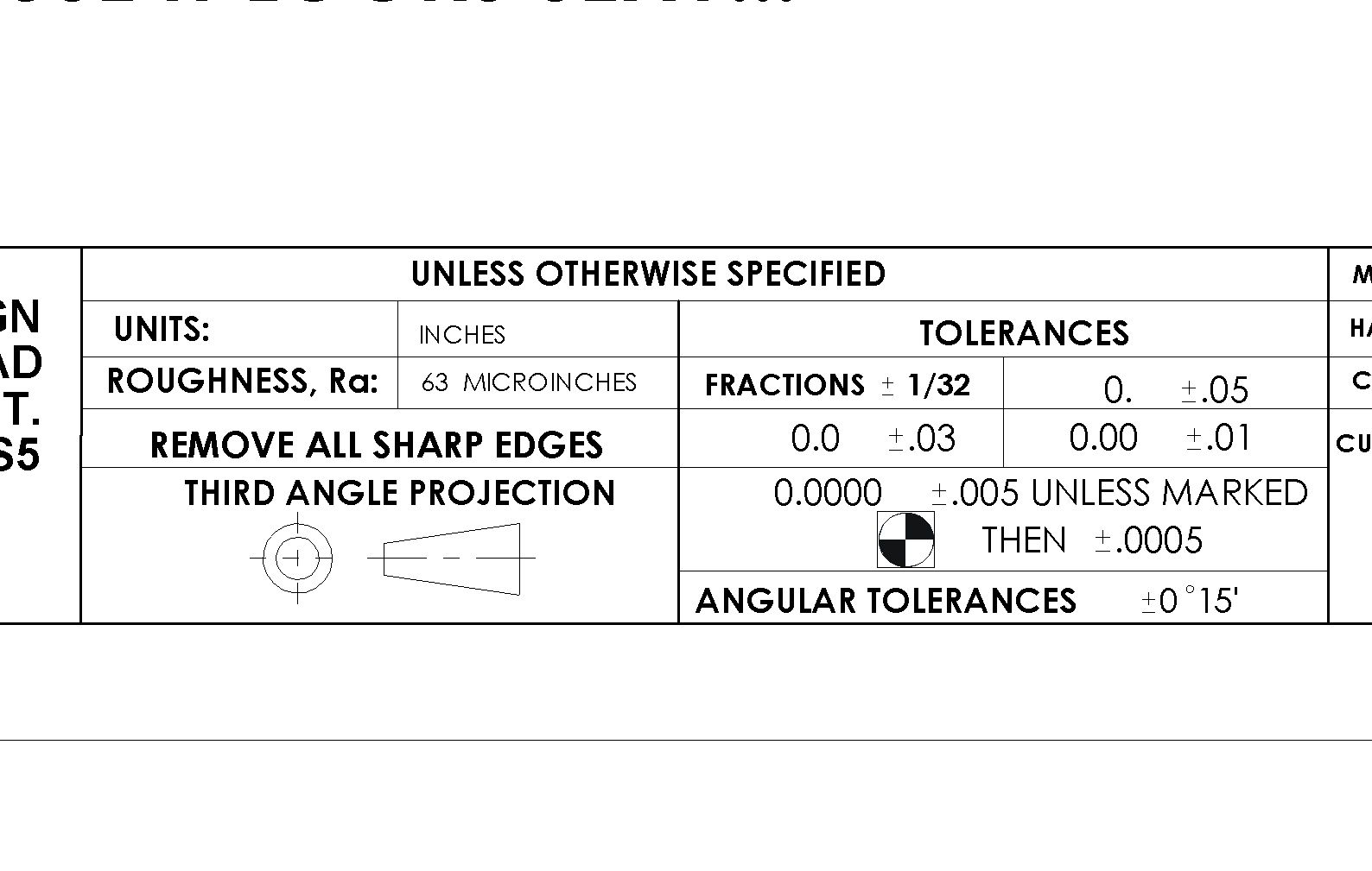
First time ever--somebody asked me about machining tolerances on my drawings. I don't think I have looked at these since I made up this drawing sheet 15 years ago, but here they are. When I machine engines, anything that is a sliding or rotating fit I try to make "dead nuts". Anything that is on the outside of the body and doesn't connect with any other part is +/- 1/32"---Brian

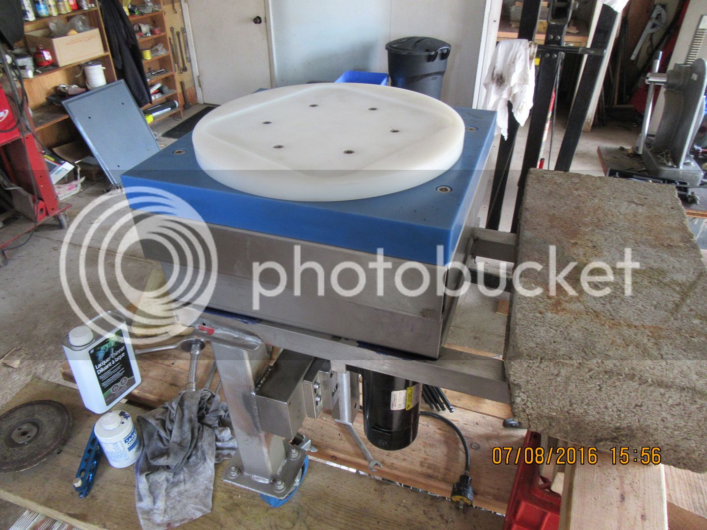
Well, Hurray for me!!! I just finished a powered rotary table for my bakery customer and it worked like a charm. I haven't been able to try it out because the gearmotor is a d.c. unit, and I had no way to power it. I finished it at 12:00 today, called my customer, and he drove up from Oakville and brought the motor controller with him. I told him--"Get ready with that controller, I'm going to plug it in, and if this thing squeals, smokes, or levitates, for Gods sake turn it off!!!" I plugged it in, and it turns smooth as silk, and very quietly. Oh happy Me!!! Now I can get back to important stuff like my vertical engine!!

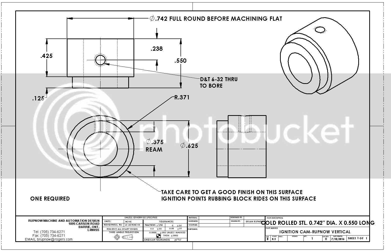
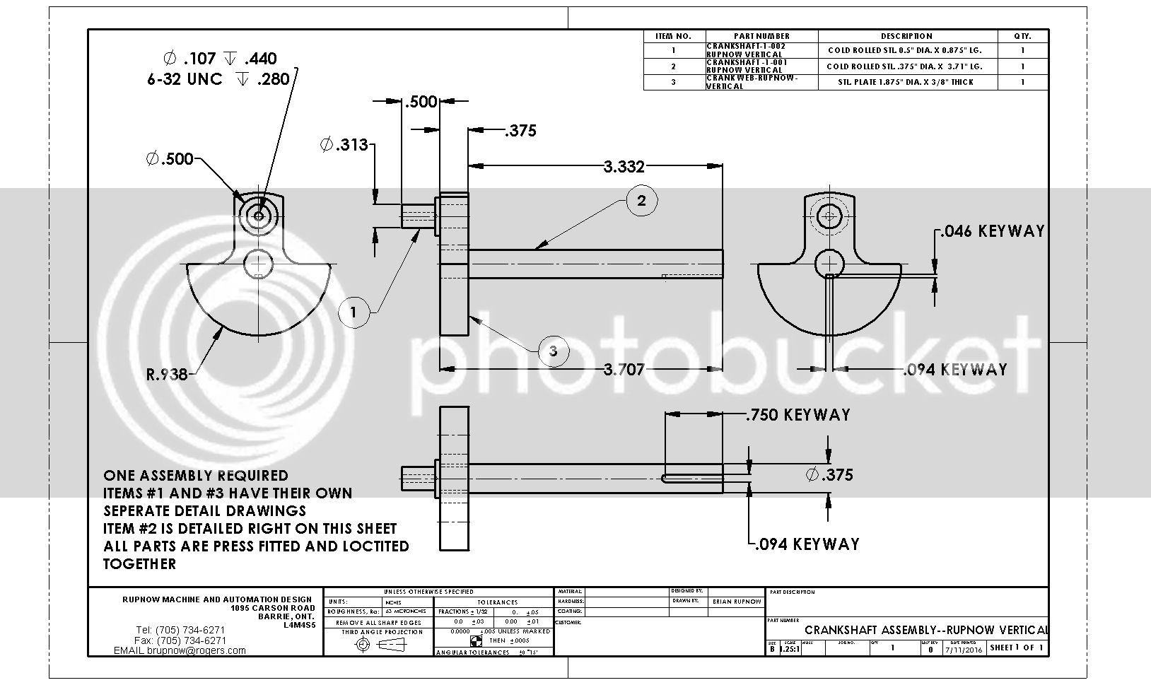
To keep things simple, I have decided to go with my old "tried and true" Chrysler ignition points. We will save the push-rod activated points for another engine. The points are from a 1970's era Chrysler product, and their number is 018-4126-8 A110P. The condenser which goes with them is part number 018-1555-4 G120P. To use these points, we have to move the flywheel out about 1/2" from it's original position, and this isn't a bad thing---Because---We can then extend the blue top plate out another 1/2" and make a perfect spot to mount a cooling fan, driven by a friction roller which rubs against the flywheel.
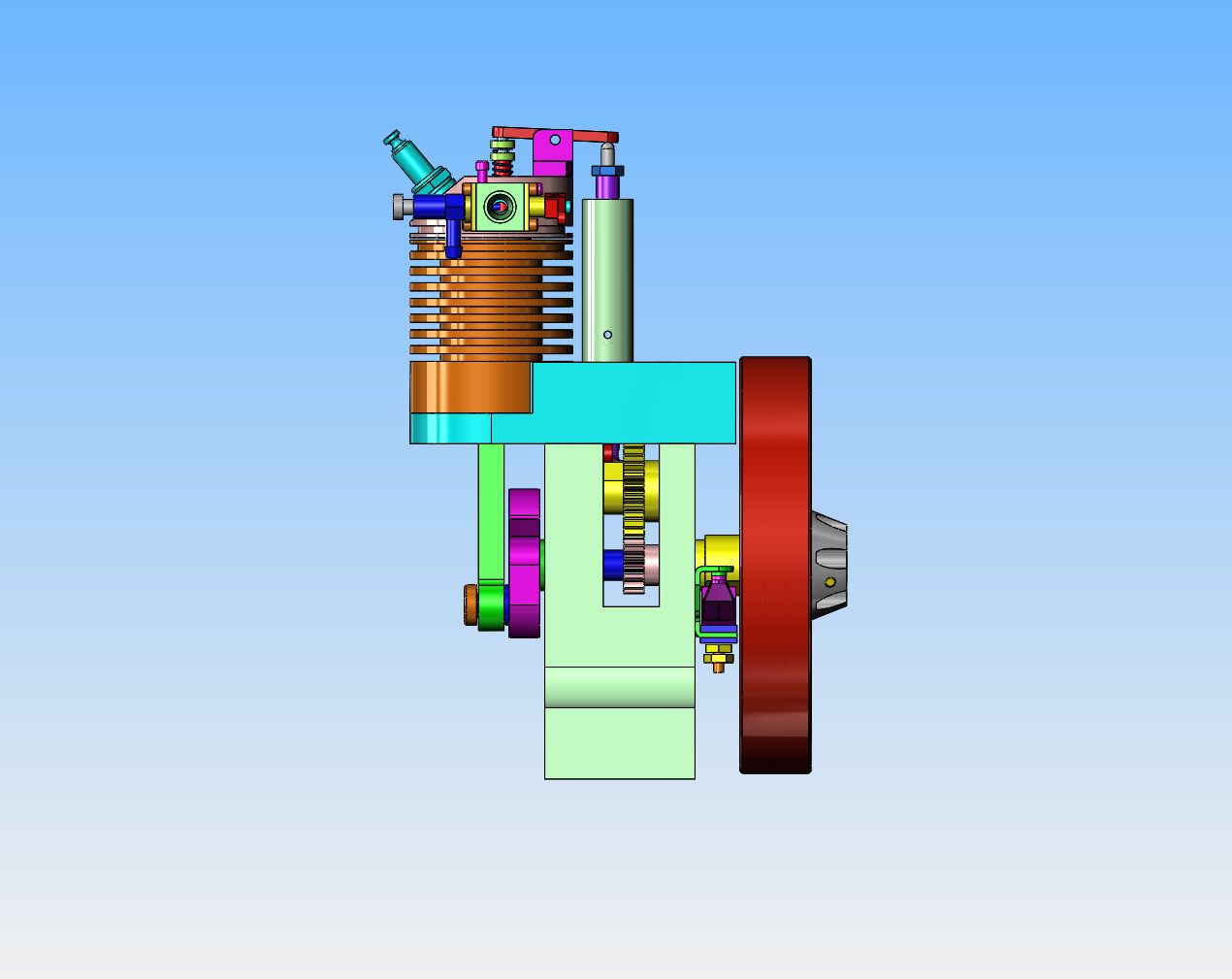
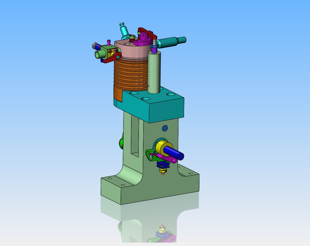
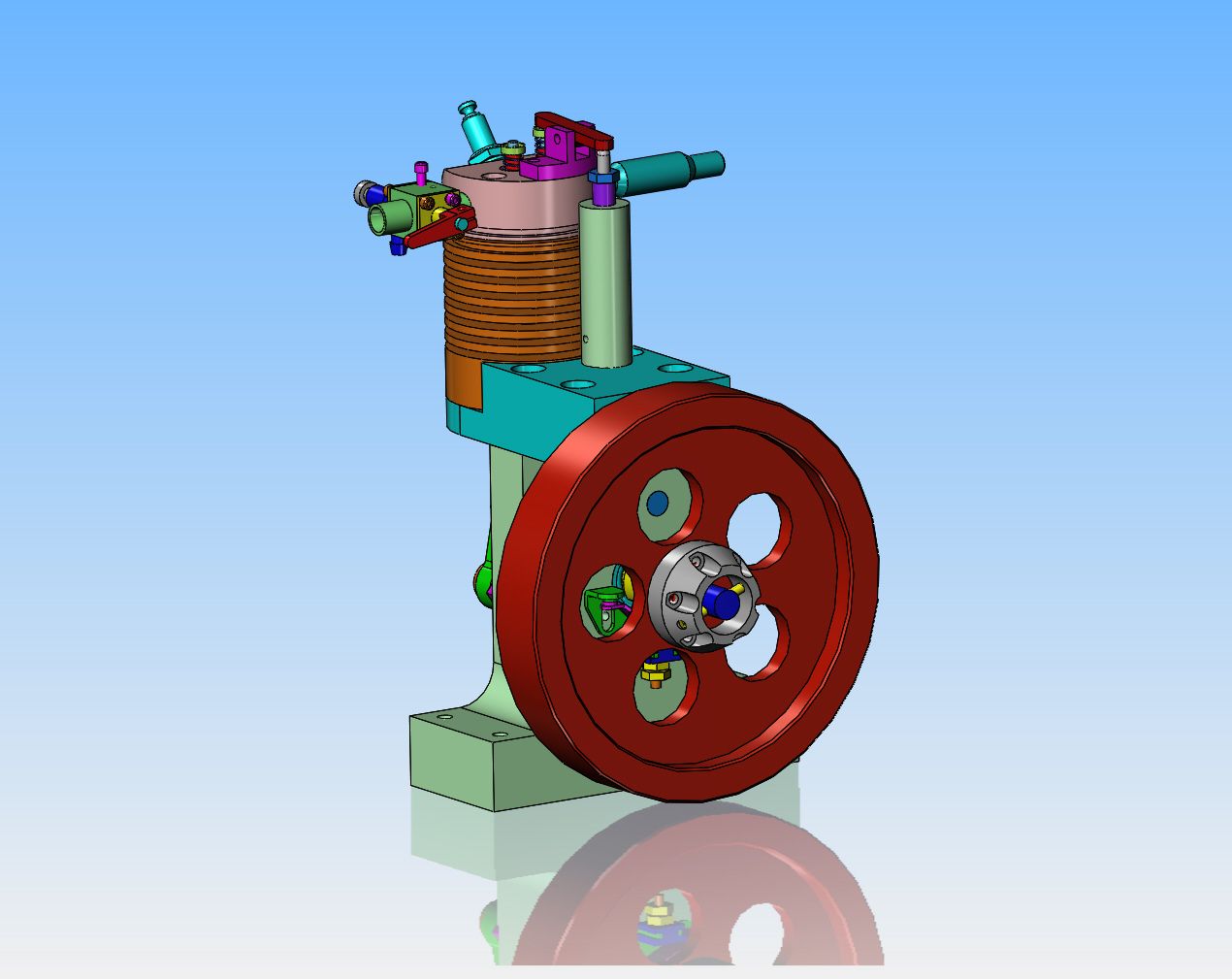


Very cool!
Unfortunately my build of your vertical engine just came to a screeching stop (literally). Looks like one of the spindle bearings just gave out on my Bridgeport. Now I have to figure out whether I'm just going to do the quick repair - fix the spindle or do a full rebuild which is going to take me a couple of months.
Unfortunately my build of your vertical engine just came to a screeching stop (literally). Looks like one of the spindle bearings just gave out on my Bridgeport. Now I have to figure out whether I'm just going to do the quick repair - fix the spindle or do a full rebuild which is going to take me a couple of months.

$40.02
$49.99
Becker CAD 12 3D - professional CAD software for 2D + 3D design and modelling - for 3 PCs - 100% compatible with AutoCAD
momox Shop

$519.19
$699.00
FoxAlien Masuter Pro CNC Router Machine, Upgraded 3-Axis Engraving All-Metal Milling Machine for Wood Acrylic MDF Nylon Carving Cutting
FoxAlien Official

$12.56
$39.95
Complete Plans for Building Horse Barns Big and Small(3rd Edition)
ThriftBooks-Atlanta

$89.99
Outdoor Wood Boiler Water Treatment Rust Inhibitor- AmTech 300 & Test Kit
Alternative Heating & Supplies

$29.95
Competition Engine Building: Advanced Engine Design and Assembly Techniques (Pro Series)
Amazon.com Services LLC

$99.99
AHS Outdoor Wood Boiler Yearly Maintenance Kit with Water Treatment - ProTech 300 & Test Kit
Alternative Heating & Supplies

$24.99
$34.99
Bowl Sander Tool Kit w/Dual Bearing Head & Hardwood Handle | 42PC Wood Sander Set | 2" Hook & Loop Sanding Disc Sandpaper Assortment | 1/4" Mandrel Bowl Sander for Woodturning | Wood Lathe Tools
Peachtree Woodworking Supply Inc

$39.99
$49.99
Sunnytech Low Temperature Stirling Engine Motor Steam Heat Education Model Toy Kit For mechanical skills (LT001)
stirlingtechonline
![DreamPlan Home Design and Landscaping Software Free for Windows [PC Download]](https://m.media-amazon.com/images/I/51kvZH2dVLL._SL500_.jpg)
$0.00
DreamPlan Home Design and Landscaping Software Free for Windows [PC Download]
Amazon.com Services LLC

$94.99
$109.99
AHS Woodmaster 4400 Maintenance Kit for Outdoor Wood Boiler Treatment
Alternative Heating & Supplies

$24.99
$27.99
HOZLY 5PCS/Lot ISO30 Tool Holder Clamp Flame Proof Rubber Claw CNC Machines Automatic Tool Changer
HOZLY
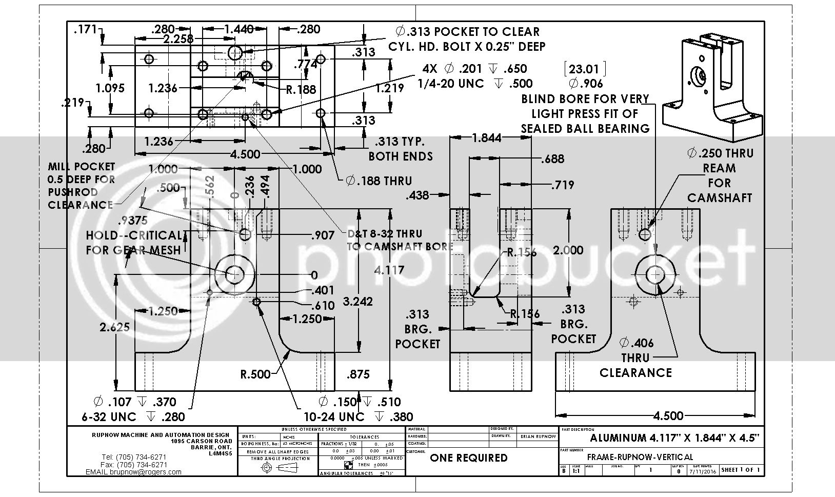
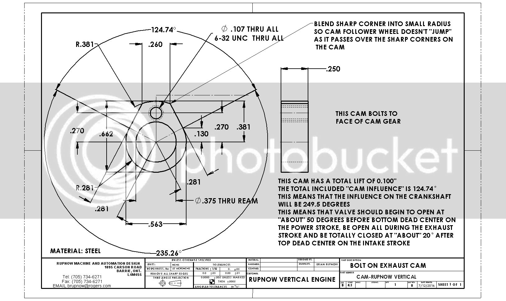
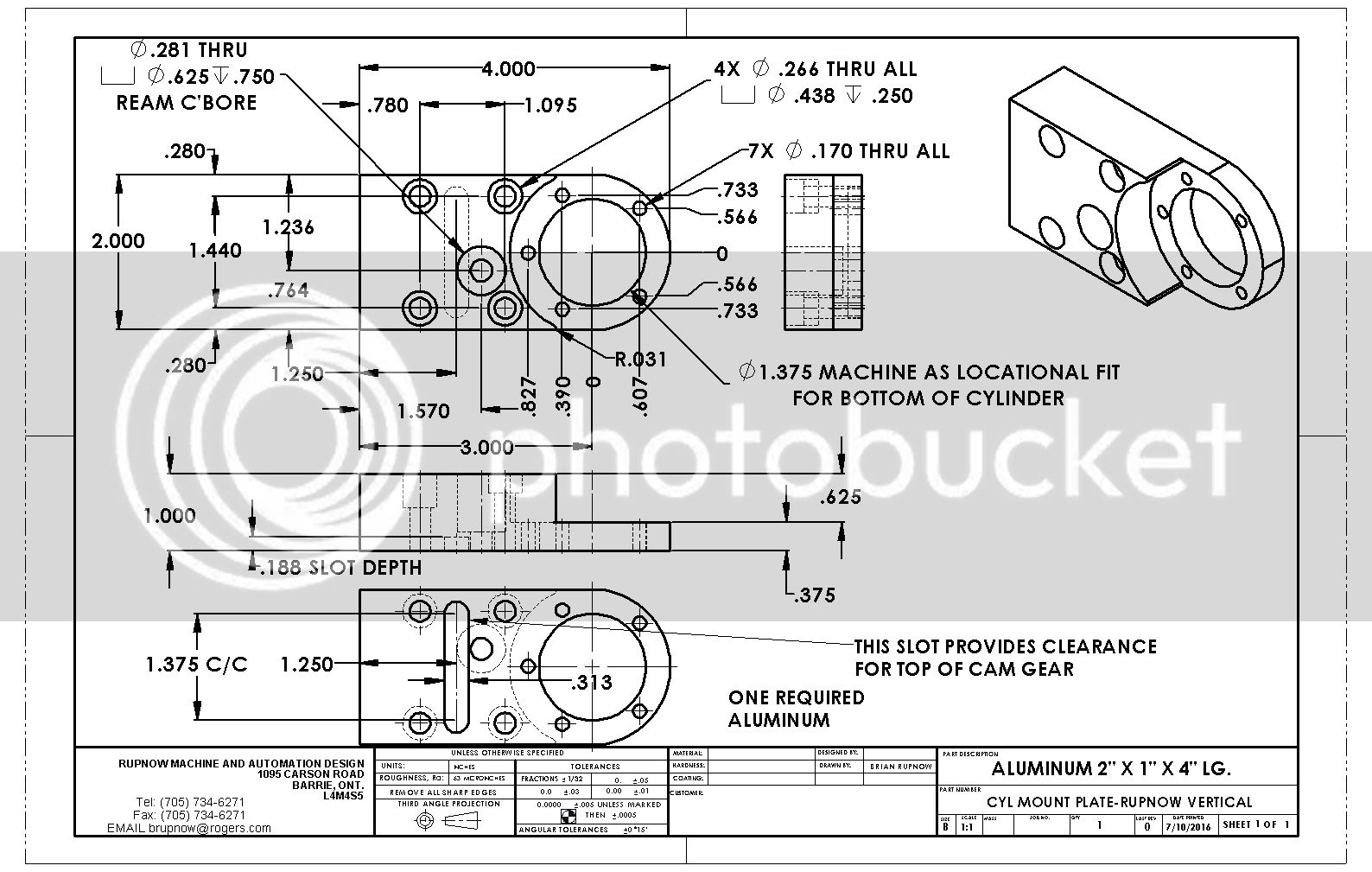
If you think this drawing is a bit crowded, well,---that's because it is!!! However, everything you need to build it is on there. Take your time, and go carefully. There are no 'trick' set-ups required to make this part. EDIT--EDIT--This drawing was changed 11-july-2016 Camshaft hole went from 5/16" diameter to 1/4" diameter.

Last edited:
The .jpeg drawings I have posted are hosted on Photobucket. When you click on the drawing, it will open it in Photobucket. If you can't see enough detail, there is a small magnifying glass with a + sign on it just above the image to the right. If you hover the cursor over it , a pop-up message will say "view image". If you click on the magnifying glass you will get a much larger image and will be able to see more detail.
Last edited:
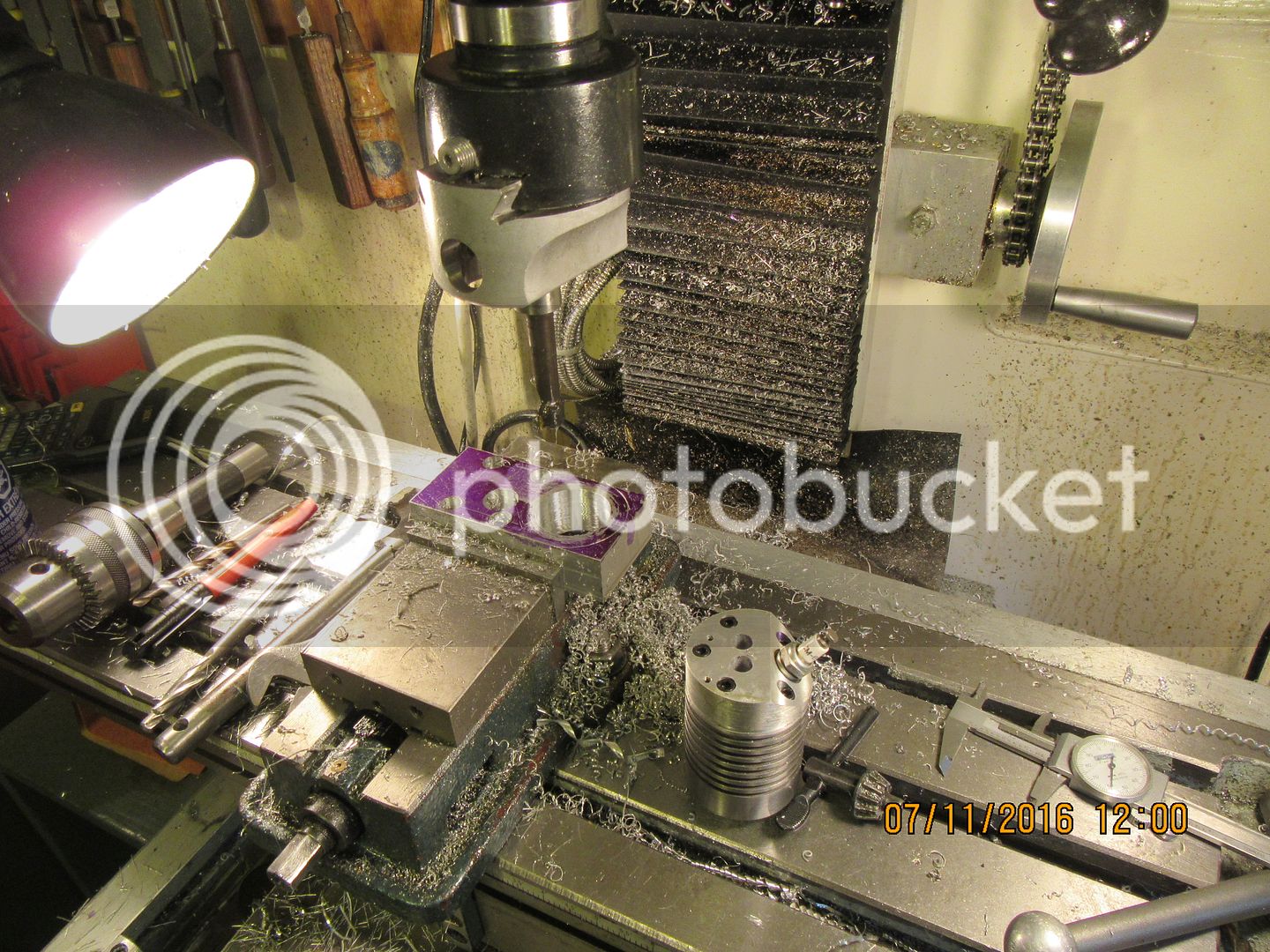
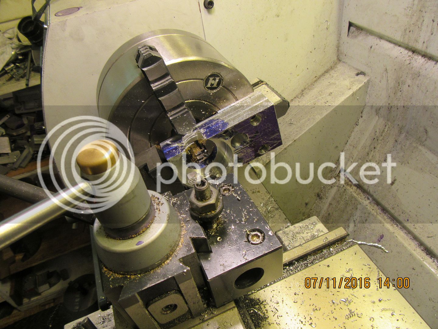
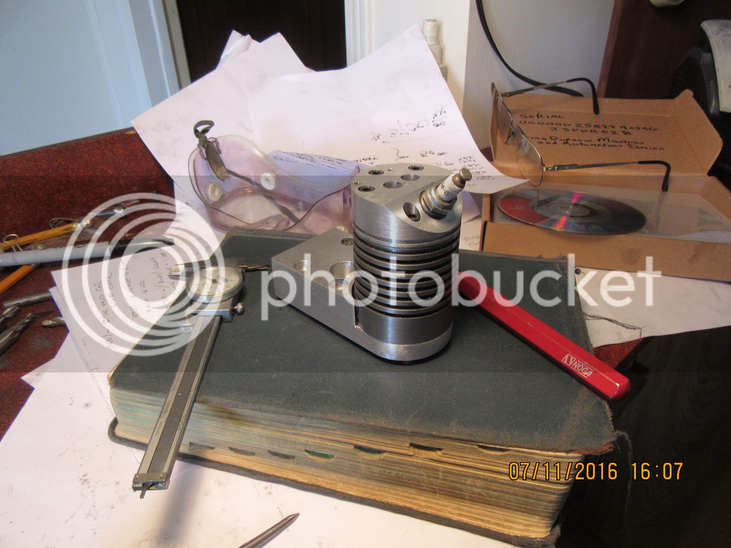
After finishing the center hole, the live center was put back in place and all the grooves turned in the cylinder body to create "fins". My parting off tool is .093" wide, and works excellently for this. All of the grooves were cut using my lathes power cross-feed. (a new and rather frightening experience, but dang, it sure works good!!!) The diameter that fits down into the cylinder support plate was also turned in the same set-up, and then parted off with the live center moved back out of the way--In fact, the only time the part came out of the original set-up was when I flipped it end for end after parting it off and put the small "lead' into the end to make inserting the piston a bit easier. It sure looks "spiffy" with its cylinder head in place!!!
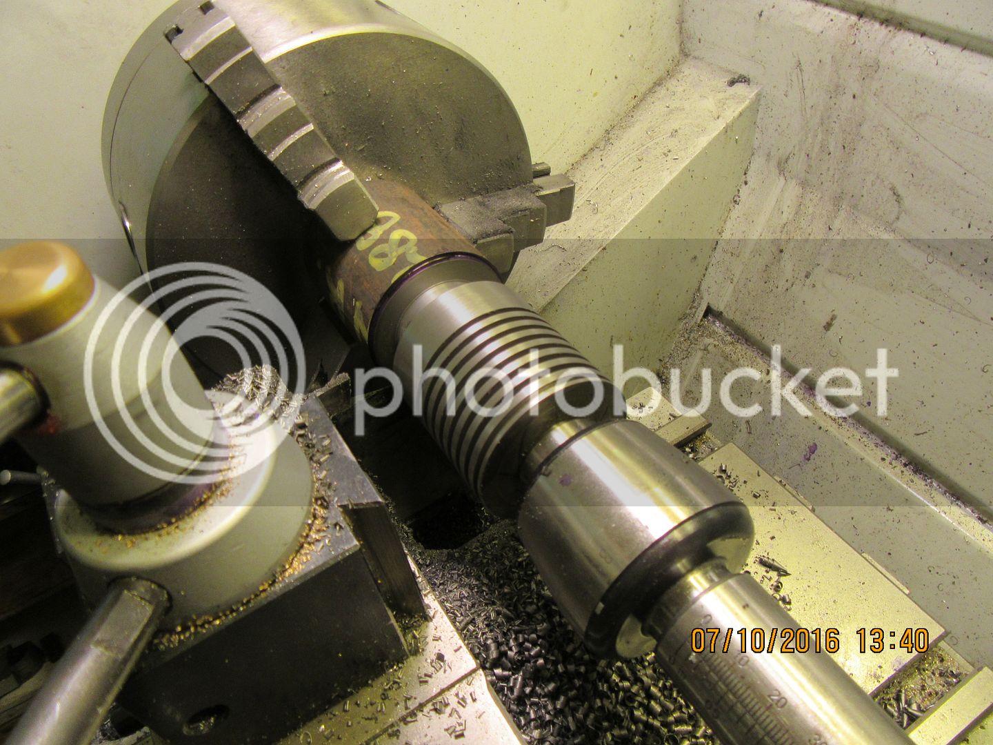
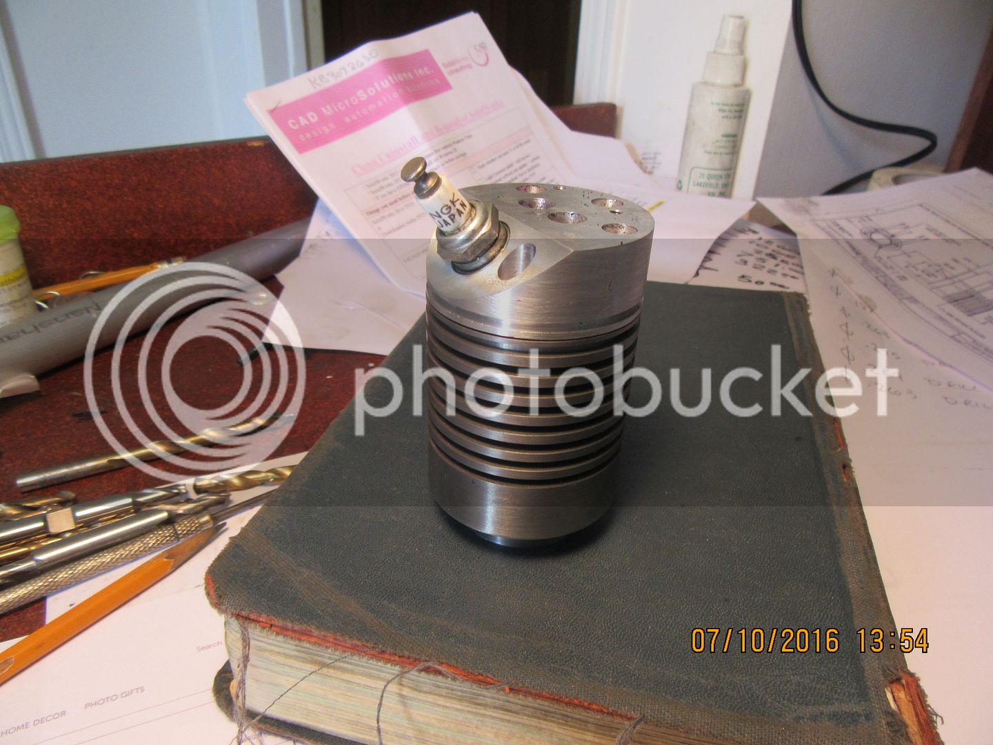


I'm surprised that the cylinder machining went so well. I will put the threaded holes in each end tomorrow. It's funny--I can think of a concept, and model it very quickly. Then after it is modelled, that immediately kick-starts a whole new wave of ideas. I like to keep my engines as "self contained" as possible, and I'm already chasing ideas around in my head of how to mount a gas tank that compliments the engine. It is possible that gas tank, fan, and fan shroud could all be combined. I'm hoping to have a number of people build this engine, so I don't want to do anything too complicated. Right now I have 5 people on board. Two guys in Australia, one fellow in North Carolina, one in Alberta, Canada, and maybe Chuck Fellows.---Brian
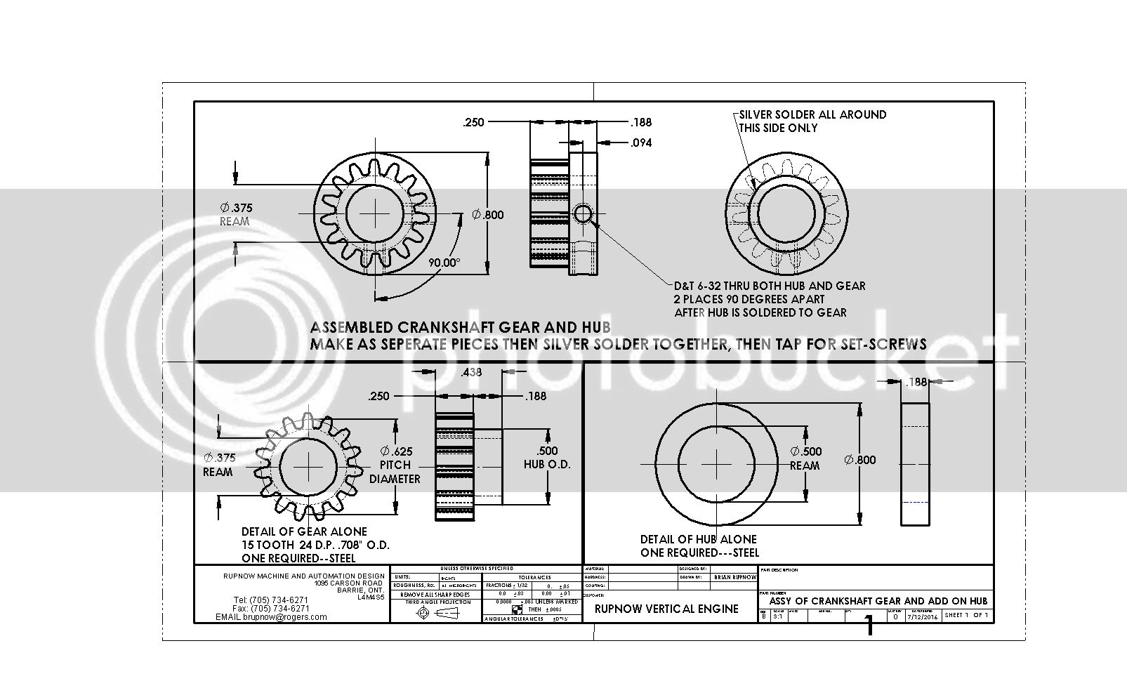
There is going to be a slight bit of "jiggery-pokery" associated with the crankshaft gear, but it's fairly simple and I've used it before with success. The root diameter of the 15 tooth gear is only .500", which means that is the largest diameter hub it can have. When fitted to a 3/8" shaft, that only leaves a 1/16" wall thickness, which is not enough to properly hold a set-screw. You can not make the gear with a larger diameter hub, because there would be no place for "run-out" of the gear cutter.---So---We make a separate hub 0.8" diameter x 3/16" thick and a 1/2" bore, slide it over the existing gear hub, and silver solder it to the gear hub on the side opposite from the gear teeth. Then we drill and tap a pair of #6-32 threads thru the "add on hub" and the original gear hub. We need to do this so that when we go to set the valve timing, we can loosen the set-screws off, rotate both meshing gears to get the cam gear with attached cam into the correct position, then tighten the set screws to locate the crankshaft gear solidly in place on the crankshaft. I will provide a drawing later.
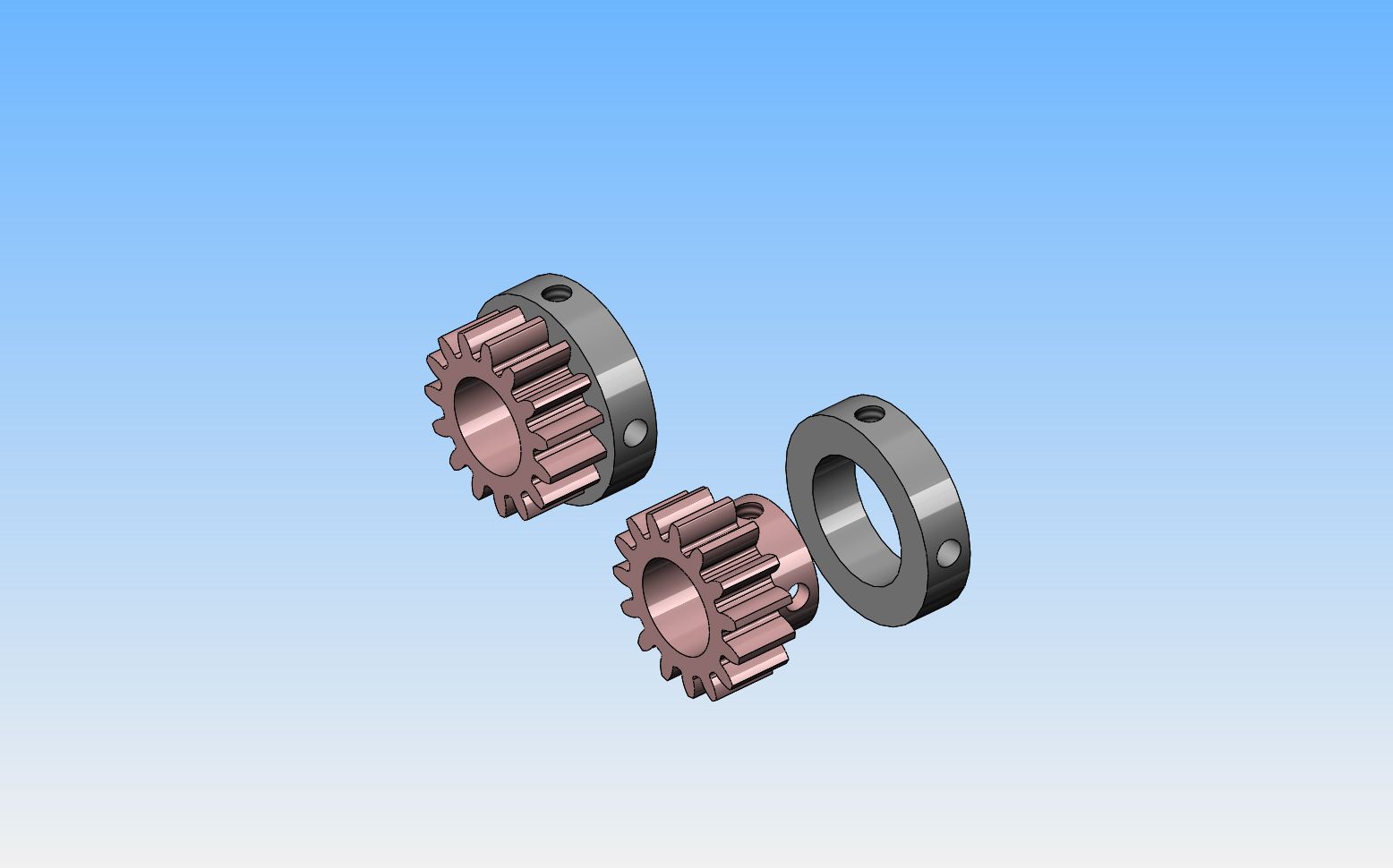

Heads up everybody---I just changed the frame drawing. The hole for the camshaft has changed from 5/16" to 1/4".
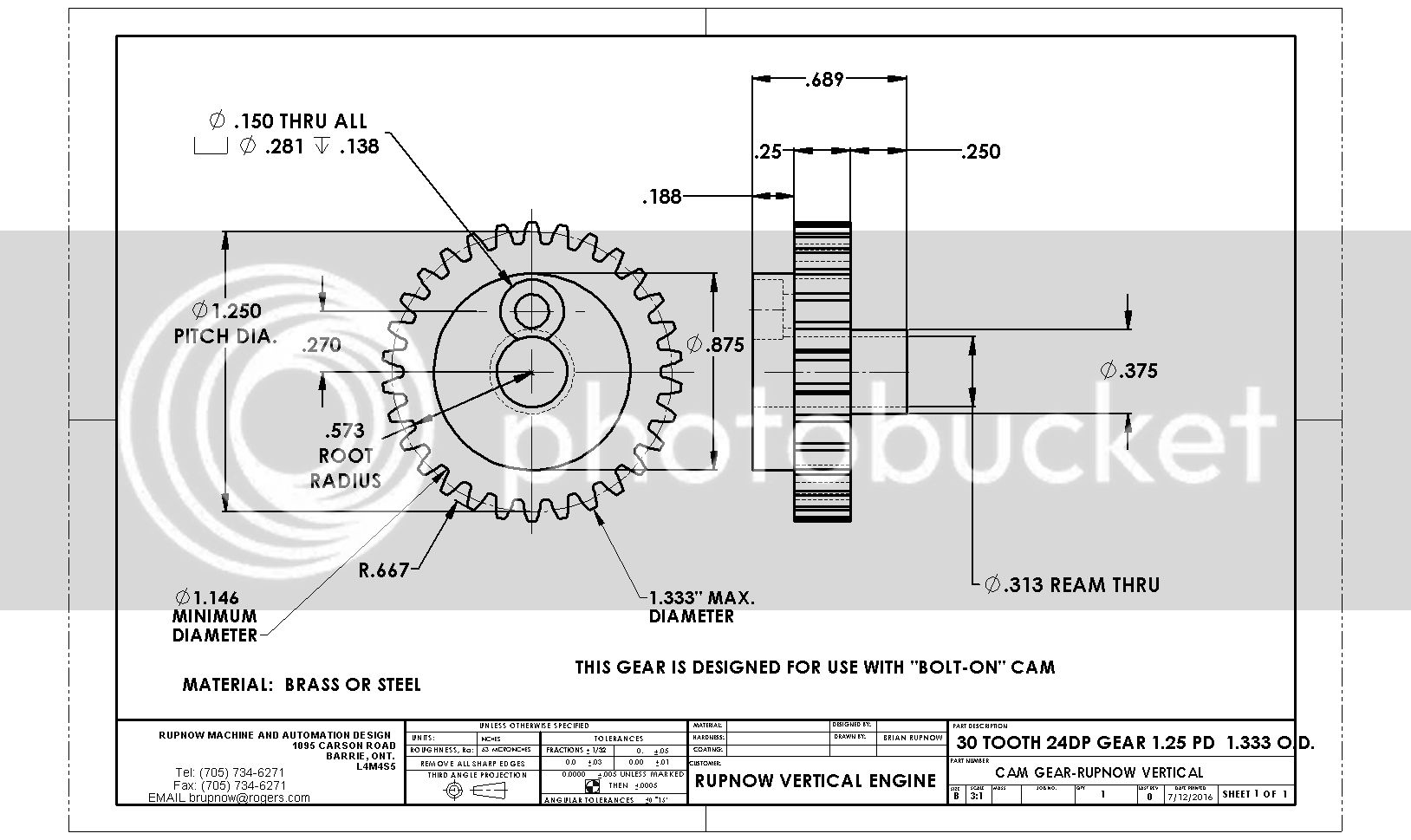
These are the parts that give most novice engine builders fits!! The cam will simply have to be fabricated. The gears can be purchased from the link I gave in an earlier post to Amazon.com and if you have 32 dp gear cutters you can substitute 40 and 20 tooth gears and end up with the same center to center distances.


Not a lot accomplished today. Gathered up a bunch of grandchildren and spent the afternoon in Lake Simcoe. It's 85 degrees F here with high humidity. I'm setting here with a glass of lemonade and coconut rum, deciding how to best tackle the main frame of this beast.--I did at least accomplish one thing this morning--bought the material for the frame and replacements for all the drills I burned up working on that 304 stainless steel customer job.
Dang, I'm tired!!! There is a full 8 hours of machining in the main frame of this engine. Non of it is horribly difficult machining, but man, there's a lot of it. If anybody is ready to start machining their build of this engine right now, email me at [email protected] and I will send you pdf files of the parts as I finish building them. The drawings that I post on here thru Photobucket are not that easy to read or to print. They are preliminary drawings and are 99% correct. As I build the parts, if I see anything fishy on the drawings I change it and resave it. It is from these final corrected drawings that I make my pdf files. There will be a very large package of final drawings saved as pdf files and saved on a web hosting site that you can download them from, but that might not be for a month or two down the road.----Brian
Similar threads
- Replies
- 0
- Views
- 720
- Replies
- 11
- Views
- 896
- Replies
- 2
- Views
- 2K




![MeshMagic 3D Free 3D Modeling Software [Download]](https://m.media-amazon.com/images/I/B1U+p8ewjGS._SL500_.png)


