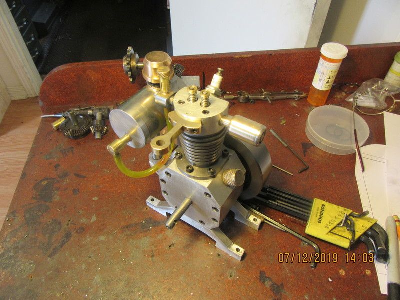
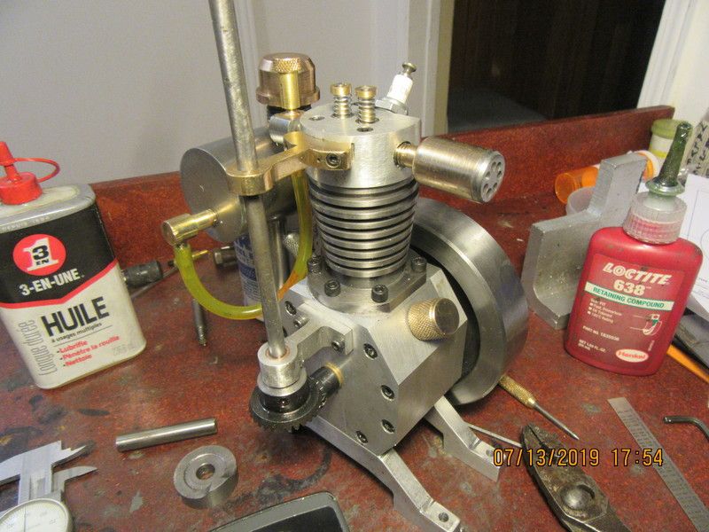
Verical hit and miss engine

Home Model Engine Machinist Forum

Help Support Home Model Engine Machinist Forum:

This site may earn a commission from merchant affiliate links, including eBay, Amazon, and others.
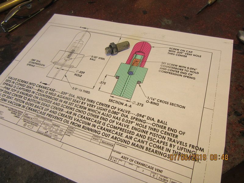
A quick look at a crankcase valve and description of how it operates.
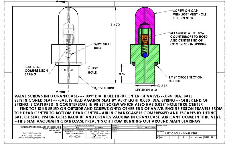
5MWFJO.jpg
 
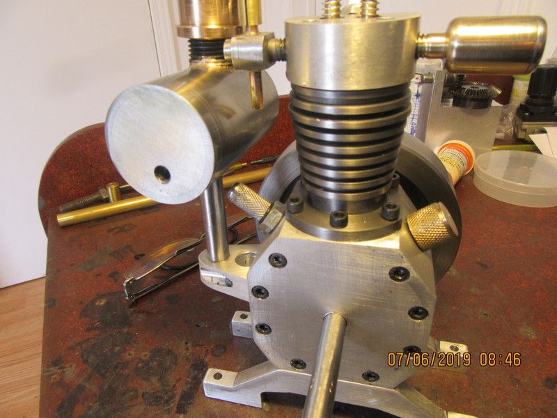
The crankcase vent doesn't look all that impressive, but it's made and installed. At the last minute before I started to machine anything, I realized that I could use a 3/8" bolt for the main body. The head size was correct and I could thread it right up to the underside of the head and then cut it to length. I did that, but drilled out the center to 1/4" and threaded the end of a brass rod both externally and internally, then loctited it into the bolt. The knurled screw on cap ended up being made from cold rolled steel, because I have lots of that. I won't know how well this is going to work until I get the engine running. I can vary the spring pressure on the ball by tightening or loosening the set screw that the end of the spring fits into.
qSH0tU.jpg

i8W0x5.jpg
 
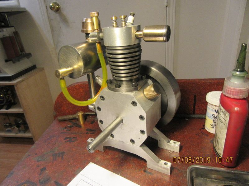
The gas tank plumbing is finished, and with that I'm going to ride off into the sunset. There is nothing left to do until my gears and piston rings come in. Will post some more after I get all the bits and pieces.
k1Cinm.jpg
 
Thanks Ray. That is a lot of parts. I never have pictures like that, as I assemble things as I build them. I know that some people will completely disassemble an engine for polishing or painting and then reassemble the engine. By the time I'm finished building an engine, I don't have the will to tear it all apart again. I want to proceed directly to seeing if the engine will run.
 
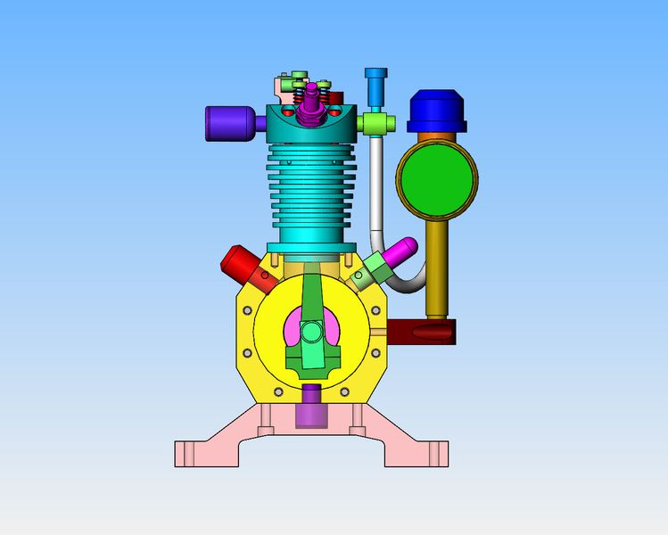
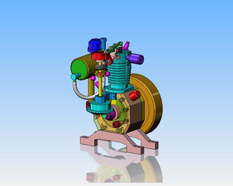
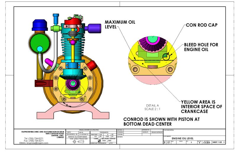
Today we're not machining anything much. I have been thinking about engine oil levels and a dipstick. This view, with some of the near side pieces hidden, shows the position of the crankshaft and con rod with piston at bottom dead center. I'm thinking that the oil level should be such that it comes up to the centerline of the big end of the conrod and not any higher, when the engine is "at rest" with crankshaft in the position shown. If anyone has a different idea for oil level, please let me know. Secondly, there is nowhere inside the crankcase for a dipstick. The entire cavity is filled with crankshaft and con rod as the crankshaft travels thru 360 degrees. I have the beginning of an idea---Right now the oil drain plug is a solid piece of steel screwed into the bottom of the crank case. If I ran a pipe horizontally from the oil drain plug, then a 90 degree elbow "up", and then a short piece of vertical pipe, the oil level in that short vertical pipe would be the same as the oil level in the engine when the engine was not running. This would let me have a screw on cap that would be air tight. On the outboard end of the screw on cap, I would solder a dipstick. I want the crankcase to be sealed so the vacuum fitting can do it's job properly and maintain a semi vacuum in the crankcase. I don't want a separate dipstick which would surely get lost. Making the screw on cap and the dipstick one piece seems like a good plan to me, but I'm open for suggestions. What do you think? (This picture does not show what I am talking about re: dipstick.) It shows the engine in it's current state with only a screw in plug in the bottom of the crank case.
ZukmOV.jpg
 
Hi Brian
Nothing at all wrong with the dipstick idea. I recall some of the old engines just used a filler with a small resevoir with a level incorporated set at the required level. You simply remove the cap and fill till you see oil remain up to the filler level. You checked before starting and top up if necessary.
You might not want to consider this one but some even simply used an overflow. Remove the filler cap which is set at the full level. Fill till it overflows then replace the plug. This one was often used in auto transmissions.
 
I checked the idea of a sight glass, and I could fit one. This option was suggested by Jason from the U.K. Just tap one of the sideplates ( it would have to be on the governor side) at the level you want the oil to be. Take out the bolt, fill engine with oil until it starts to run out the bolt hole, then put the bolt back in. It is simple and gets the job done. A 5/16" shcs with a fibre washer will work just fine. Thank you Jason.---Brian
t1unuz.jpg
 
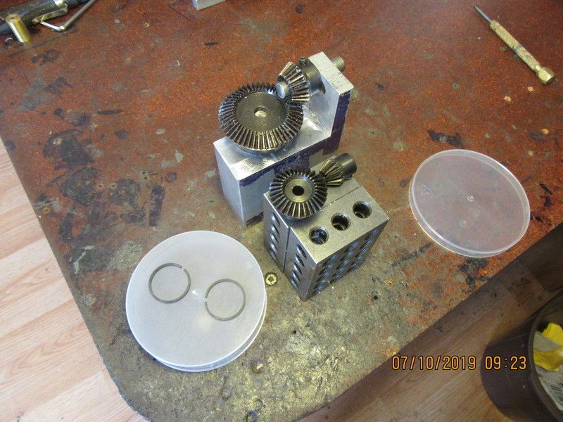
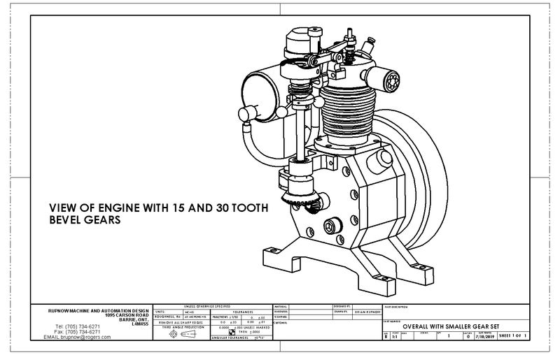
Today my smaller gear set arrived, along with my piston rings. The smaller gears seem to be just about perfect size-wise. The large gear set was 20 and 40 teeth---the smaller set are 15 and 30 tooth. The piston rings appear to be fine, but they will need a bit of clean up on the top and bottom, because they appear to be "as heat treated" with no farther work done on them.
r6SVSm.jpg
 
I modelled the new gears and adjusted everything in the governor train to match them, and I like the new proportions much better. The new gears have a bore of 6 mm, which is slightly less than 1/4". Since I don't have any metric shafting, I will either use 1/4" and turn the ends of the crankshaft and cam shaft down to 6 mm or else run a 1/4" reamer thru the gears. I have gotten lucky and don't have to machine away any of the fins on the cylinder, as the governor balls will clear them with my new set-up. The crankshaft will be 3/8" diameter and the camshaft will be 1/4". I will have to sleeve the bore on the face cam, as it is currently bored for a 3/8" shaft.
6KOwLY.jpg
 
Bob--It looks like gold, and when you go to buy any, it seems to cost about as much!! Some good hearted soul sent me two 12" square x 1/4" thick plates of brass about 5 years ago because they liked my posts, and I'm still nibbling away at them.
 
Today I made the lower camshaft bracket along with it's oilite bronze bushing. The gears mesh very nicely. For all of you who have made engines or machinery with gears which must mesh correctly, you will know that what sounds very simple has much more to it!!! The shaft which was used for alignment may very well become the cam shaft. My original plan for the top bracket was to have two pieces of brass silver soldered together. One to support the cam shaft and the other to be a pivot for the rocker arm. I'm thinking I may change that to two pieces bolted together. If I can do that, I can make the pivot part from aluminum.
gnVaPt.jpg
 
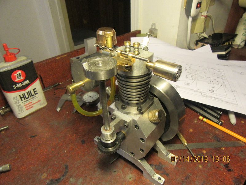
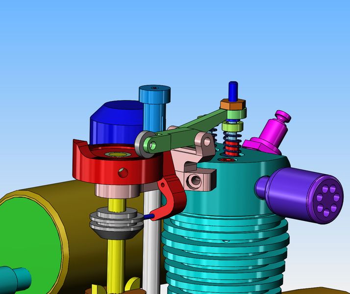
Today I made the very TINY rocker arm pivot. (The part with the drill stuck thru it.). It is my hope that I can bolt the rocker arm pivot to the brass bracket it is setting on top of. But, there is a catch---when the rocker arm is installed, one end of it has to be perfectly centered over the exhaust valve, and the other end must hold the contact roller perfectly in line with the center of the track on the face cam. Being old and filled with wisdom, I know damned well that if I just arbitrarily bolt the rocker pivot to the top cam shaft bracket, that's never going to happen. So, I won't do any bolting until I have built the rocker arm and installed it and the pivot shaft in place and then, with everything lined up "dead nuts", I will proceed to clamp things together and drill/tap the holes for the bolts which hold the rocker pivot in place. Tomorrow I'm off to the hospital for a cataract operation, so I'm not sure when I will post again.---Brian
yjOMrL.jpg

XiYszU.jpg
 
Today I made the very TINY rocker arm pivot. (The part with the drill stuck thru it.). It is my hope that I can bolt the rocker arm pivot to the brass bracket it is setting on top of. But, there is a catch---when the rocker arm is installed, one end of it has to be perfectly centered over the exhaust valve, and the other end must hold the contact roller perfectly in line with the center of the track on the face cam. Being old and filled with wisdom, I know damned well that if I just arbitrarily bolt the rocker pivot to the top cam shaft bracket, that's never going to happen. So, I won't do any bolting until I have built the rocker arm and installed it and the pivot shaft in place and then, with everything lined up "dead nuts", I will proceed to clamp things together and drill/tap the holes for the bolts which hold the rocker pivot in place. Tomorrow I'm off to the hospital for a cataract operation, so I'm not sure when I will post again.---Brian
yjOMrL.jpg

XiYszU.jpg

Good luck with surgery
 
Today I made the very TINY rocker arm pivot. (The part with the drill stuck thru it.). It is my hope that I can bolt the rocker arm pivot to the brass bracket it is setting on top of. But, there is a catch---when the rocker arm is installed, one end of it has to be perfectly centered over the exhaust valve, and the other end must hold the contact roller perfectly in line with the center of the track on the face cam. Being old and filled with wisdom, I know damned well that if I just arbitrarily bolt the rocker pivot to the top cam shaft bracket, that's never going to happen. So, I won't do any bolting until I have built the rocker arm and installed it and the pivot shaft in place and then, with everything lined up "dead nuts", I will proceed to clamp things together and drill/tap the holes for the bolts which hold the rocker pivot in place. Tomorrow I'm off to the hospital for a cataract operation, so I'm not sure when I will post again.---Brian
yjOMrL.jpg

XiYszU.jpg
 

Latest posts

Back
Top