Okay, the fix is in. I had to make a new con rod and cap, watched my dimensions much more closely, and the rod fits in now and the engine will rotate thru 360 degrees. It does clear now---not by very darn much, but a miss is as good as a mile. I'm stiff and sore today from so much playing yesterday. I need two gaskets for above and below the crankcase and two head-gaskets. I think I will be a lazy hound and make my gaskets this afternoon.----Brian

You are using an out of date browser. It may not display this or other websites correctly.
You should upgrade or use an alternative browser.
You should upgrade or use an alternative browser.
Upshur's opposed twin engine
- Thread starter Brian Rupnow
- Start date


Help Support Home Model Engine Machinist Forum:
This site may earn a commission from merchant affiliate
links, including eBay, Amazon, and others.
Brian,
Take it easy and listen to you body. Take plenty of brakes until you get every thing working correctly again.
Cheers
Amdrew
Take it easy and listen to you body. Take plenty of brakes until you get every thing working correctly again.
Cheers
Amdrew
A little change in the game plan this afternoon. I had assembled my valve cages, valves, valve springs and spring retainers a couple of weeks ago, and at that time I thought--"Jeez, there isn't much movement in those valves before the top spring retainer hits the valve cage and won't move any farther." My cams have 0.072" of lift, and the valve has to be able to move farther than that, or bad things will happen very quickly. So, this afternoon I disassembled the valves and turned 0.050" away from the underside of the spring retainers. (This minor diameter on the spring retainer only has one job---to center the spring in the valve retainer). I machined 0.050" from the length of the minor diameter and still had 0.031" to center the springs. After reassembly I checked the free movement of each valve with my Vernier and each spring can now move slightly over 0.100" before it touches the valve cage.--disaster averted.---I'll make my gaskets tomorrow.
HAH!!!---Milestone day today.--I drove my truck for the first time since my knee surgery. Needed a couple of new hex wrenches, so drove to my nearest tool supplier and purchased them. Wasn't any problem driving,---hardest part was getting my gimpy old arse up into the truck seat. My truck sets up fairly high, and has a running board to help you get up there. I needed both legs and my cane, but I made it.
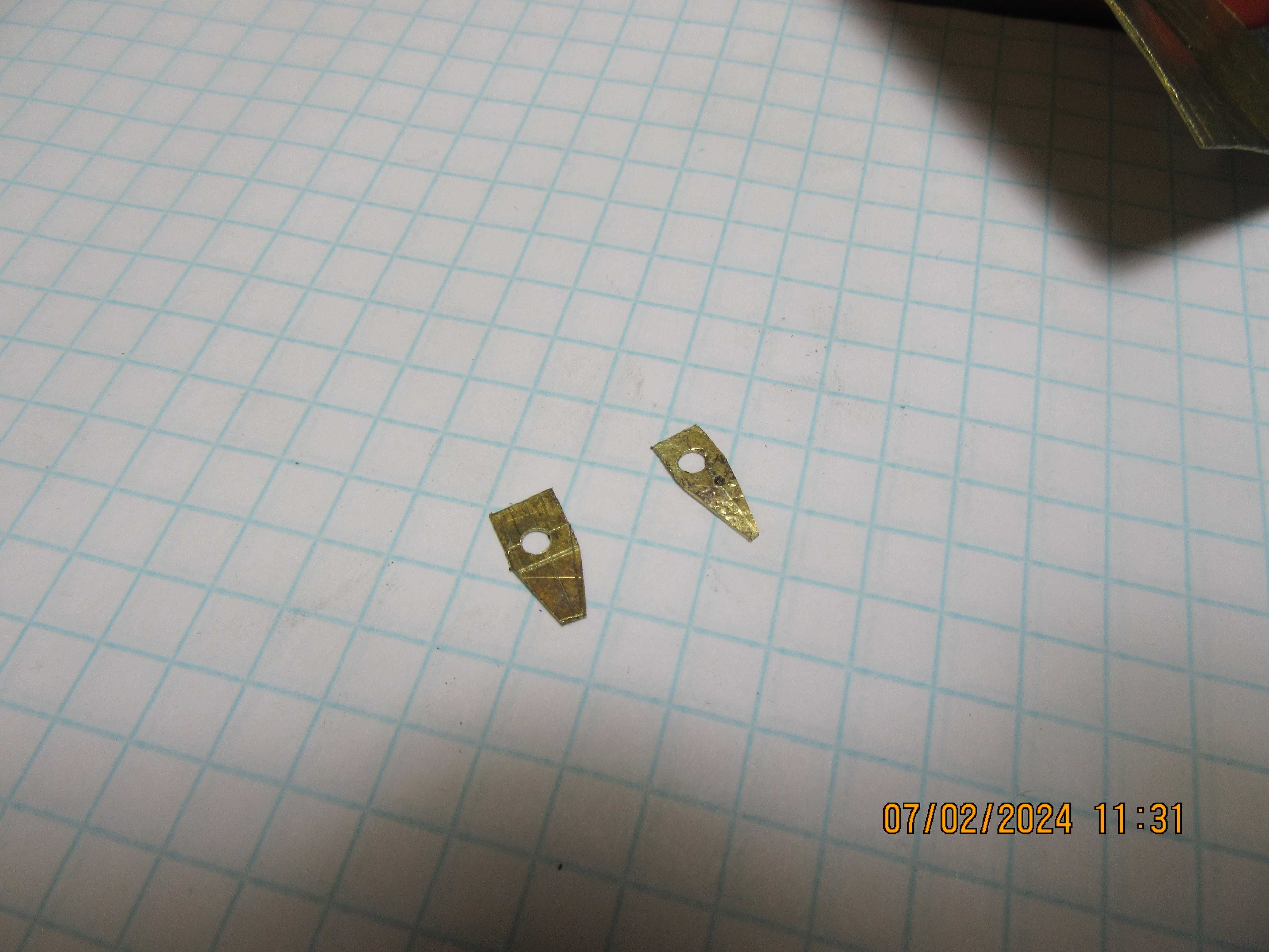
These two rather horrible little parts are "oil slingers" which bolt to the underside of the con rod caps and sling oil all over the inside of the crankcase when the engine is running. They are horrible because non of my machinery is really intended to make parts this small. So, by default, they are made with sheet metal "snips" and are irregular and ugly. The only good thing about them is that they are down inside the engine where nobody will ever see them.
Yes they will not be seen in the engine, but we all know that they are there 
Cheers
Andrew
Cheers
Andrew


$188.98
TM NEXDYNAMI RE41157 Water Pump Compatible With/Replacement For/John Deere 6200 7400 6300 6600 6500 6400 7220 7600 7200 RE41157
VIVID MARKET CORPORATION


$154.76 ($1.38 / oz)
Replacement Combustion Chamber Kit, Burnham V8 and V8H, 1-6 Sec, 108136-01, 1129
Plumbing Planet

$426.53
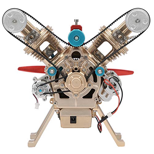
DM14 Engine Build Kit, Metal Engine Build Model Great Metal Material for Engineer for Factory
Easoger Official


$109.99
AmTech300 - Boiler Treatment Professional Strength (Rust Inhibitor For Outdoor Wood Boilers)
Alternative Heating & Supplies


$40.02
$49.99
Becker CAD 12 3D - professional CAD software for 2D + 3D design and modelling - for 3 PCs - 100% compatible with AutoCAD
momox Shop

$39.99
$49.99
Sunnytech Low Temperature Stirling Engine Motor Steam Heat Education Model Toy Kit For mechanical skills (LT001)
stirlingtechonline

$94.99
$109.99
AHS Woodmaster 4400 Maintenance Kit for Outdoor Wood Boiler Treatment
Alternative Heating & Supplies


$649.00
$699.00
FoxAlien Masuter Pro CNC Router Machine, Upgraded 3-Axis Engraving All-Metal Milling Machine for Wood Acrylic MDF Nylon Carving Cutting
FoxAlien Official


$29.95
Competition Engine Building: Advanced Engine Design and Assembly Techniques (Pro Series)
Amazon.com Services LLC


$99.99
AHS Outdoor Wood Boiler Yearly Maintenance Kit with Water Treatment - ProTech 300 & Test Kit
Alternative Heating & Supplies


![MeshMagic 3D Free 3D Modeling Software [Download]](https://m.media-amazon.com/images/I/B1U+p8ewjGS._SL500_.png)


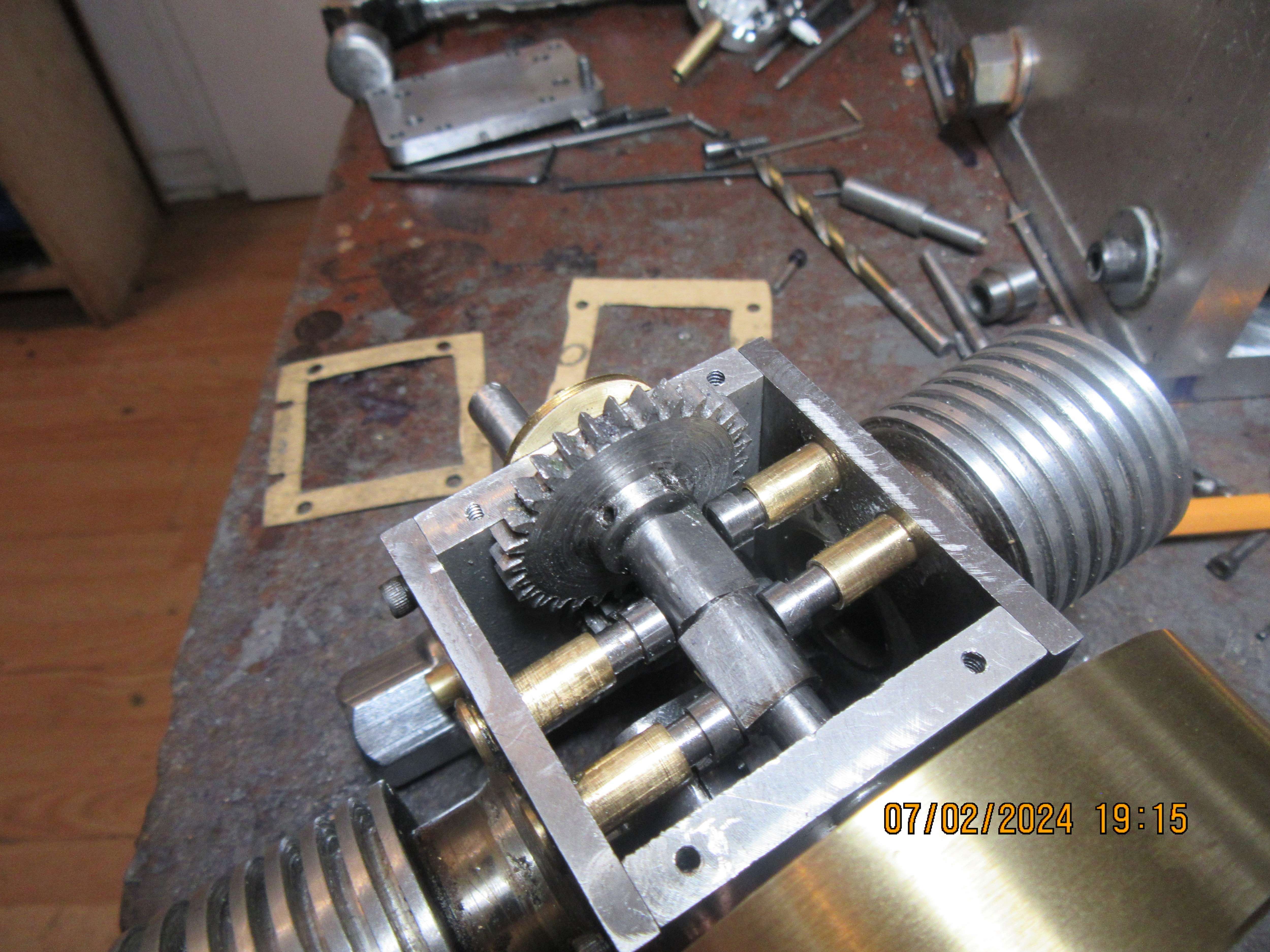
If you look closely you will see that one of the valve tappets is very close to the hub of the large gear.--it actually was too close. It hung up on the hub of the gear rather than following the cam like it was meant to. This meant removing the gear, drilling new set screw holes closer to the gear face, and machining away 0.040" from the face of the hub. This was something I discovered while adding those horrible oil slingers to the connecting rod caps. All is reassembled now, and I have made the gaskets for both top and bottom of the crankcase. I am going to use some type of "form a gasket from a tube" on the four corners of the crankcase that bolt together.---I'm waiting until tomorrow to do this, because adding any kind of gasket goo is hopefully the last step. I will sleep on it and make sure that I don't have anything else to machine before doing the gasket thing.
Last edited:
I gotta ask. Not to provoke you, but did you follow Pusher’s plans? I don’t know anyone that’s built this engine have these issues.???If you look closely you will see that one of the valve tappets is very close to the hub of the large gear.--it actually was too close. It hung up on the hub of the gear rather than following the cam like it was meant to. This meant removing the gear, drilling new set screw holes closer to the gear face, and machining away 0.040" from the face of the hub. This was something I discovered while adding those horrible oil slingers to the connecting rod caps. All is reassembled now, and I have made the gaskets for both top and bottom of the crankcase. I am going to use some type of "form a gasket from a tube" on the four corners of the crankcase that bolt together.---I'm waiting until tomorrow to do this, because adding any kind of gasket goo is hopefully the last step. I will sleep on it and make sure that I don't have anything else to machine before doing the gasket thing.
I followed most of the plans. Some of the stuff I changed a bit, but 99% followed the plans. The plans are very well done, and I wouldn't throw stones at Upshur for anything I have found a bit fishy. ----Brian
- Joined
- Jan 4, 2011
- Messages
- 1,429
- Reaction score
- 397
I build the engine several years ago and I also found that the cam hit the connecting rod if the timing was wrong and I also had to shave some off from the gear.
Gordon---Thank you.--And---speaking of timing---I want this engine to turn clockwise when viewed from the "non carburetor side". (This is opposite to what Upshur plan calls for). I am making an assumption here. Since the cylinders are exactly opposite one and other, then wouldn't the two cams be positioned exactly opposite to each other? The plans from Upshur show the cams at 90 degrees offset on their assembly drawing, but I don't think that is correct. I've never built an engine with a cam arrangement like this one has, where one cam operates the exhaust valve on both cylinders and the other cam operates the intake valve on both cylinders. I don't fully understand the Upshur valve timing instructions. If I set a cam to begin opening the intake valve 15 degrees before the piston reaches top dead center, then by default doesn't that begin opening the intake on the other side (180 degrees away) 15 degrees before top dead center as well.---Same deal for the cam that operates the exhaust valve on both of the cylinders. if I set it to begin opening the exhaust valve on one cylinder 40 degrees before the piston reaches bottom dead center, then by default doesn't that begin opening the exhaust valve on the other cylinder (180 degrees away) 40 degrees before the piston reaches bottom dead center as well? I'm bit confused here.---Brian
Suggest you read the drawings again, cams are not at 90deg on the drawings I have
You also did not follow them regarding the mounting of the cam gear so the clash is of your own making, there is no boss on his gear.
Are you going to leave all the burrs on the cam gear and other parts? They could come off when running and chew up things like O rings and then work their way to teh valves and stop them closing. You will then be back to your problems of low or no compression
I remove the burrs before running the engine. All the pictures I have posted are
in progress " shots of the build.--Brian

in progress " shots of the build.--Brian
I've never built an engine with a cam arrangement like this one has, where one cam operates the exhaust valve on both cylinders and the other cam operates the intake valve on both cylinders.
The way you have the lobes arranged is very strange
It's only a 1 cylinder engine on each side so the lobe angle will be somewhere around 110 degrees
I though this rang a bell I raised this issue weeks ago and said you looked to have about 50thou error due to deviating from the Upshur designA little change in the game plan this afternoon. I had assembled my valve cages, valves, valve springs and spring retainers a couple of weeks ago, and at that time I thought--"Jeez, there isn't much movement in those valves before the top spring retainer hits the valve cage and won't move any farther." My cams have 0.072" of lift, and the valve has to be able to move farther than that, or bad things will happen very quickly. So, this afternoon I disassembled the valves and turned 0.050" away from the underside of the spring retainers. (This minor diameter on the spring retainer only has one job---to center the spring in the valve retainer). I machined 0.050" from the length of the minor diameter and still had 0.031" to center the springs. After reassembly I checked the free movement of each valve with my Vernier and each spring can now move slightly over 0.100" before it touches the valve cage.--disaster averted.---I'll make my gaskets tomorrow.
https://www.homemodelenginemachinis...-opposed-twin-engine.36037/page-9#post-411589
Without a word of exaggeration, Permatex Form a Gasket is the most evil **** I have ever worked with. It does the job, but it's on my engine, my hands, my shirt, my tools and probably in places I haven't even looked yet!!!
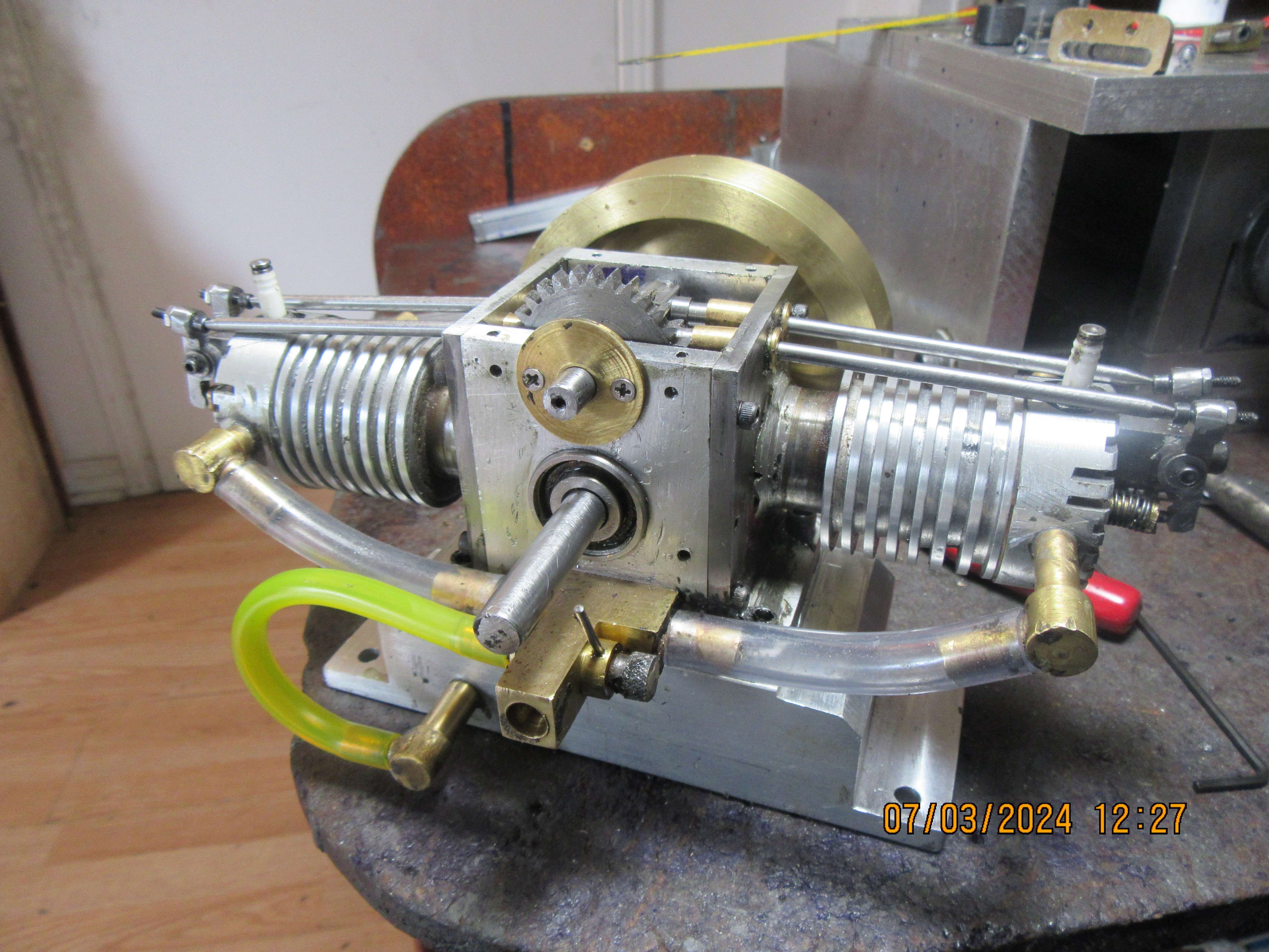
I have reached a point on this engine, where mechanically it is finished and ready to run. I still have to sort out the distributor but I don't see that as a major problem. I blew up the digital copy I have of the engine plans, and you are right---the cams are not at 90 degrees as I thought. They appear to be arranged somewhere between 102 and 110 degrees apart. I'm having a hard time getting my head around this.---Would greatly appreciate it if somebody walked me thru this firing sequence.----Brian
Last edited:
- Joined
- Jan 4, 2011
- Messages
- 1,429
- Reaction score
- 397
Does this help? It is confusing.


Gordon---thank you so much. I will use that timing diagram to set my cams.---Brian

Similar threads
- Replies
- 413
- Views
- 59K
- Replies
- 25
- Views
- 6K
- Replies
- 27
- Views
- 4K
- Replies
- 61
- Views
- 12K