Tips for Arduno software for Rotary Table Controllers

Home Model Engine Machinist Forum

Help Support Home Model Engine Machinist Forum:

This site may earn a commission from merchant affiliate links, including eBay, Amazon, and others.
I've been thinking about Carl's problem which I'm sure is related to memory overflows from a memory leak. Typically, leaks manifest when scode is called repeatedly. If this is the case it has to be in the external classes I'm using for forms and fields. I find the best way to solve problems is to leave them alone for a while to let the brain work its way though it.

I'm wondering if forms are not clearing themselves correctly when exiting a procedure. In the examples, all forms and fields were global variables and I moved them to procedures to free up memory. The printDivideVals is called every time you do a division so it is a very busy piece of code. It contains a form that is never used but I added it to format an angle. I'm wondering if the Field is not being erased correctly in exit.

I had some problems when testing 20 odd divisions this morning as afterwards I could not enter the Home menu so maybe this was enough for me to see the memory leak manifest itself on my system.


Carl, I'm wondering if you add this to the end of the procedure
Code:
  tempForm.removeField(&tempField);

as shown here.
Code:
void printDivideVals(int iDiv,long iAngle)
{
  Form tempForm(lcd);
  DegreeField tempField(tempForm, "", 360, DEGREEFIELD_READ_WRITE); // Just using this to convert to degrees

  lcd.clear();
   lcd.setCursor(0,0);
   lcd.print("Div: ");
   lcd.print(iDiv);
   lcd.print(" of ");
   lcd.print(divisions);
   tempField.setValue(iAngle);
   tempField.printDegrees();
   lcd.setCursor(10,1);
   lcd.print(" / Div"); 
  tempForm.removeField(&tempField); 
}

In theory, the compiler should look after all of this for us but its worth a try. If this solves your problem, I know to go through all of the other procedures and explicitly remove all fields on exit in this way..

Please report back...
 
I've been thinking about Carl's problem which I'm sure is related to memory overflows from a memory leak. Typically, leaks manifest when scode is called repeatedly. If this is the case it has to be in the external classes I'm using for forms and fields. I find the best way to solve problems is to leave them alone for a while to let the brain work its way though it.

I'm wondering if forms are not clearing themselves correctly when exiting a procedure. In the examples, all forms and fields were global variables and I moved them to procedures to free up memory. The printDivideVals is called every time you do a division so it is a very busy piece of code. It contains a form that is never used but I added it to format an angle. I'm wondering if the Field is not being erased correctly in exit.

I had some problems when testing 20 odd divisions this morning as afterwards I could not enter the Home menu so maybe this was enough for me to see the memory leak manifest itself on my system.


Carl, I'm wondering if you add this to the end of the procedure
Code:
  tempForm.removeField(&tempField);

as shown here.
Code:
void printDivideVals(int iDiv,long iAngle)
{
  Form tempForm(lcd);
  DegreeField tempField(tempForm, "", 360, DEGREEFIELD_READ_WRITE); // Just using this to convert to degrees
 
  lcd.clear();
   lcd.setCursor(0,0);
   lcd.print("Div: ");
   lcd.print(iDiv);
   lcd.print(" of ");
   lcd.print(divisions);
   tempField.setValue(iAngle);
   tempField.printDegrees();
   lcd.setCursor(10,1);
   lcd.print(" / Div"); 
  tempForm.removeField(&tempField); 
}

In theory, the compiler should look after all of this for us but its worth a try. If this solves your problem, I know to go through all of the other procedures and explicitly remove all fields on exit in this way..

Please report back...
Ok, here go's Rod...I compiled V9 and the report was. Binary sketich size 26576 bytes (of a 30720 byte maximum).
Ran it defalt with Divisions set to 4 (90 degs) hit go button and stepper starts then stalls. Config/Set speed = 100%. Reduced that to 50%. Speed was fine BUT, it turned 140 degs.

Config/Setup shows Max Hz at 1290 and Min Hz at 1000. Steps per Rv at 640. Half stepping set to 2 on both skitch and driver.

Reset every thing in Setup the same as above and this time it turned 90 degs as it should. Pushed go button again and speed was half first 90 deg turn. WTH?

Inserted tempForm.removeField(&tempField); and recompiled. Set Divisions to 4 again and hit go button. Turned at half speed.

Back to Config/Setup. Speed was at 100%, Max Hz still 1290, Min Hz still 1000, Steps per Rv 640. Back to Divisions set to 4 still. Hit go button and table turned 100 degs.

I had a full head of hair, but, now I'm down to two big bald spots on the sides and a strip of hair down the middle.

Reset every thing and set divisions to 4 and hit go button again. This time it turned 230 Degs and half speed.

I have V5 working great with Speed Set commeted out. Now my fingers are bleeding and my head hutz. Carl
 
Carl,

You better add memory loss to your list of problems beside hair loss and bleeding fingers :eek:
My Arduino UNO has 2k more memory than yours.....
V5 has 489 lines of code
V9 has 972 lines of code
No wonder you are loosing your hair!

I guess though if you have a working solution, its not worth loosing much sleep over.

Whenever I've had strange things happening it's righted itself when I've reduced memory use freeing up more memory for local variables. Its not actually total memory used that is the problem, its whats left for local variables that is the limiting factor. You did not say how much you had left. There is only 2k of this to go round. Sounds like you have an earlier boot loader in your Arduino and probably an earlier version of the IDE which are stealing memory. (I'm on IDE V 1.6.0 and upgrading to it, gave me more memory.)

Yesterday, I set it up with 144 divisions and ran hundreds and hundreds of steps without rebooting and no problems with the software at all. BUT...

My little 60 oz NEMA23, I'm missing steps no matter what I do with the speed control. I have been using a 3.5 amp x 19 volt power supply. I've ordered a 7.5A x 48V power supply and a 266 Oz stepper. The power supply alone may fix it as it. According to Gecko, that alone should give me 2.5 x more torque but while I was paying postage, I added the stepper to the order as it was only $40, $30 cheaper than the power supply.

When I look at most 6" Rotary table with steppers mounted up, the stepper bodies are 76mm (3") long and mine is only 42mm long. hence my underpowered stepping problem. You don't notice it with a small number of divisions but after 144, it shows up as 1-5 degrees and I hear it miss steps.

Anyway, I'll report back once I've fixed the hardware but I'm giving V9 a clean bill of health for now.
I am also running 1.6.0 and the Adaboot, bootloader. I am very happy with running my set up on V5. Carl
 
Rod, I have my controller all built using a perf board, bare bones with 1602 display and a button shield that I got from Your Duino. http://yourduino.com/sunshop2/index.php?l=product_detail&p=334

Every thing is working great but, I have one problem left. My "Up and Down" buttons are backwards. I don't know where to change the settings for these buttons. The only place I have found that makes reference to the buttons is in the LCD library under,

// Button event codes.
#define LCD_BUTTON_NONE 0
#define LCD_BUTTON_LEFT 1
#define LCD_BUTTON_RIGHT 2
#define LCD_BUTTON_UP 3
#define LCD_BUTTON_DOWN 4
#define LCD_BUTTON_SELECT 5
#define LCD_BUTTON_LEFT_RELEASED -1
#define LCD_BUTTON_RIGHT_RELEASED -2
#define LCD_BUTTON_UP_RELEASED -3
#define LCD_BUTTON_DOWN_RELEASED -4
#define LCD_BUTTON_SELECT_RELEASED -5
#define LCD_LONG_SELECT -6

Will moving Up to Down and Down to Up, work? Or, simply change the numbers 3 and 4? Or am I in the wrong place?? Carl


Carl, great you have got it going.
I think if you change the 2 equates it will fix it.
eg
#define LCD_BUTTON_UP 4

If not, you will need to build a new keymap which i discussed in this thread earlier
 
Carl, great you have got it going.
I think if you change the 2 equates it will fix it.
eg
#define LCD_BUTTON_UP 4

If not, you will need to build a new keymap which i discussed in this thread earlier


That didn't work. I am done and everything is working great so I will leave it alone.
I just started using Eagle with pcb to gcode and my first lession is to make a board for the Rotary Table/Dividing head. Did get some of it done and it looks like it will work. Much more to add and cut a board to test. Maybe more news on that later. Thanks for your work. Carl
 
Carl,

In front of a PC now so I could have a look at your stuff properly. Sometimes a tablet does not cut it!
I think what you could do is invert the board which will fix the up and down buttons and swap the default direction around on line 45 of version 5

Code:
int dir = CLOCKWISE;  // Carl, make this ANTICLOCKWISE

It sounds like you have got quite a bad bug with all this electronics!

My stepper and 48 volt power supply turned up and the extra volts fixed my missing steps so I have a spare stepper.

I made a start on version 10 last night that adds a device type that allows you to choose from a rotary device for rotary tables or a linear device for non-CNC mill table feeds etc.

I'm not sure If I will squeeze it all into memory without hacking the LCD class to use PROGMEM strings, but I have the menus all configured and changing according to the device type, just have to sort out distance input and how to move a given distance.That won't be hard.

This would let you use the controller and a stepper for a power feed and then change devices and plug it into a rotary table.

I have a software developer friend who is a woodworker who would love to have precise control of his back gauge on his table saw which is another linear application....

That change didn't work either. It made "Home" go wrong way. I started at 0 degs set divisions to 4. Turned to 90 degs and then tried to home and it turns to 180 degs.

AS to the power feed, I think that would be a great idea. I was going to make something for my Mill to do just that. But as you said, I can't remember that much. Must be my age. I think. Carl

The homing code is in the ISR.

Code:
if(!goinghome){
        if(dir == CLOCKWISE){
          homePos++;
          if(homePos > (long)STEPS_PER_REV)
            homePos = 0L;      
        } 
        else{
          homePos--;
          if(homePos < 0L)   
            homePos =  (long)STEPS_PER_REV;
        }
    }

I think on reflection, I told you the wrong thing yesterday. We probably should have changed these around.
Code:
#define CLOCKWISE     LOW
#define ANTICLOCKWISE HIGH

I guess thats why I made these #defines in the first place. So you did not have to change any code to suit the hardware!

Don't hold your breath for the linear features.
 
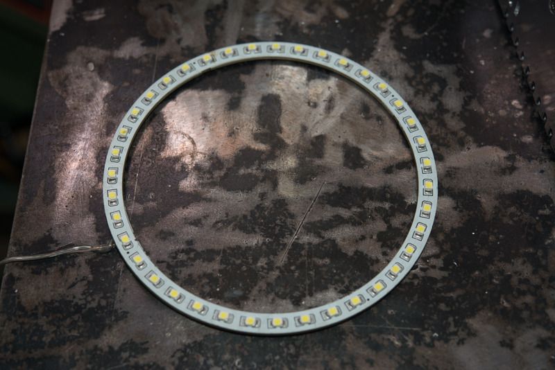
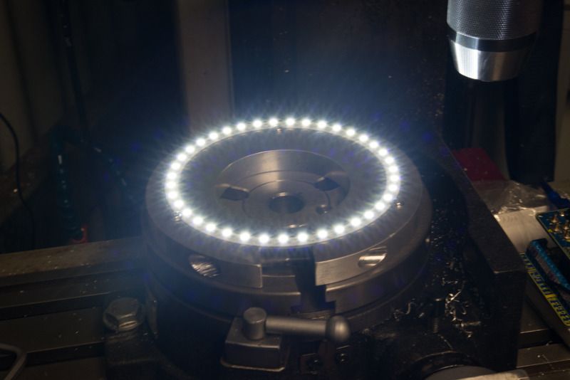
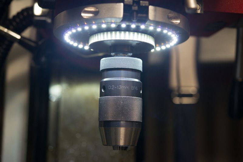
Well I finally got around to using the controller for a continuous milling job. A couple of years ago, a forum member gave me an angel eye light to go round the mill spindle.

DSC_5309_zpsat1kzlwt.jpg


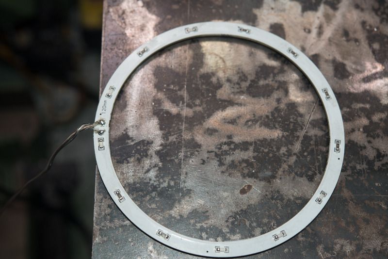
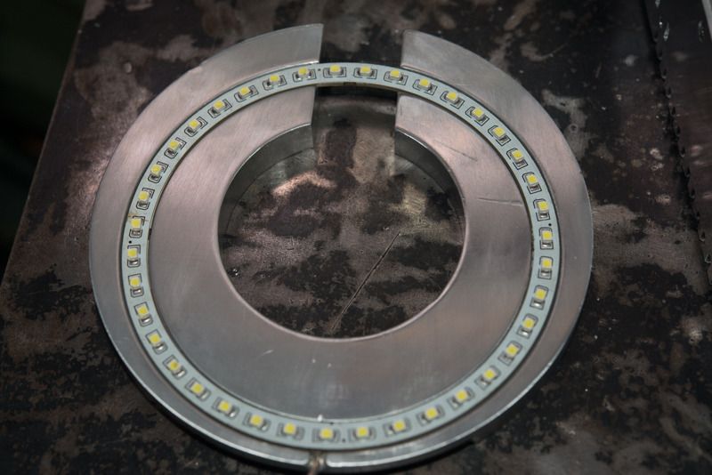
But it has exposed soldered lugs on the back of the board that could short out.

DSC_5310_zps25jdplsm.jpg


So it needs a rebate so it won't short out on the mounting plate.

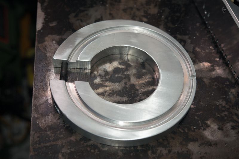
I made this up on the weekend.

DSC_5306_zpsm6yhnjmu.jpg


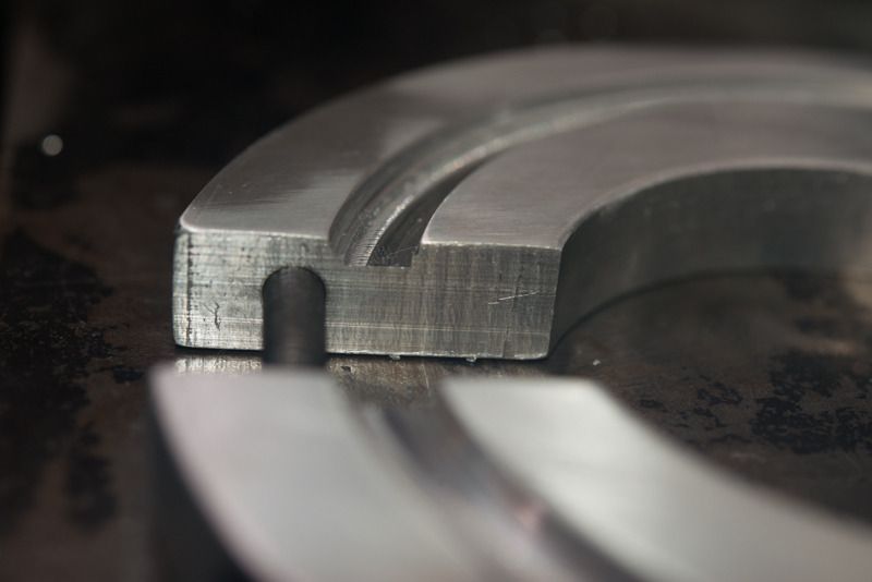
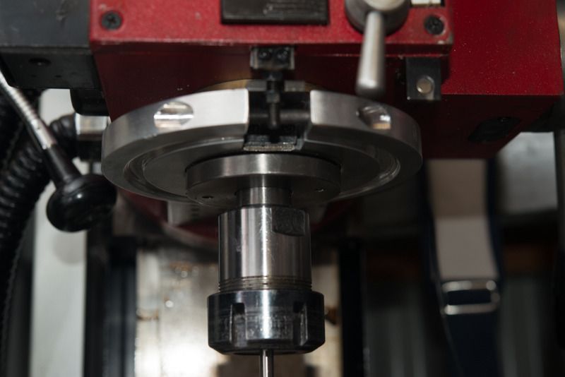
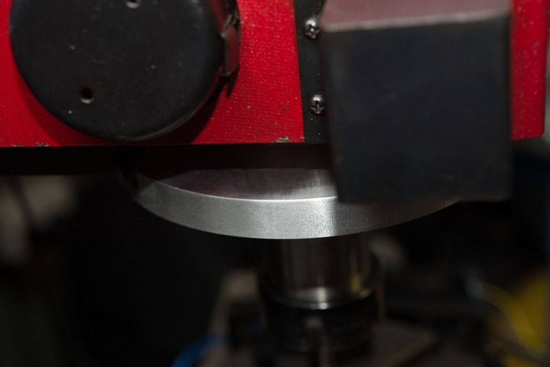
I used the 4 jaw chuck to bore the hole for the spindle in the centre and offset it by 5mm before cutting the groove. I did thios to make room for the clamping bolt. I could not cut the rebate to gain the clearance I needed with the lathe tooling I had so I set it up on the rotary table. Don't ask me how long it took to centre the job on the lopsided hole. A 4mm end mill did the trick nicely to widen the hole on the outside that I could not get to on the lathe.

DSC_5307_zpsnfsuscrc.jpg


And here's the finished article

DSC_5311_zpsygy6nnhs.jpg

and where it will go

DSC_5312_zpsjc6k2sut.jpg


As an added bonus, I'm going to machine a flat on the side so I can mount up a depth gauge for the mill.

DSC_5314_zpsq6yg3zct.jpg


Now if only my 25 year old TC201 Weller Soldering Iron hadn't have decided to die during the week now I'm almost ready to solder up a control board.....
 
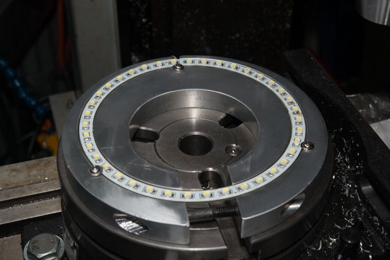
And here was I thinking I'd glue the light in with silicone but then realised it would be much easier to service if I secured the light with screws. So I set the mounting plate up on the rotary table again and set it for 3 divisions and added some M3 flanged screws out of my PC spares drawer.

DSC_5317_zpsasgztf8t.jpg


THe rear screw is mounted on the inside as the power lead exits on the outside.
DSC_5320_zpsskq1a2ua.jpg


Way off topic I know, but this light is just awesome!

DSC_5325_zpsydugi2lx.jpg


Absolutely no shadows anywhere. The 120 mm angel eyes lights are about $7.50 a pair on ebay ex China so I will have spares available.
 
It isn't off topic and frankly the older I get the more important good lighting is. The real question is where does one buy such ring lights.
 
I finally got a bit of time tonight to play with some code again. Pretty sure I've got the LCD class extended to type in a number to 3 decimal places. eg 9.999.

I figured the number could represent millimetres (to 0.001) or inches (to 1 thou or 0.001")
This is an important step for a linear device so you can enter the distance per revolution so it needed to be done before I could add this functonality. I'm actually cheating a bit because while the display shows decimal numbers internally, the number is a long representing the smallest unit of measurement (microns in metric or thou in imperial). eg 0.001 is actually 1 in the code. It would not be too hard to add an extra decimal place. If you imperial guys thought it was necessary, let me know in this thread.

Quite excited to see TorontoBuilder has got his controller boards back.
 
Can't wait, Rod. The biggest drawback to Chuck F's original configuration is that I can't enter # of divisions directly. I have successfully cut a set of 46 tooth change gears with my setup of Chuck F's version, but experienced difficulties when cutting a pair of 64 tooth gears. My Sainsmart LCD-Keypad shield started having button issues. Entering the # of divisions, and stepping for the next cut had numerous button errors or failed responses. At one point, the Arduino actually changed # of divisions spontaneously, and I ended up messing up the 64 tooth gears, on the last cut, of course.
Part of the problem may have been the 9v battery I was using to power the Arduino, it died enough that the display was not readable for the last few cuts. I think the wear and tear on the buttons entering the # of div by repeatedly pressing a button will make for a short life for the shield. I don't know if contact cleaner will help the button issue. I plan to reload the Arduino and try a single 52 or 54tooth gear today.

Chuck
I do have a 5 button module coming on the slow boat...


Chuck, try and use a 12 volt plugpack supply for your Arduino. Its possible that it can't provide enough current to drive the LCD, keyboard and stepper. I don't know if others have used your stepper driver, it may use more power. I also replied on your other thread.

Rod, are you adding a matrix keypad to this project?

Chuck

No. Have to leave something for you guys to do! Someone else thought a rotary encoder would be good to use so where does it stop?

I've bought 5 bigger buttons (1 red for select and 4 black ones) and a hand full of resistors and was going to hardwire it into a case and rebuild to the Freetronics keyboard circuit diagram. I thought that would be more robust in a shop environment.

I'm holding off on putting it in the case. I've got a 48 v power supply to drive my stepper and have a couple of step down power supplies coming on the slow boat (10 amp 48-12v for arduino and spindle light and 5 amp 48-24v for an electric clutch on my X axis power feed.) The idea is that turning off the clutch will completely disengage the power feed to revert to the mill's hand control. The power supply is pretty big so I think I'll mount it on the mill somewhere and maybe have a smaller LCD display and button box.

I decided to get the spindle light fitted up so it could be part of the project.
 
Back
Top