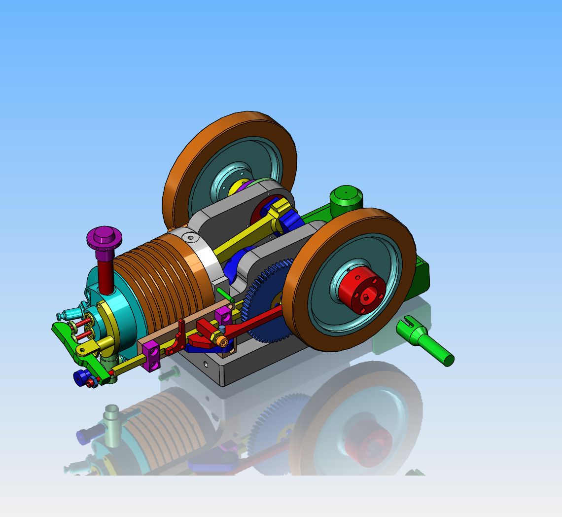
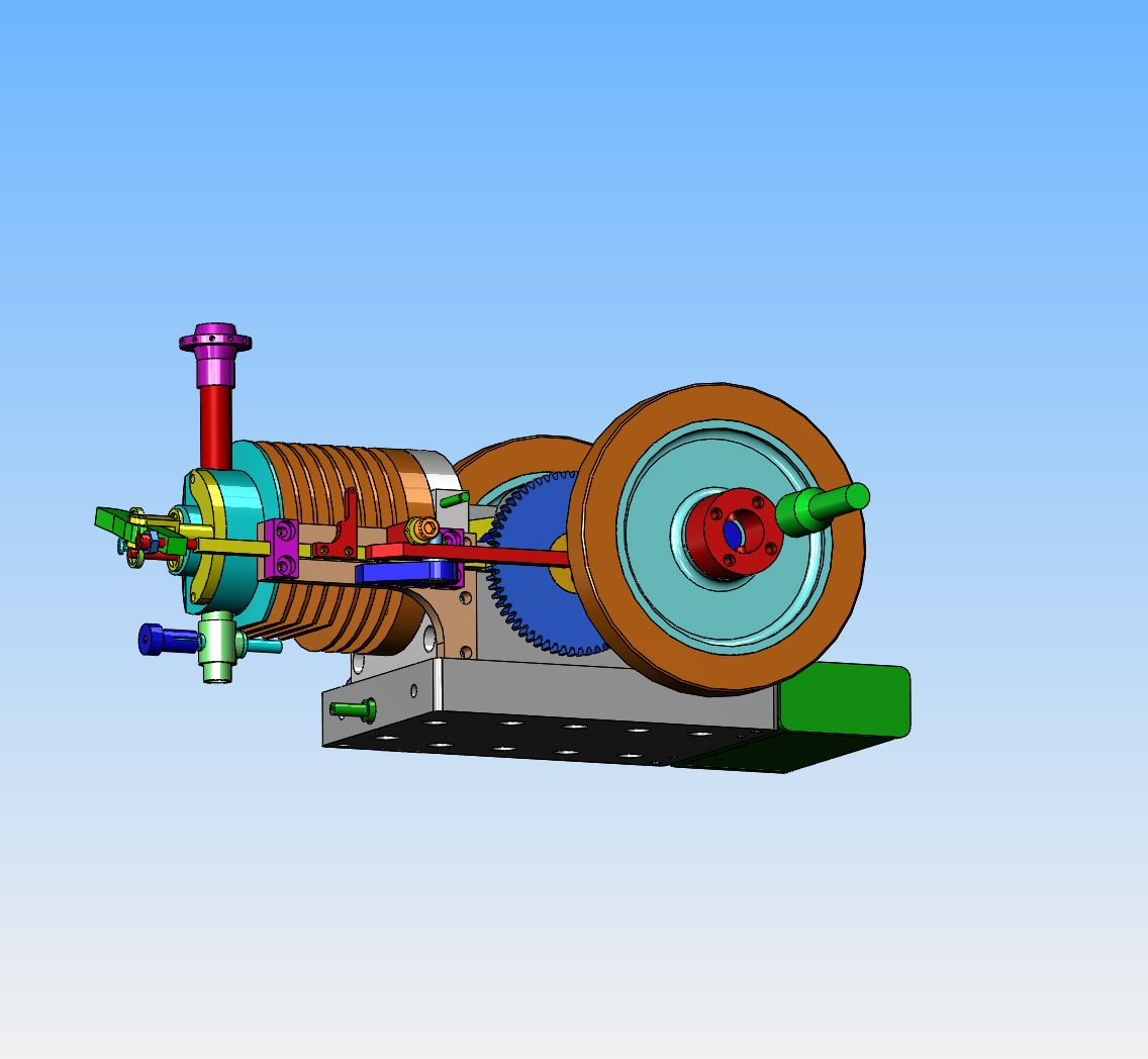
Time for a new Horizontal Hit and Miss engine

Home Model Engine Machinist Forum

Help Support Home Model Engine Machinist Forum:

This site may earn a commission from merchant affiliate links, including eBay, Amazon, and others.
Sory Brian, I am using "Engineering English" again. I don't mean to confuse.
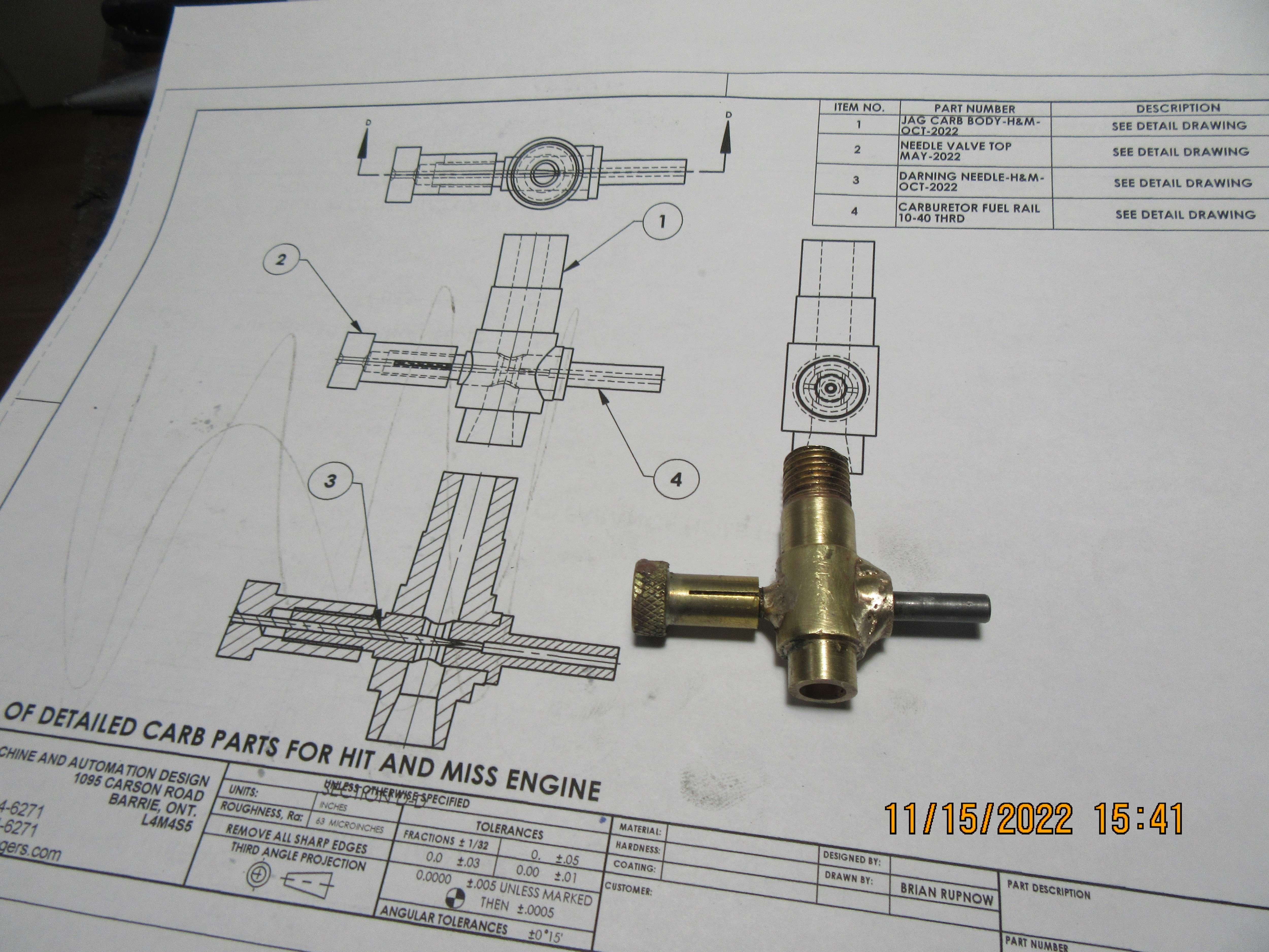
In my "Engineering English" the "Choke" is not a device used for cold starting - as named on cars, but any reduction of cross-sectional area in the passage through which the gas (Air, then air plus fuel) is passing. The Chioke of a carburettor is the reduced diameter zone at or near the fuel jet. As you start with a tapered inlet, the inlet tube itself is "choked" and accelerates the air with consequential pressure drop. Usually this is a simple parallel passage, all-be-it on some race carburettors they add a Bell-mouth which adds to the intake velocity a little, but the main reason is producing laminar flow through the carburettor to maximise gas flow and also velocity. Your carb looks like there is a small step between the passage in the light green part and the blue cross part. This "step" change of diameter will cause a turbulence, which will significantly reduce flow of air (maybe by 10%?) and consequently, slow the air so there is a reduced pressure drop compared with what you could achieve if this was either straight at the same diameter or blended with a further taper in the blue part between the outside and the point where the jet is positioned. Then you will have a better venturi. I am ot saying you won't make your design work as it is, buit simply suggesting an engineering reason for adding a taper in the blue part.
Regards,
K2
 
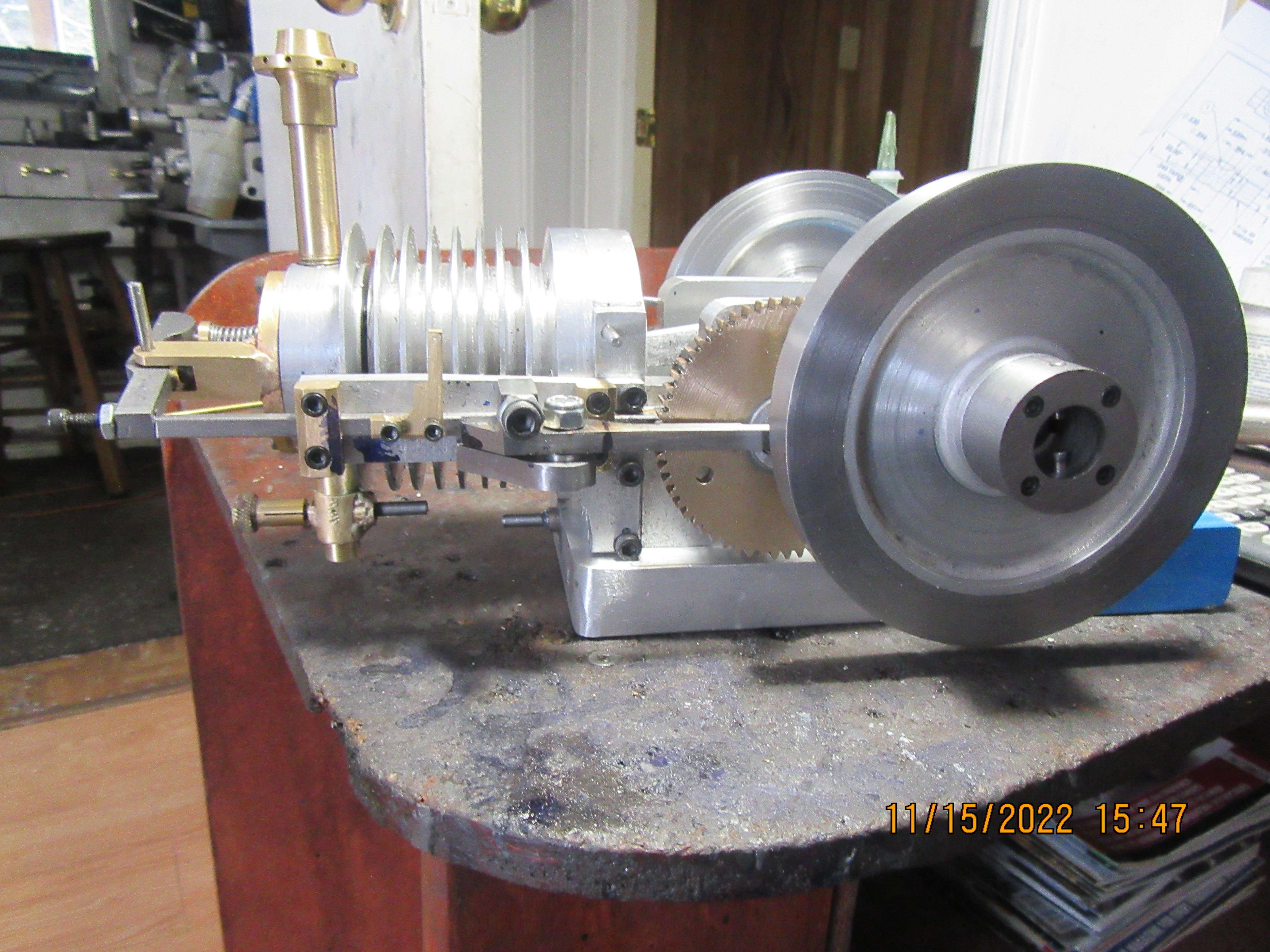
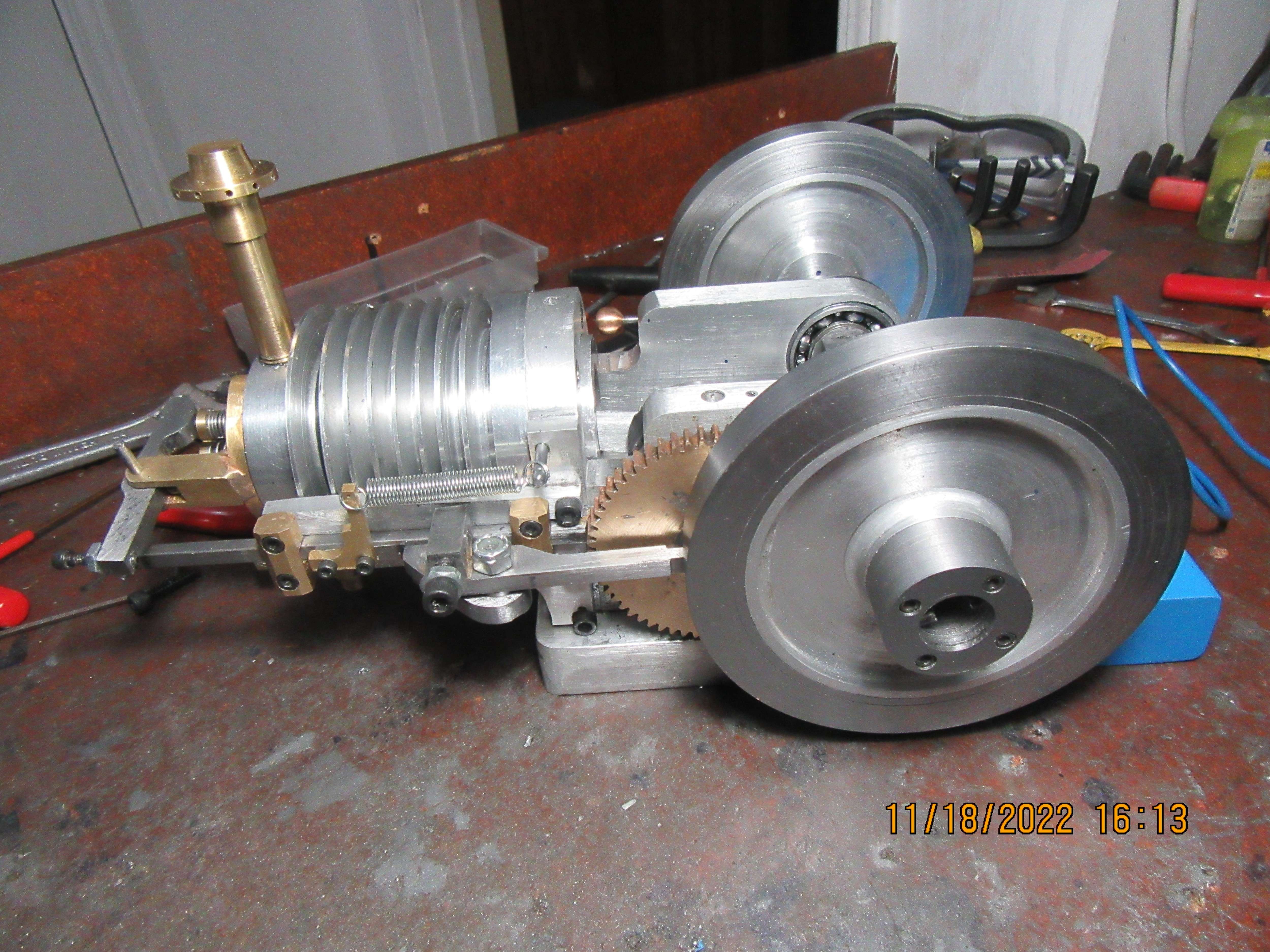
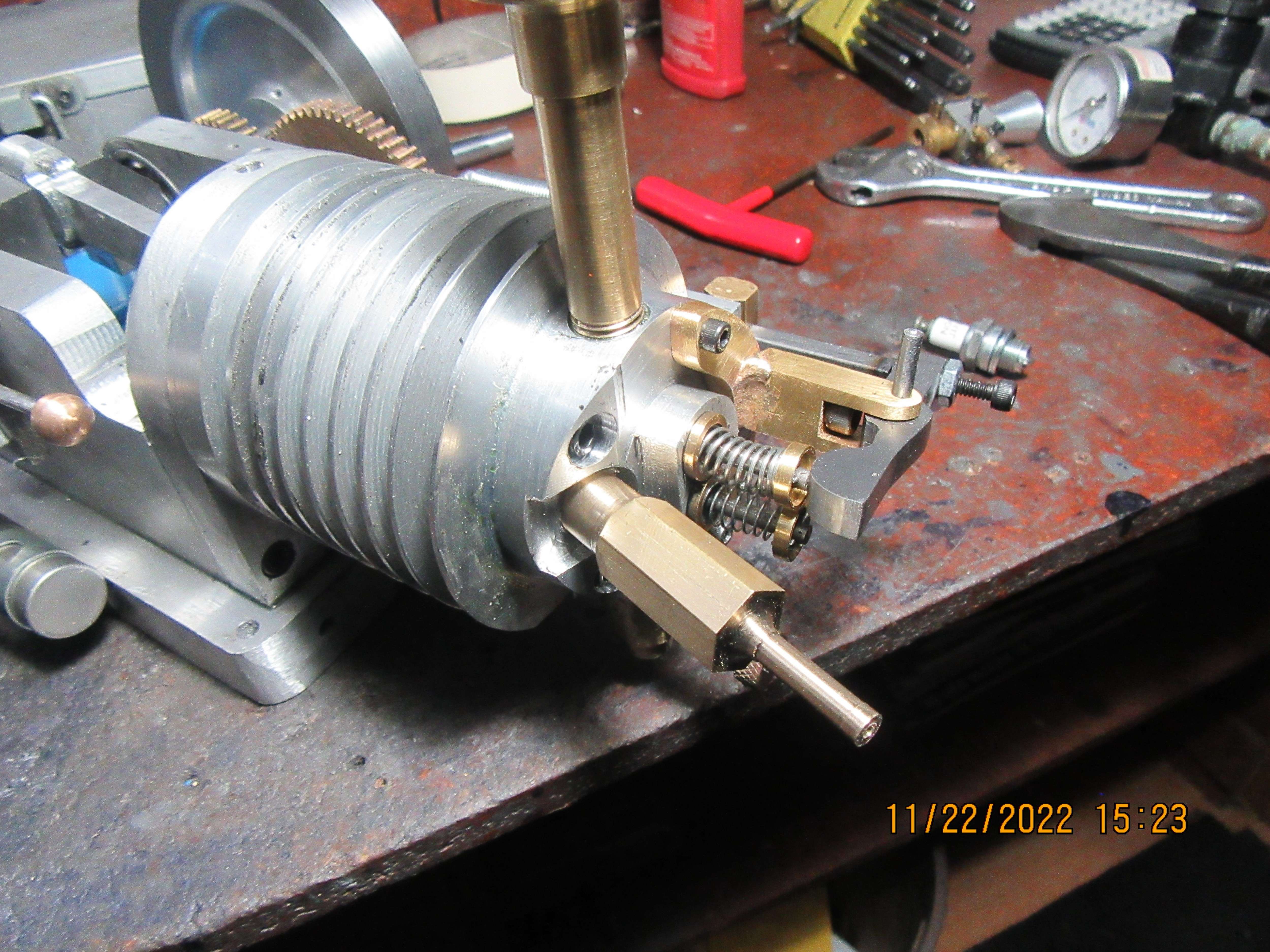
And here we have it, carburetor finished. The soldered joints look a bit lumpy, but when this thing is in place under the cylinder, nobody is going to see it anyways. Steamchick---Most hit and miss carburetors don't have a tapered throat at all---they are just a plain bore, straight thru, and depend on the tip of the fuel rail sticking up into the air stream to create enough restriction to cause a venturi effect. If the cone in the intake side of my carburetor causes any problem (and I don't think it will) I'll turn a cone shaped piece of brass with a bore same as the main carburetor body and Loctite it in place. The carburetor was the last major piece required to finish the engine. Now comes the time for all the farting around required to get the engine running. I have to go down to my local automotive shop tomorrow and pick up a set of ignition points, a condenser, and a sparkplug.---Wish me luck!!---Brian
De8YMy.jpg

httzqd.jpg
 
Thanks Brian. Good luck with getting it running when you have added the ignition bits. I think your design of hit-and-miss governor is simple and interesting. Looking forward to seeing it work!
K2
 
Tomorrow I am going to cut keyways in the crankshaft. But--This requires a bit of thought. On a normal 4 cycle engine, I would cut a keyway in the small gear to lock it in position on the crankshaft. I could then loosen off the grub screws on the cam gear and turn the gear until it reached the correct position to operate my valve train in proper sequence with the position of the piston. I would loosen off the grub screw in the ignition cam and turn it to a position where the spark came at the right time in relationship to piston position. However, on this engine, the cam gear is "fixed" in position on the shaft, and since the cam is part of the shaft, it too is "fixed" in relationship to the camshaft. This means that I don't want to put a keyway in the small gear on the crankshaft, or I won't be able to set my valve timing. Basically, I want to be able to loosen off the grub screws in the small gear and turn it until the cam gear which it meshes with is in the correct position to set my valve timing. My ignition cam is mounted on the crankshaft and has no keyway in it, so I can still turn the ignition cam freely until it reaches a position where my ignition timing is correct, then tighten the grub screws which lock it to the crankshaft. (This is a waste spark set-up, so the sparkplug fires every time the piston approaches top dead center).
 
I had some doubts on the gripping of a grubscrew for the small gear on the crankshaft without the shaft having a flat area. Never build an engine before, I wanted to maximize the chance of it to run without parts coming loose. So came up with the following:

- Cam fixed to large gear
- Small gear fixed to 1st flywheel
- 1st flywheel adjustable but firmly fixed to crankshaft by tapered bushing.

So valve timing is set by rotating the 1st flywheel over the crankshaft.

- Ignition cam adjustable to crankshaft by grubscrew as this does not take any force.
- 2nd flywheel adjustable but firmly fixed to crankshaft by tapered bushing to set the spokes in the same orientation as the 1st flywheel
 
Can't you just unmesh the gears and move the gear one tooth, should give you increments of a a few degrees which should be good enough. Thats how I usually do it where the cam is integral to the large gear and small gear keyed to crankshaft.
 
Jason--Yes, I probably could.--Didn't think of it. So--what have I been doing? Main ball bearings have been Loctited into cavities in side-plates. New sparkplug has been installed. New ignition points have been installed and timed. Condenser has been bolted to side of baseplate and wired up to ignition points, along with the "feed wire" that takes 12 volts to the ignition points. Head gasket has been made and installed. A bit of clearance machining done to the governor side of the con-rod to make sure it clears the governors under all conditions. A bit of clearance machining to both con-rod and con-rod cap, to allow the con-rod assembly to fit thru the 1" cylinder bore. Valve lash has been adjusted. Keyways have been cut in both ends of crankshaft and keys made to fit. Xander--I don't use the separate tapered hub with my flywheels, just two grub screws at 90 degrees apart, one over the key. The separate tapered hub is a good design, but I find that I don't need it, and it does add quite a bit of machining. I think that all I have to do now is make a set of compression rings for my piston, and machine an oiler for the cylinder. I have an oiler left over from another build, but it looks to small and puny on this engine.
oEOcGh.jpg
 
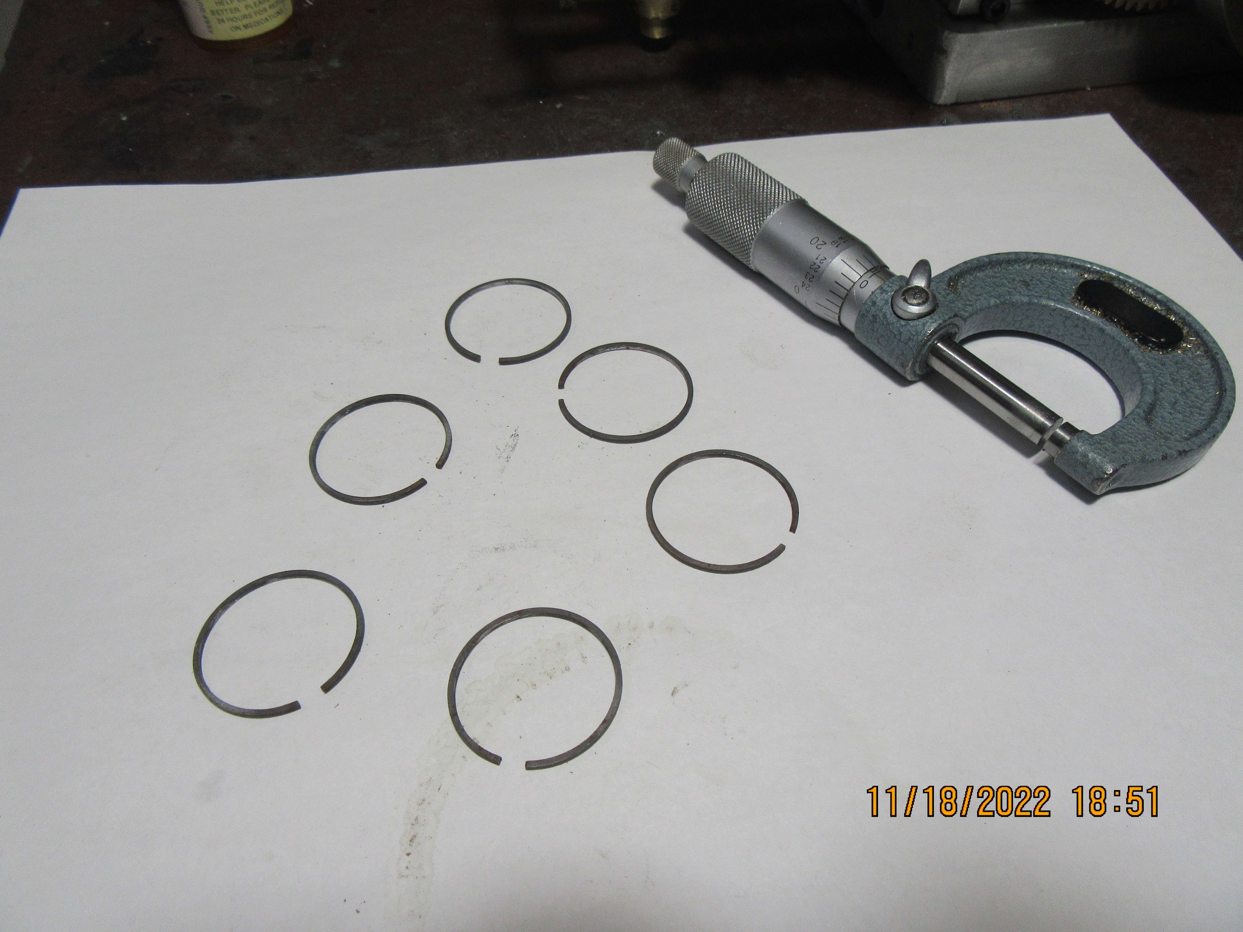
The last time I made piston rings for a 1" piston, I made six extra rings. I have had these rings in a small bottle for the last year or so, and now is the time to bring them out and see what I have. I can see by the gap that these rings have been heat treated, but not "finish sanded". My piston is made, and has ring grooves 0.046" wide. These rings measure 0.045" wide. With a little bit of luck and some very light sanding, two of these rings should do. I have the correct material to make more rings if I have to, but I'm really hoping that two of these rings will do.
haIPMc.jpg
 
Today, for something simple to machine, I'm making the starter spud that lets me use my variable speed drill to start the engine. (That is the green thing floating in space just outside of the flywheel).
KnGEye.jpg
 
Today, the six piston rings were sanded flat, against a piece of 600 grit carborundum paper, backed up by a sheet of glass to ensure absolute flatness. I have a tapered flap sander that fits in my mill that is 7/8" diameter on the narrow end and 1 1/8" diameter on the large end. Each side of each ring was held in my fingers and forced up onto the revolving mandrel to remove any burrs from the inside. Each ring was pushed squarely into a 1" bore spare cylinder that I have, and the end gap was checked with a 0.004" feeler gauge. One ring didn't survive. When I tried to file a bit more end gap into it, it went all egg shaped so I threw it out. Two of the rings were installed in the ring grooves in my piston, and the piston was reinserted into the cylinder with the help of a tapered sleeve that I have which is 1" bore on one end and 1 1/8" bore on the other end. Before I put the cylinder head back on the cylinder, I held the flat of my hand against the cylinder bore and turned the engine over with my other hand, and it did seem to have good suction against the palm of my hand. Everything is finished now, except for the cylinder oiler.--I don't need the cylinder oiler to start and run the engine. If the engine runs well, and if I sell enough plan sets, I may indulge myself and buy an oiler from one of the companies which sell them. Wish me luck people!!---Brian
 
Time for some modifications---I'm not getting a lot of compression, and I should be. I unscrewed the sparkplug and went searching for my air jack that screws into the M10 x 1 pitch threads in the sparkplug hole, so I can put some air pressure into the cylinder and see exactly what is leaking compression.--Ha!!!---Can't find one. Maybe I never had one. So--I ordered an M10 x 1 threading die from Amazon and it is supposed to be here tomorrow. As soon as it arrives, I will make up an air jack to match the sparkplug threads. Secondly, even though the carburetor should be positioned high enough from the fuel tank to prevent fuel syphoning down and dripping out the carb throat, it isn't. Poop!!! Can't have that, don't want to burn the place down. So--shave a flat on the bottom of the cylinder and cylinder head cooling fins and modify the carb body a little bit, and this allows me to lift the carb up 1/4". No way that fuel is going to gravity drain uphill.
IoOpet.jpg
 
Sparky--Best answer is no, I don't. My lathe requires you to change a bunch of gears to cut different threads. I did set up one piece of 3/4" round aluminum, followed all the directions and did cut a quite acceptable thread which accepted a 3/4" off the shelf nut. Having proved that I actually could do that if I really, really had to, I've never tried to cut a thread since.
 
Most lathes also require a special gear in order to cut metric threads. Also cutting a thread on something that small is a lot of work. That is approximately 3/8 dia x 3/8 long.
 
That thread is the thread on an M6 sparkplug from NGK. I wanted a die, so I called my usual tool supplier in Barrie. They could have a die here tomorrow for $37. I said that was too much. He said he would check his other suppliers and find me something cheaper. He called back in 15 minutes and said he could get one for $17.50 but it would take two weeks. I said no, and went to Ebay---they had one for $10 but I couldn't get the damned site to work. Then I went to Amazon, and they had one for $13 and would deliver it here tomorrow. This is for a die that I might use twice a year.
 
Hi Brian, don;t know if you have seen this video but "Blondi Hacks" makes it relative easy. We can't let the fairer *** better us but she is very good and has many sites.
John.
 
I spent this morning preparing a fixture which screws into my engines combustion chamber so that I can pressurize it with air to see where it is leaking compression. My M10 x 1 threading die came this afternoon and I quickly threaded the end of the new fixture and screwed it into the sparkplug hole. I found a thread yesterday on Youtube where a man done this, only he incorporated a Shraeder valve from a car inner tube into the fixture, and then after pressurizing the cylinder he disconnected the air pressure and said that the combustion chamber should remain pressurized for 15 to 20 seconds after the air line is taken away. This sounds like a very good idea to me.
fxRGYV.jpg
 
Attaching a piece of tubing to the fixture and blowing on it by mouth quickly shows that my exhaust valve is not leaking, but my intake valve is. There doesn't seem to be anything leaking past the piston and rings. This stands to reason, as the mechanical exhaust valve has a much stronger spring than the automatic intake valve. I will now pull the cylinder head off and relap the intake valve.
 
Improvement---engine is firing randomly. This is definitely an improvement over not firing at all. Relapping the intake valve has helped a lot with the intake valve, it is sealing much better now. I think the spring on my intake valve is too stiff---Have to root around thru my box of springs and find a lighter one. Moving the carburetor up 1/4" higher has fixed the fuel dripping from the carburetor.
 

Latest posts

Back
Top