Time for a new Horizontal Hit and Miss engine

Home Model Engine Machinist Forum

Help Support Home Model Engine Machinist Forum:

This site may earn a commission from merchant affiliate links, including eBay, Amazon, and others.
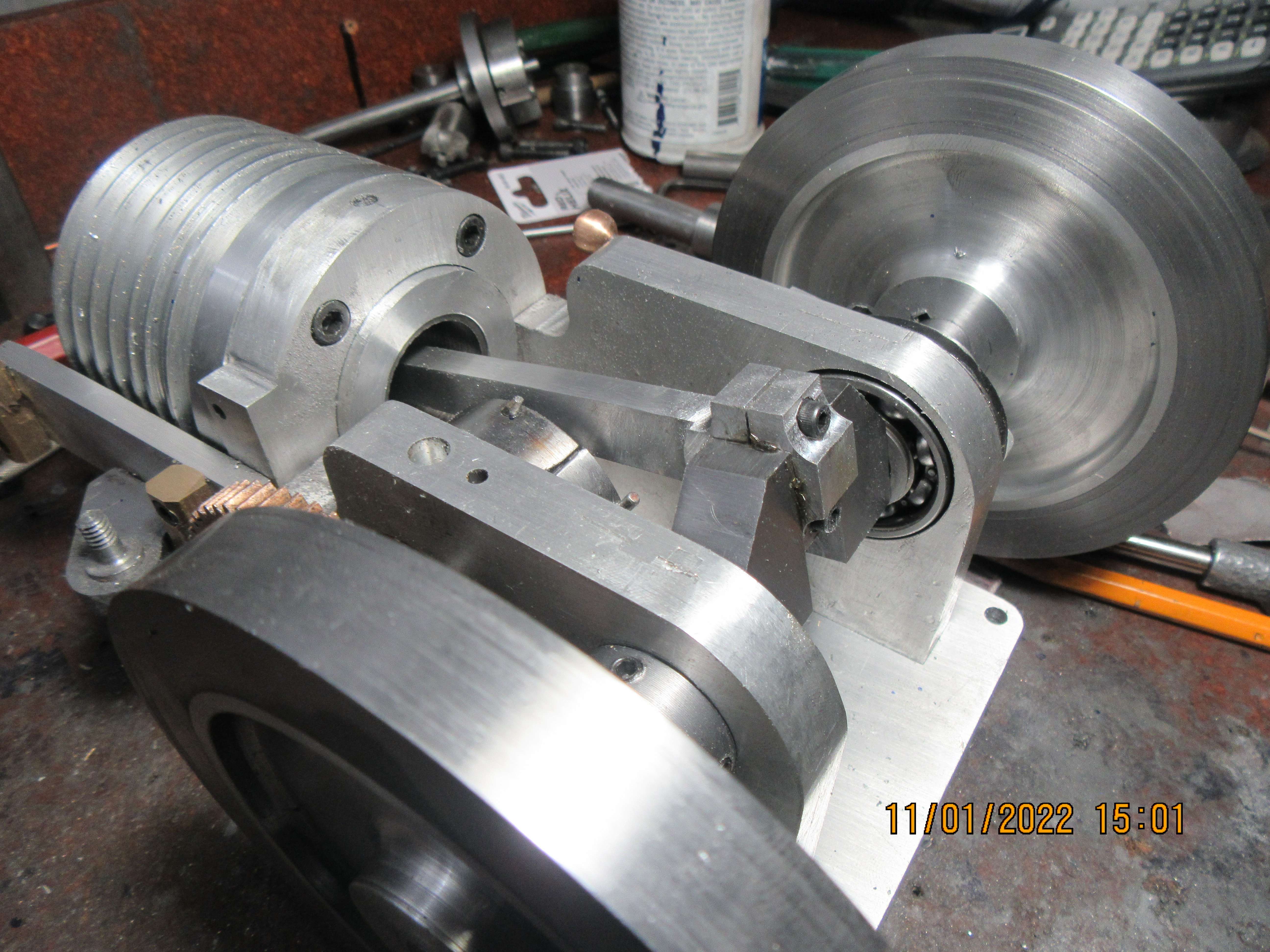
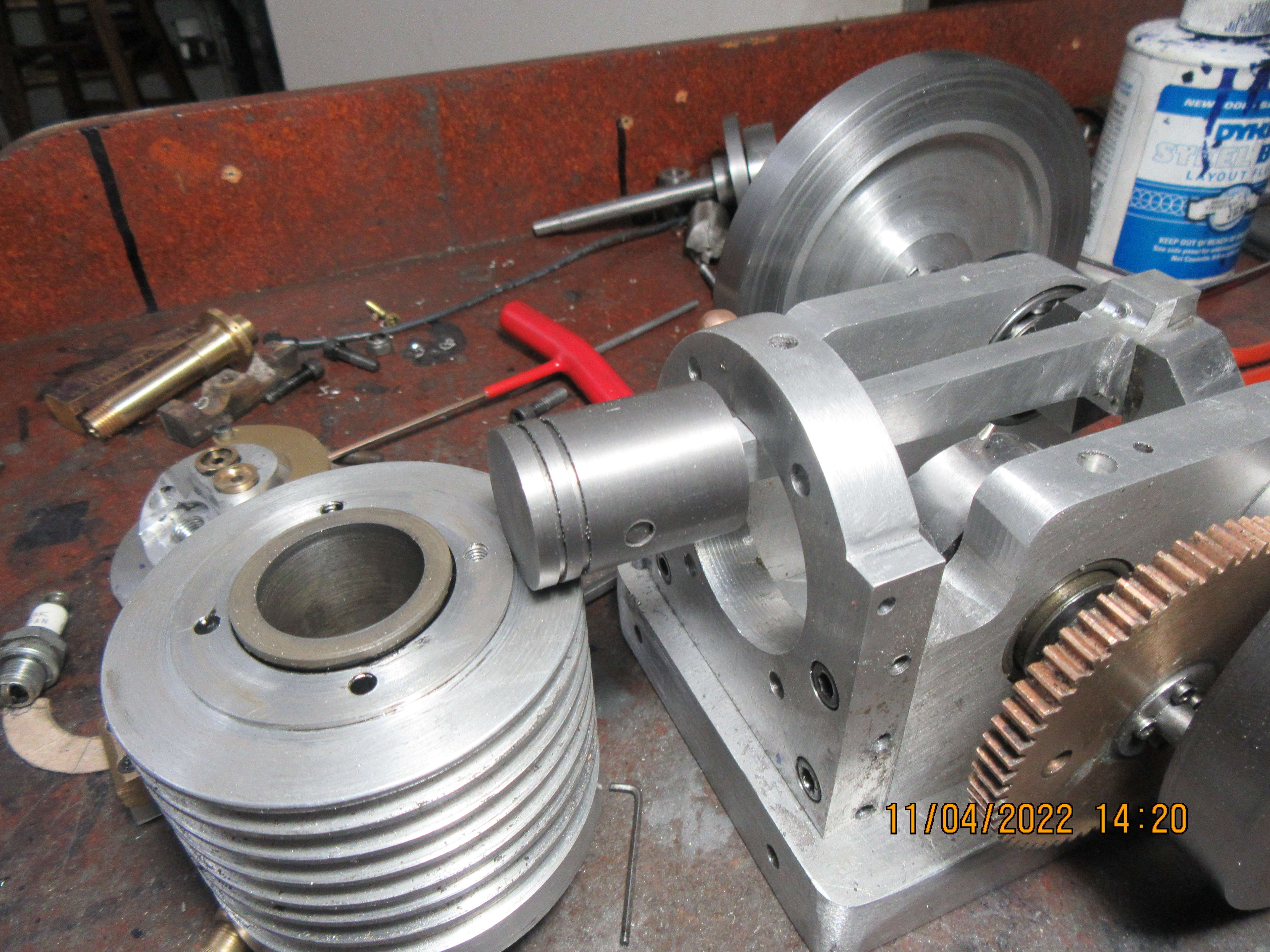
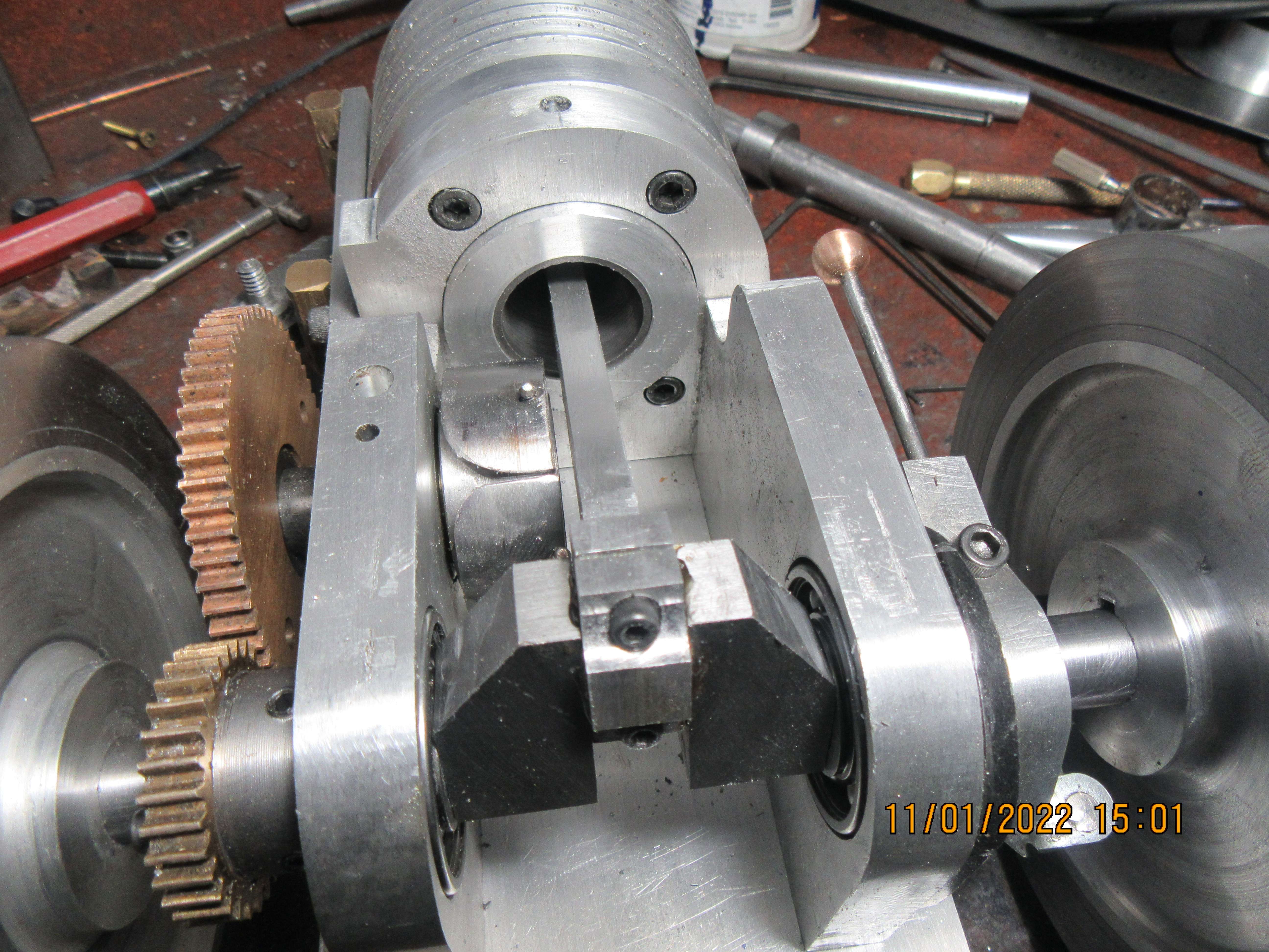
Today's nifty trick was to build and install a connecting rod and cap. It fits, fits very well. Yes, there is room between the governor and the connecting rod, as I thought there would be, but there is not a lot. Ah well, a miss is as good as a mile.
vHYtrF.jpg

LlVqdD.jpg
 
re: #99 - Craig:
ON Differential expansion... This is very complicated for a cast-iron liner in an aluminium block. - Fit and temperature and yield strength all play an "active" part.
I was involved in trying to predict the fit of a steel tube pressed into an aluminium block. The calculations were proven by the real engines on test - and failed exactly as predicted - except for one factor. The steel and aluminium both deformed permanently, so the result was 2 parts that didn't fit at times and leaked. But the result was that fitted "as originally designed" and "glued" with Loctite thread-lock (the adhesive already in use on the production line in that area) produced a sealed fit that never leaked.
The calculations of differential expansion showed less dimensional change than the "interference" value. But what was actually happening was that the steel tube (a relatively low-grade steel) was swaging when press fitted into the aluminium block (at room temperature) so if removed immediately it was smaller than before fitting. And after reducing the temperature of an assembly to -30C (minimum service temperature at which the engine was expected to be started) the aluminium was found to have yielded slightly such that the hole was measurably larger than the original. The conclusion at +120C (max "design service" temperature at that position) was that the steel tube would be loose in the aluminium... - and thus would leak oil - but the Loctite prevented this. It seemed to form a seal at the edges of the metal-to-metal fit - which was wiped "dry" along the contact surface during assembly (So didn't assist the fitting/disassembly force). - The original "fit" dimensions had been based on the steel tube pressed into an iron block. We never actually changed the dimensional fit, just added the Loctite as that made the assembly "work properly".
On Richard's engine I expect the Loctite adhesive to secure the components and being so thin a film (actually just filling the machining grooves, so just a few microns thick!) it won't materially affect the heat flow from cast iron liner to aluminium block.
BRIAN, I would have guessed a regular "Thread-lock" anaerobic adhesive should be adequate for securing the "sliding-fit of liner to block. - But follow Loctite's recommendation as they are the experts. - I would (if it were my engine) fit a tiny pin to ensure the liner does not become free to rotate in the aluminium. - It looks (from photos) as if there is a top flange (held between block and head gasket?) to prevent linear movement of the liner. - Good design.
K2
 
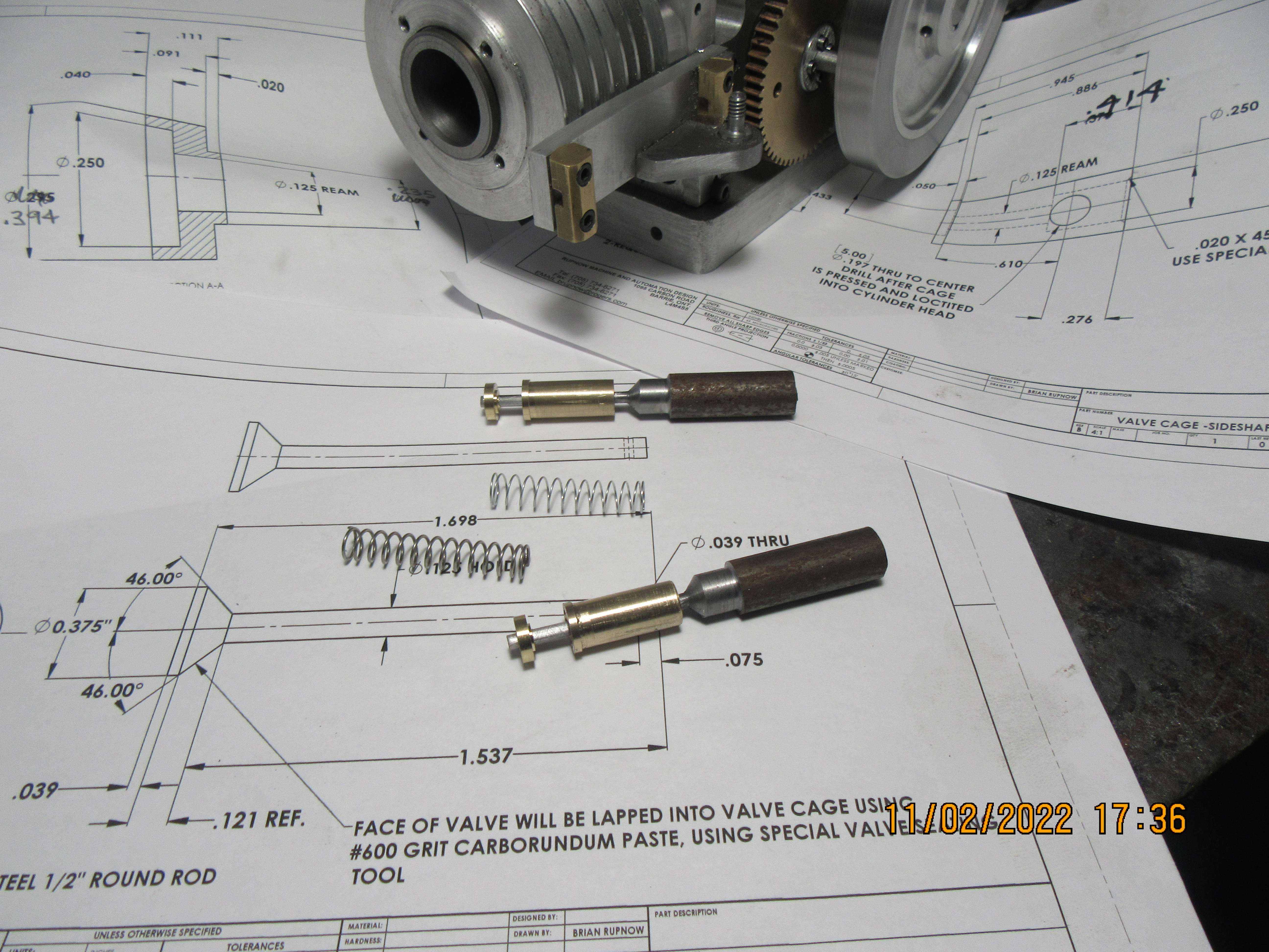
Today was valve train day. We have the valves, turned to a smooth sliding fit into the valve cages, and into the valve spring retainers. The rusty "handles" are still attached to the valves so I will have something to hold onto when I lap the valves into the "seat area" in the valve cages. They will be cut off after the lapping is finished. The springs in the picture will be cut to the correct length and will serve as valve springs. The valve cages will be Loctited into the cylinder head.
Xqebdn.jpg
 
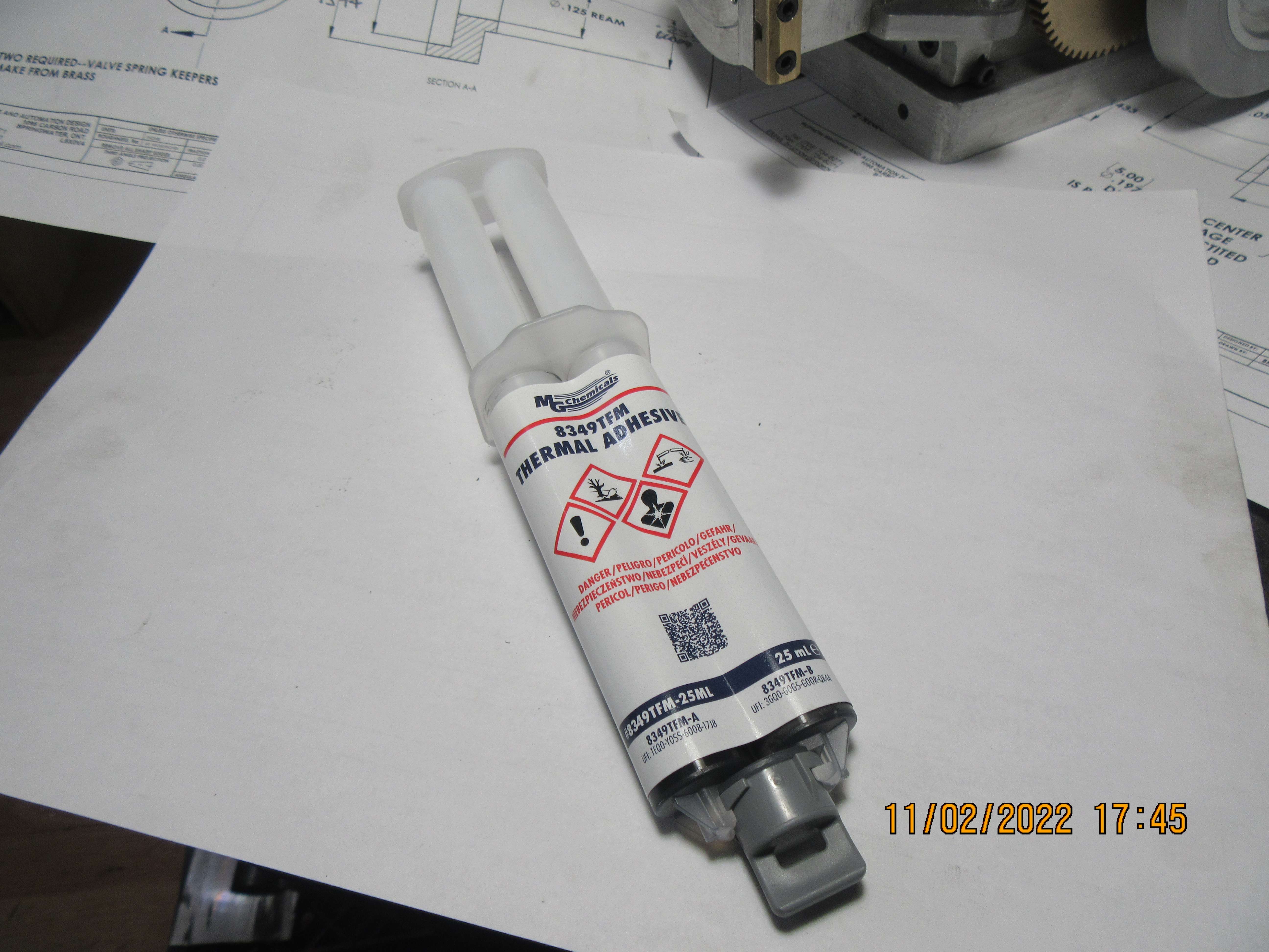
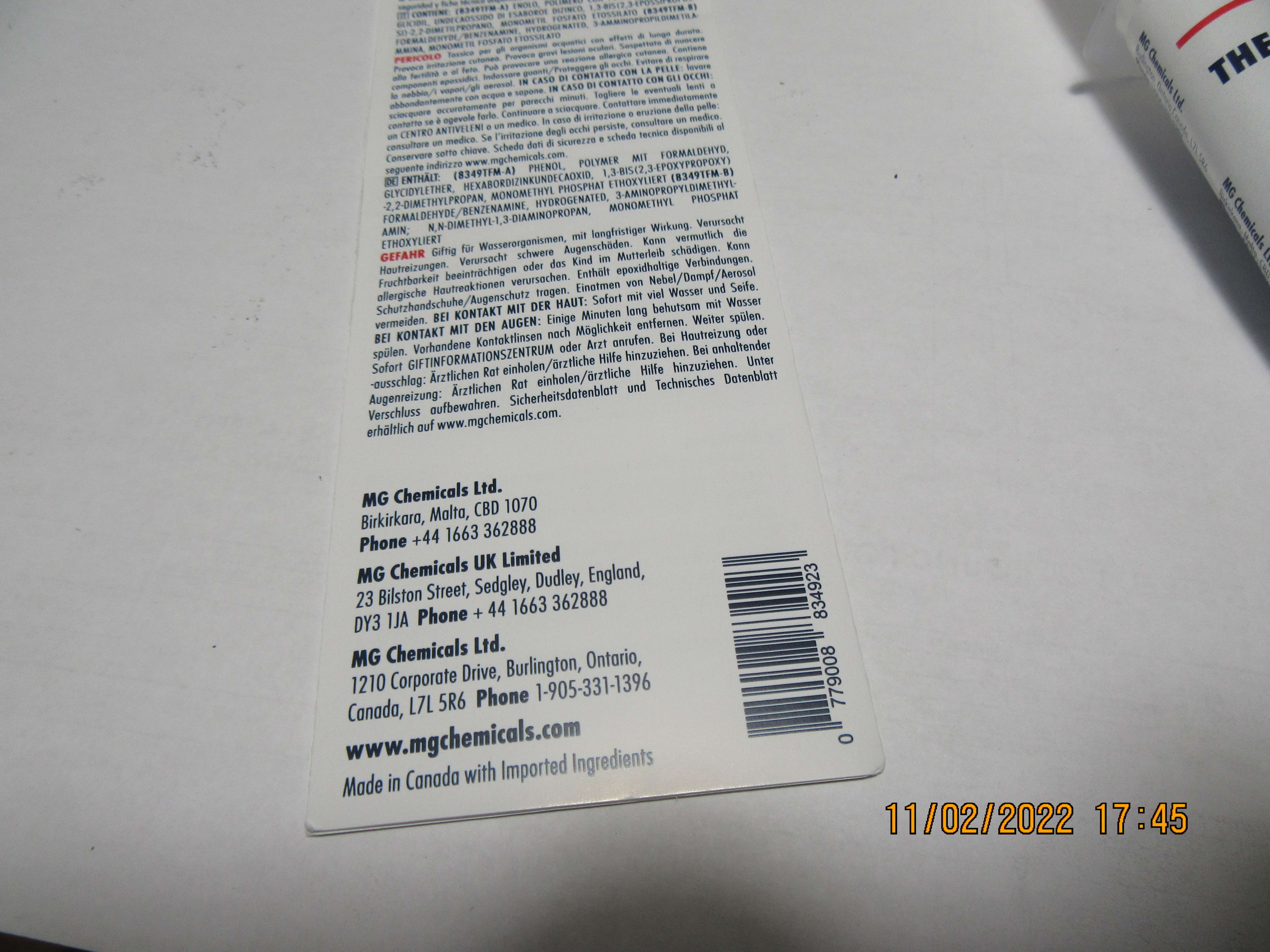
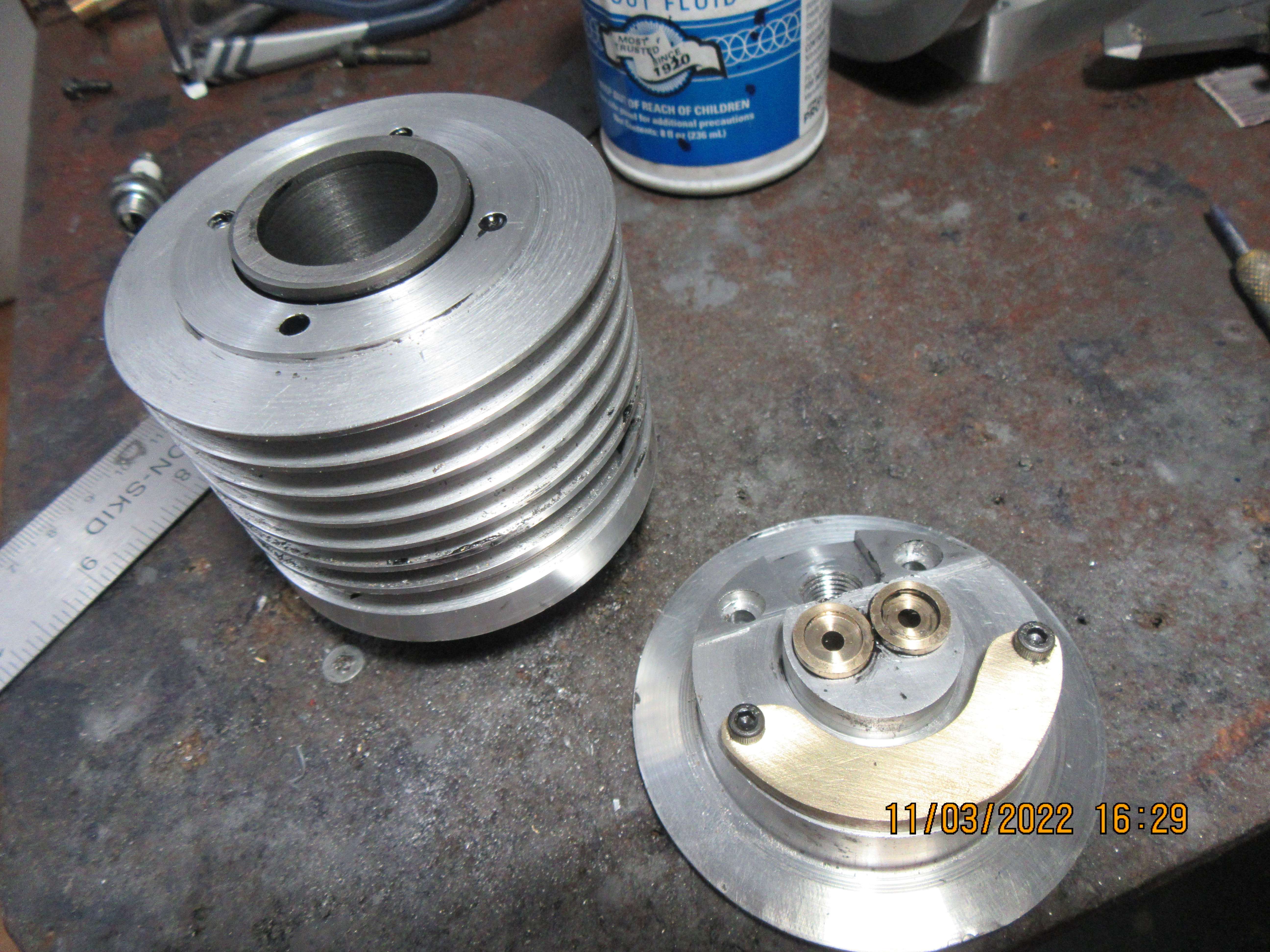
And this is the "fix" for all who may at sometime be "Machining Challenged". My cast iron liner which was supposed to be a medium press fit into the aluminum outer cylinder, ended up being a "smooth sliding fit" into the aluminum outer cylinder. This is not a good thing, because without a press fit, there will be very poor heat transfer from the inner cast iron sleeve to the outer aluminum cylinder which has the cooling fins on it, to radiate heat away. This is a thermal, heat conductive two part epoxy. It's main purpose in life is to transfer heat from one metal surface to another. It cost me $41 Canadian, but it is going to save $15 worth of cast iron and about two hours of my time. I will mix it up, coat my iron inner cylinder liner with it, then slide it into my aluminum outer cylinder and let it set up for 24 hours. I will let you know how it works, I have never used it before.
KqQXq9.jpg

JjNdyd.jpg
 
The rusty "handles"
I always thought that the valves had to be some sort of stainless steel to avoid corrosion and hence leaking valves over time. What is your experience? Would save me buying and machining stainless next time.
 
Last edited:
Today I had a bad case of "lazy arse". I used my thermal epoxy to attach the cast iron cylinder liner into the outer finned aluminum cylinder housing, and while I was doing that I decided to use the same epoxy to fasten my valve cages into the cylinder head. I wasn't going to do anything else today except have a nap, but decided that I had to machine at least one thing to keep the project moving forward. I searched around in my brass bin until I found a piece of 3/16" brass large enough to make the bottom part of my rocker arm pivot from, and that's all I made today.
GhRaYV.jpg
 
Top job Brian. I like the way you consider all the various things that affect the design of parts - such as heat flow, fits, material selection mentioned recently. This reinforces my knowledge and adds where I am less experienced. Keep up the good work. And your patience combined with the ability to resolve odd problems is an example to s all .
Thanks for posting your work - warts n all!
K2
 
Hello Steamchick--Thanks for stopping by and saying Hi. Today I machined a piston from cast iron. First thing I did was to lap the inner cylinder sleeve with a brass lap and 600 grit paste to bring everything to a uniform finish inside the cylinder. Then I turned the piston in the lathe until it was about 0.002" oversize. I then use 220 grit garnet paper to bring the o.d. down just enough to start the piston into the cylinder, then stopped working on the o.d. and completed the rest of the features on the piston. Once I reinstall the cylinder, you won't see anything of this piston, so here's a picture of what it ended up like.
6Fr0qP.jpg
 
Hello Brian. I'm guessing you are partial to cast iron rings, which is great, over the Viton O-rings.
I just have been noticing more and more folks utilizing the Viton option. I'm guessing because it is a lot less fuss.
Thank you and keep up the great work.

Greg Knipp
 
Greg--People use Viton rings because they always work and they are really easy. I have bought a lot of fairly specialized equipment and made quite a number of cast iron rings, and I'm still not good at it. I try, because that's what we all do--try and improve the way we do things. I wish I was more sure of myself when it comes to cast iron rings.
 
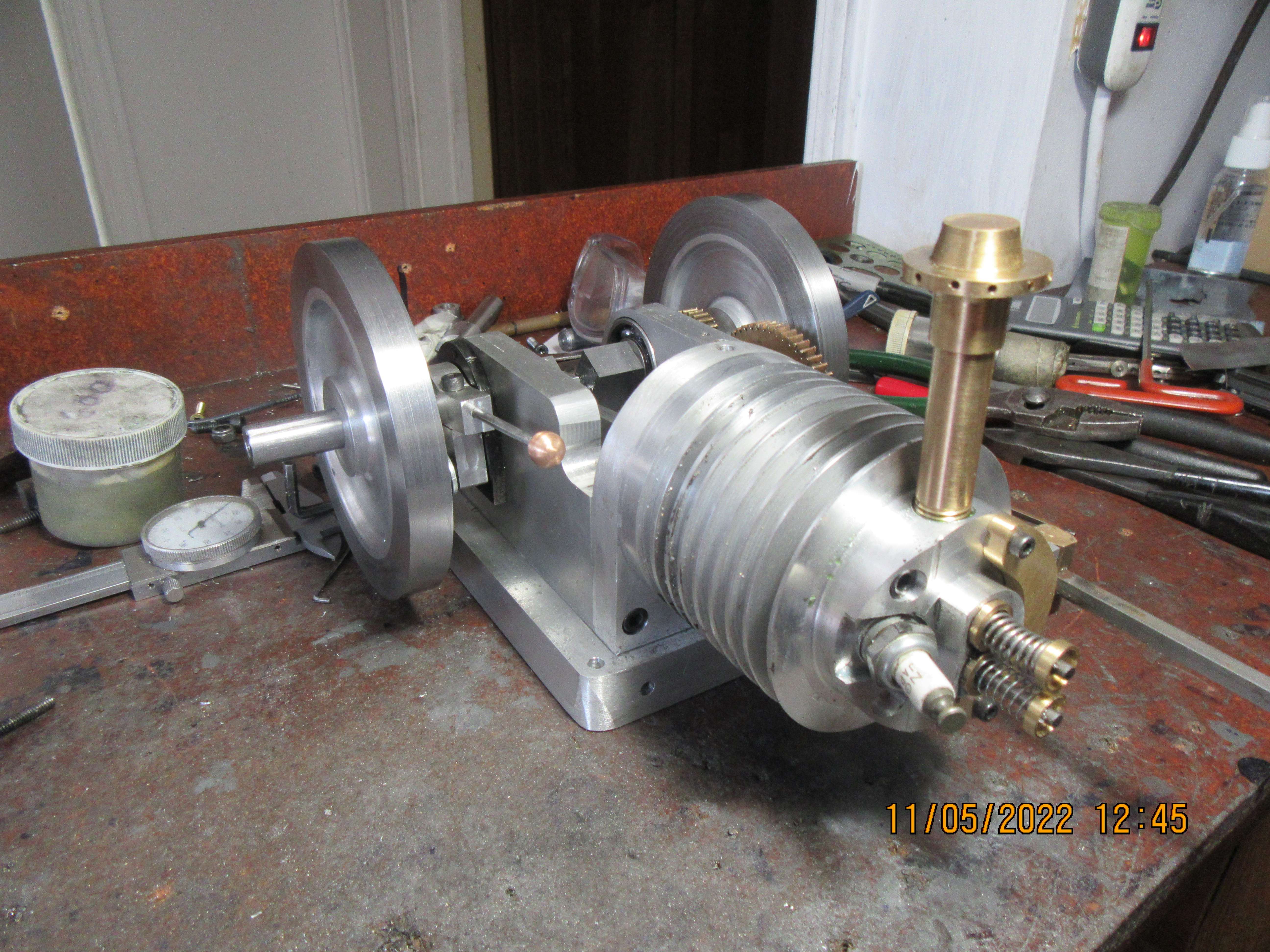
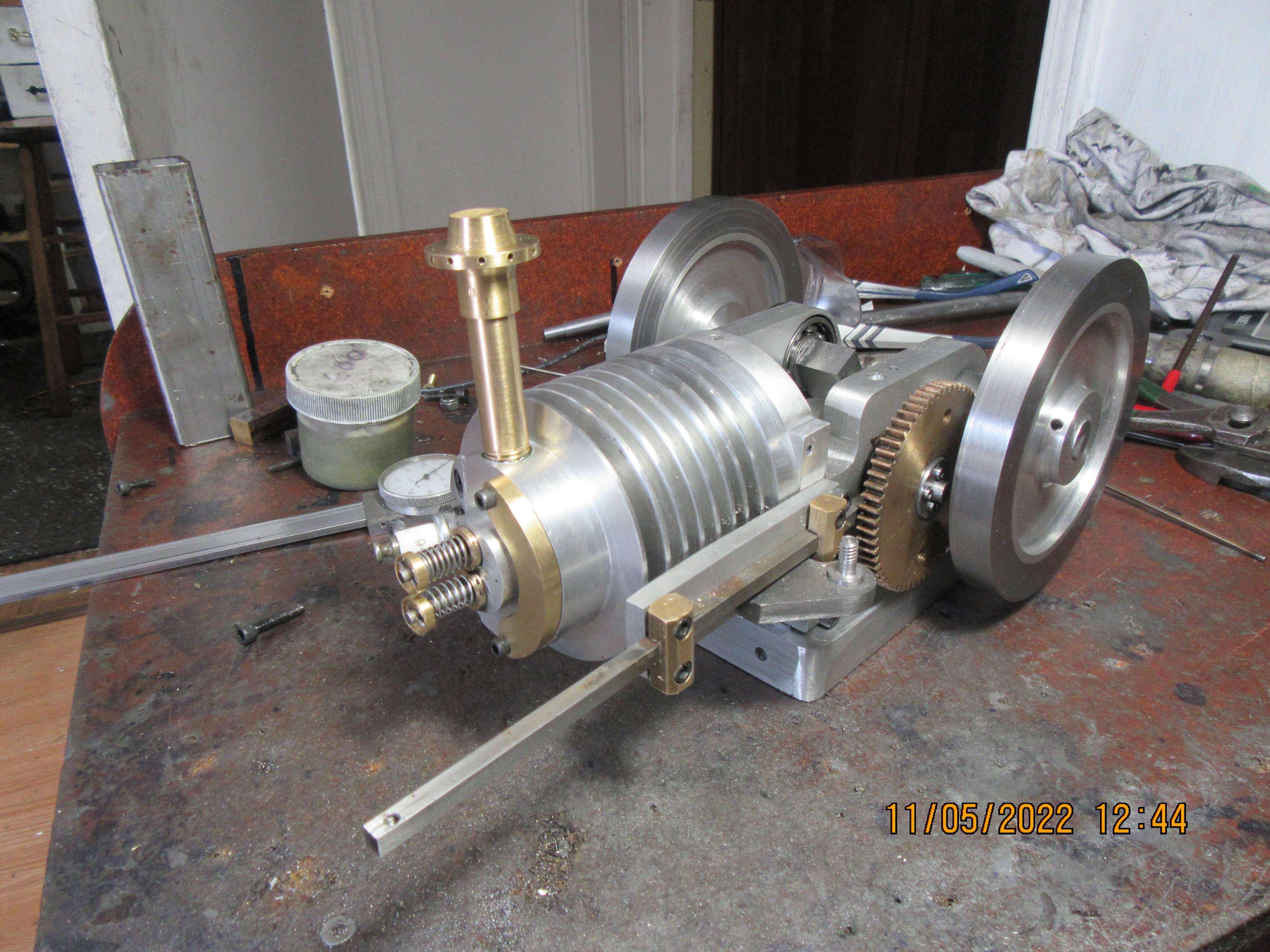
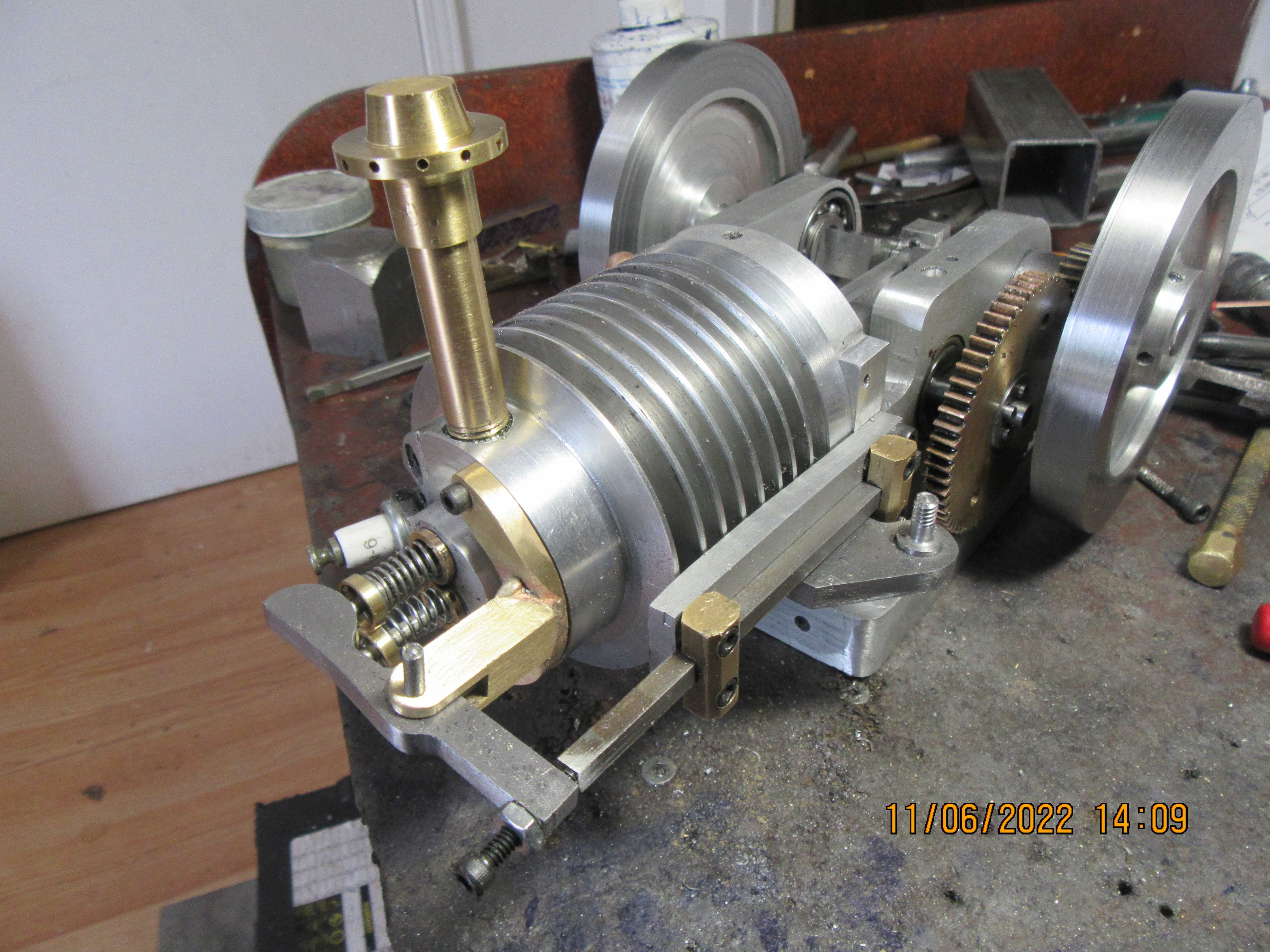
This morning I cross drilled the 0.039" cross hole thru the valve stems for the cross pin that holds the valve springs in place, then lapped the valves into the seats and cut the "handles" off of them. The valve springs were cut to length and installed on the valves. The cylinder head was installed, with the exhaust stack loctited and threaded into it. I found a piece of 3/16" square keystock and mounted it in the guides, as it will be used to ensure that the rocker arm support gets installed in the correct place. Probably the next thing I will make is that rocker arm support tower and the rocker arm itself. The only thing outstanding now are the gas tank, the carburetor (which I will make), and finishing up the hit and miss mechanism.
8Ym7xu.jpg

zMvUhV.jpg
 
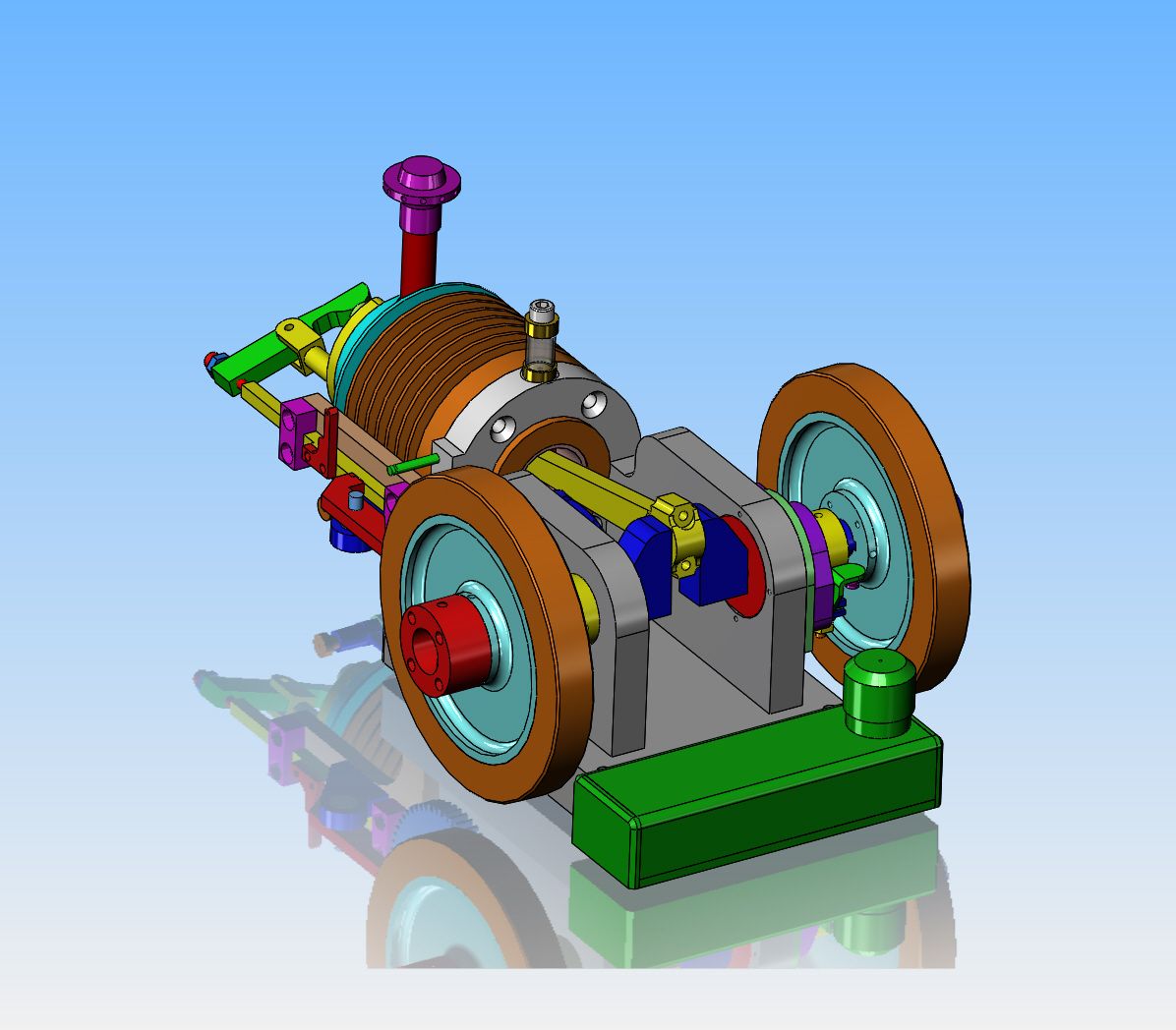
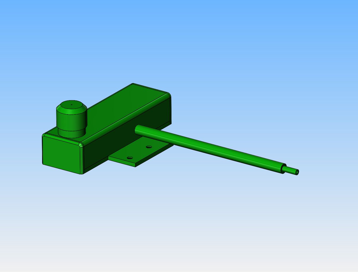
Today I'm working on the rocker arm and support pedestal, but decided to make a couple of design changes on other things. There is simply no good way to mount the gas tank below the cylinder as I had it before. Firstly, it interfered with air circulation around the cooling fins on the cylinder, and secondly, even more important, there was really no good way to hook up the carburetor to the gas tank---they were too close together. My plan now is to mount the tank at the other end of the engine frame, and drill all the way through the engine baseplate to allow a discharge pipe to come out at the carburetor end, making for an easier gas line hook up. I have also taken the radial slots out of the flywheels. They do nothing except provide an interesting visual as they rotate, but add nothing in terms of performance to the engine.
3rtbIh.jpg
 
The rocker arm and rocker arm support tower are finished. A couple of minor things yet to be done, but not today. I think I will build the gas tank tomorrow, just to get it finished and off my list.
FZ1RPJ.jpg
 
Today I am going to build this long peckerd gas tank. I have a piece of 1 1/2" sq. tube with 1/16" wall, and hopefully can come up with enough scraps of 1/8" plate to build it without buying anything.---An interesting side note---The last time I used my relatively new tig welder, it was just horrible. Kept arcing like crazy, burning off the electrode, terrible results. I switched over to the mig welder and accomplished what I had set out to do. Last night, as I was laying in bed, going over my days work, I had a sudden thought. --The last time I used that tig set up was to weld aluminum, and I never changed to a proper steel welding electrode afterwards. I'm hoping that today, with the correct electrode in the tig, I get better results.---Brian
9h2i0e.jpg
 

Latest posts

Back
Top