The best angle of camshaft

Home Model Engine Machinist Forum

Help Support Home Model Engine Machinist Forum:

This site may earn a commission from merchant affiliate links, including eBay, Amazon, and others.

sition

Well-Known Member
Joined
Jun 11, 2018
Messages
60
Reaction score
1
hello everyone! I just want to make a four stroke engine recently. I would like to ask you about the angle between the camshaft. 1. The high angle cam in the automobile engine is 270 degrees. Is the included angle 90 degrees? I bought a toyan engine and their camshaft angle seems to be 90 degrees. 2. Which angle is more suitable for low speed or can make the engine run as low as possible. Thank you very much for your reply!
 
Yes, I realized my nonsense. so sorry!!

My goal is to build an engine that can jog when idling.

After reading a lot of discussions in the forum, I summarized three points.

1. The air intake shall be at an angle of 220

2. Low compression ratio or (low cylinder pressure?)

3. Huge flywheel

The technology I'm looking for is to achieve idle speed between 800-1200 without relying on too large flywheel.

Too big a flywheel makes the engine look unreal

May I ask you?
 
There's just too many variables to give you any kind of answer. Bore, stroke, compression ratio, overhead valves, L head. You'll have to be a lot more specific with your information to get a reasonable answer.
gbritnell
 
Here is the true story of the cam and valve timing that I use for all of my gasoline engines. This cam is longer than the most cams are, but the profile is exactly the same. I use the same profile for both intake and exhaust valves. I use this profile for flathead, T-head, overhead valve and overhead cam engines. It works fine for all of them. You can see on the drawing that only 120 degrees of this cam has any effect on the lifter or pushrod. Since there is a 2:1 ratio between the camshaft and crankshaft, that means that this cam actually has 240 degrees of influence on the engine. I set my exhaust valve to begin opening 40 degrees before the piston reaches bottom dead center on the power stroke. Due to the cam profile, the exhaust valve will begin closing 20 degrees after top dead center on the intake stroke. The intake valve begins to open 15 degrees before top dead center on the exhaust stroke, remains open throughout the entire intake stroke, and closes 45 degrees after bottom dead center on the compression stroke. The ignition timing is set to spark 12 degrees before top dead center on the power stroke.
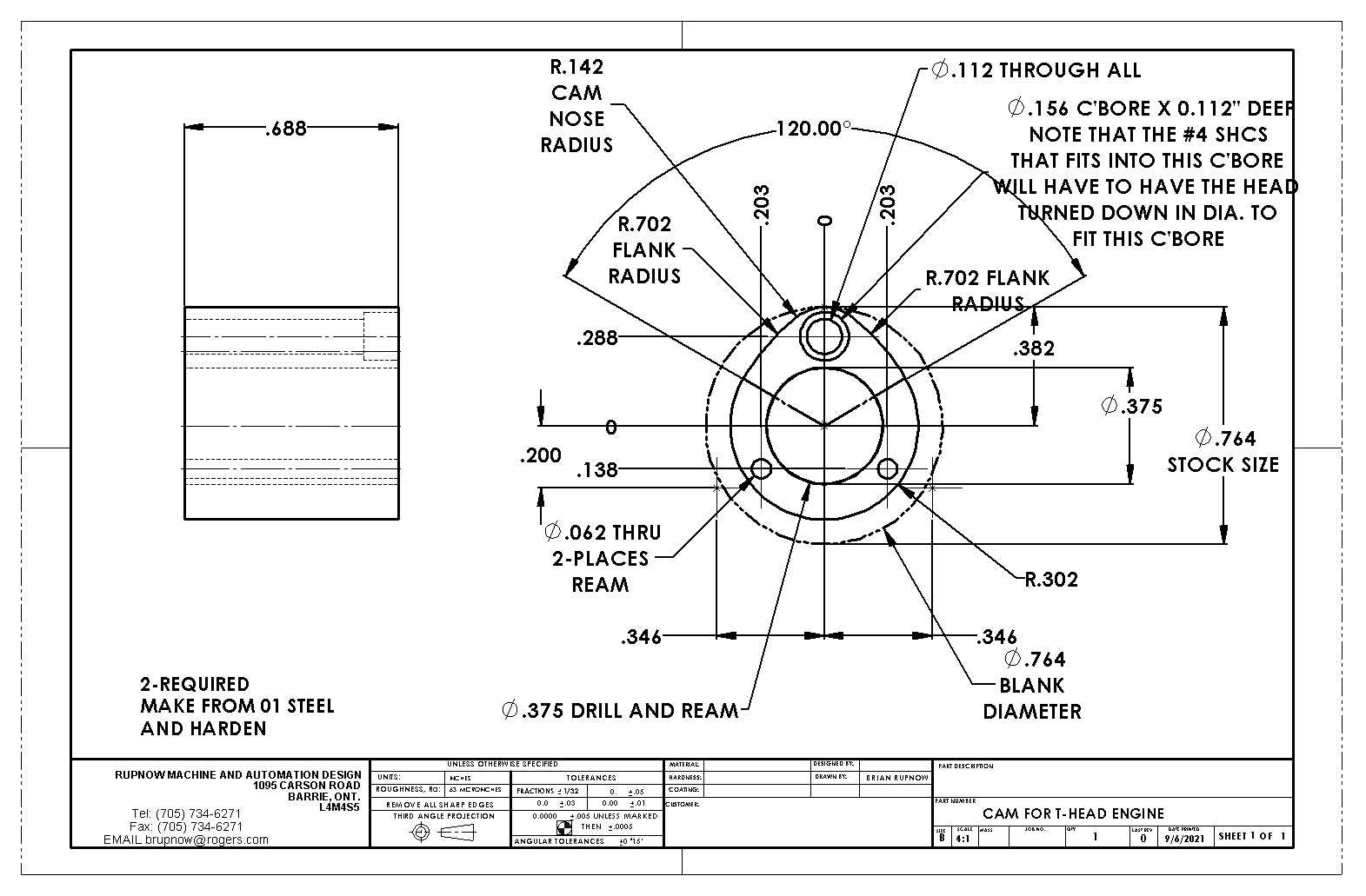
jIrfhJ.jpg
 
Cam design is based on the shape that the cam is operating on the lifter, the amount of rise that is needed at the valve, and the duration of the opening of the valve. A cam with a roller lifter is going to have a different shape that the cam with a flat solid lifter. You need to figure out what your valve motion profile is and then work that back to your cam. I had a program, years ago, that I worked out from an engineering technology manual, wish I could find that book again, and was able to describe the motion I wanted in terms of the final motion of the valve as compred the the crank angle and produce a table of points that I was then able to use to calculate the points for a CNC mill. Anyone have access to a good engineering technology handbook? It could also be done in CAD, the process is rather monotenous as it calls for rotating rour cam 1 degree and then getting all the other components in the correct place and then plotting the interface between the cam and the lifter, wash rinse and repeat, over and over....
 
As a general rule, engines designed for low rpm have less valve overlap than those designed for higher rpm.
Overlap is the angle through which the crank rotates while both valves are open.
With any decent cad system, it is possible to link the rotation of parts (e.g. crank and cam) so that rotating one causes the other to rotate, just as they do with gears.

Pete.
 
Cam Lift Calculator

The above site has a calculator for uniform velocity cam. In general, the cam design is part art and part science. I say part art because I have seen engine cams modified to keep the valves open longer for racing. These engines do not normally idle well. Engine design normally establishes the parameters to achieve as low a vibration and wear as possible. The rpm minimum will also be a function of carburetion and ignition timing. It will do no good to worry about the cam and flywheel if the carburetor can not deliver the the proper fuel at idle. The science is in the math and steel used to make the cam. There are several books on cam design. But it gets down to what do you want that engine to do and what choices you make in the design process.
 
There's just too many variables to give you any kind of answer. Bore, stroke, compression ratio, overhead valves, L head. You'll have to be a lot more specific with your information to get a reasonable answer.
gbritnell

I plan that the cylinder diameter is 17, the stroke is 21, and the compression ratio is 9:1. It is OHV structure
 
Here is the true story of the cam and valve timing that I use for all of my gasoline engines. This cam is longer than the most cams are, but the profile is exactly the same. I use the same profile for both intake and exhaust valves. I use this profile for flathead, T-head, overhead valve and overhead cam engines. It works fine for all of them. You can see on the drawing that only 120 degrees of this cam has any effect on the lifter or pushrod. Since there is a 2:1 ratio between the camshaft and crankshaft, that means that this cam actually has 240 degrees of influence on the engine. I set my exhaust valve to begin opening 40 degrees before the piston reaches bottom dead center on the power stroke. Due to the cam profile, the exhaust valve will begin closing 20 degrees after top dead center on the intake stroke. The intake valve begins to open 15 degrees before top dead center on the exhaust stroke, remains open throughout the entire intake stroke, and closes 45 degrees after bottom dead center on the compression stroke. The ignition timing is set to spark 12 degrees before top dead center on the power stroke.
jIrfhJ.jpg

Thank you for your reply and sharing!

I will try to make a cam for testing according to the drawings you provide.
 
As a general rule, engines designed for low rpm have less valve overlap than those designed for higher rpm.
Overlap is the angle through which the crank rotates while both valves are open.
With any decent cad system, it is possible to link the rotation of parts (e.g. crank and cam) so that rotating one causes the other to rotate, just as they do with gears.

Pete.
Thank you for your reply and sharing!

I once built a four stroke OHV engine. It has no overlapping angle and intake air is 180 °. It runs well, but it is difficult for him to reduce the idle speed to 1000 RMP, or he needs a larger flywheel? When I was watching this program thread, he used a very lightweight aluminum alloy flywheel, but the speed is not very high. I want to know how to achieve this.

https://www.homemodelenginemachinist.com/threads/straight-4.26342/
 
I plan that the cylinder diameter is 17, the stroke is 21, and the compression ratio is 9:1. It is OHV structure

I am far from being any sort of expert on this, so please take what I say with caution ... but I think I have read that lower compression will help to achieve lower RPM. The one and only model engine that I have made thus far was around 5.5:1 in compression, and that seems to be the ball park for a lot of other model engines.

Again, I may be completely wrong due to my lack of experience - but if so, I am sure others will chime in to correct this!
 
Awake you are not wrong. I also shoot for between 5 and 6:1 on my engines. All the engines I have designed are display engines only so why put the extra load on the crankshaft, rods and bearings. I make all my multi-cylinder engines with the same cam specs. Lift varies for obvious reasons. Larger pistons and valves usually ends in more valve lift. 280 degrees duration and 110 degrees lobe separation. I can usually get a pretty realistic idle.

If your talking about hit and miss or single cylinder applications my cam may not be the best option.
 

Latest posts

Back
Top