You are using an out of date browser. It may not display this or other websites correctly.
You should upgrade or use an alternative browser.
You should upgrade or use an alternative browser.
Stuart Beam restoration
- Thread starter smfr
- Start date

Help Support Home Model Engine Machinist Forum:
This site may earn a commission from merchant affiliate
links, including eBay, Amazon, and others.
- Joined
- Oct 29, 2011
- Messages
- 284
- Reaction score
- 2
I've made a start on new parts for the valve linkage. They are pretty simple, but there are two more fish-bellied links, longer and skinnier than the parallel motion ones (old at the top, new and in-progress at the bottom):
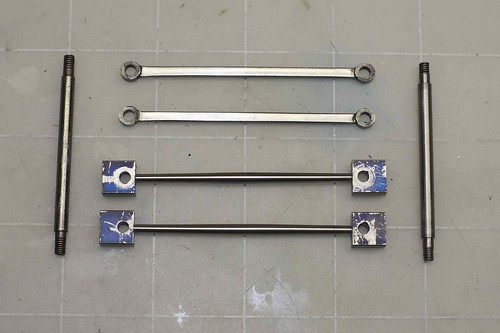
Those go to 3/32" at the ends. The top one is a little non-concentric, but since these parts don't rotate I don't think anyone will notice ;D Obviously I have to finish the ends.

Those go to 3/32" at the ends. The top one is a little non-concentric, but since these parts don't rotate I don't think anyone will notice ;D Obviously I have to finish the ends.
- Joined
- Oct 29, 2011
- Messages
- 284
- Reaction score
- 2
More progress has been made!
Of course I managed to mess up one of the valve links on the rounding table:

Note to self: add end stops to rounding table! Second note to self: when using larger end mill, don't rotate table as far! I'm too keen to get things running, so I'll come back to making another one.
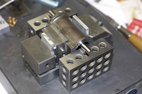
It was bugging me that the sides of the valve chest, the cylinder casting and the valve cover didn't line up, so set up things in the vise to give them a once-over with an end mill. Here's my setup to get things parallel to the cylinder bore:
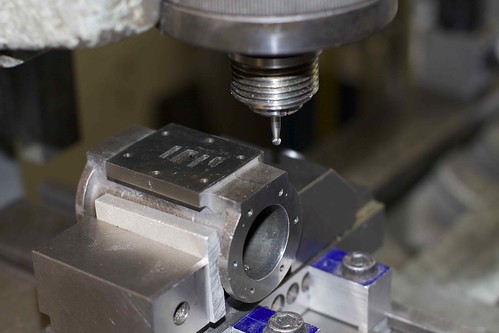
I trimmed the top and bottom of the valve face on the cylinder casting with a small spherical burr (that came with a dremel; I don't have a ball-end mill of the right size):
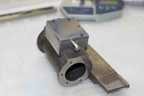
I then also put the valve chest in the 4-jaw, and cleaned up the valve guide for some bling:
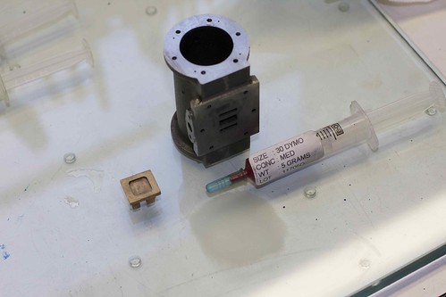
Finally I polished the valve itself, and the valve face with three grades of diamond lapping paste, and found a great way to leave frosted sections on my glass plate ;D
Here's what she looks like back together now:
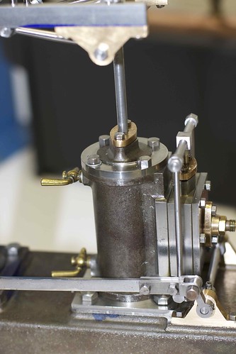
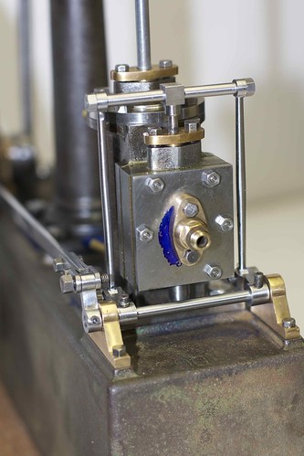
Excuse the blueing on the cylinder cover and elsewhere. I still have to attack that hard spot once the carbide drills arrive (hence the only 5 bolts).
The cylinder head bolts also need work. I'm thinking about going for a slightly more authentic look with studs on these and the main bearing bolts, but that could be a lot of fiddly work.
Of course I managed to mess up one of the valve links on the rounding table:

Note to self: add end stops to rounding table! Second note to self: when using larger end mill, don't rotate table as far! I'm too keen to get things running, so I'll come back to making another one.
It was bugging me that the sides of the valve chest, the cylinder casting and the valve cover didn't line up, so set up things in the vise to give them a once-over with an end mill. Here's my setup to get things parallel to the cylinder bore:

I trimmed the top and bottom of the valve face on the cylinder casting with a small spherical burr (that came with a dremel; I don't have a ball-end mill of the right size):

I then also put the valve chest in the 4-jaw, and cleaned up the valve guide for some bling:

Finally I polished the valve itself, and the valve face with three grades of diamond lapping paste, and found a great way to leave frosted sections on my glass plate ;D

Here's what she looks like back together now:


Excuse the blueing on the cylinder cover and elsewhere. I still have to attack that hard spot once the carbide drills arrive (hence the only 5 bolts).
The cylinder head bolts also need work. I'm thinking about going for a slightly more authentic look with studs on these and the main bearing bolts, but that could be a lot of fiddly work.

$649.00
$699.00
FoxAlien Masuter Pro CNC Router Machine, Upgraded 3-Axis Engraving All-Metal Milling Machine for Wood Acrylic MDF Nylon Carving Cutting
FoxAlien Official

$426.53
DM14 Engine Build Kit, Metal Engine Build Model Great Metal Material for Engineer for Factory
Easoger Official

$99.99
$109.99
AmTech300 - Boiler Treatment Professional Strength (Rust Inhibitor For Outdoor Wood Boilers)
Alternative Heating & Supplies

$188.98
TM NEXDYNAMI RE41157 Water Pump Compatible With/Replacement For/John Deere 6200 7400 6300 6600 6500 6400 7220 7600 7200 RE41157
VIVID MARKET CORPORATION

$40.02
$49.99
Becker CAD 12 3D - professional CAD software for 2D + 3D design and modelling - for 3 PCs - 100% compatible with AutoCAD
momox Shop

$39.99
$49.99
Sunnytech Low Temperature Stirling Engine Motor Steam Heat Education Model Toy Kit For mechanical skills (LT001)
stirlingtechonline

$158.69 ($1.42 / oz)
Replacement Combustion Chamber Kit, Burnham V8 and V8H, 1-6 Sec, 108136-01, 1129
Plumbing Planet
Harold Lee
Well-Known Member
- Joined
- Apr 23, 2008
- Messages
- 236
- Reaction score
- 2
Simon,
It looks and runs great. I just love watching a beam engine working. I am really enjoying watching your restoration and I have learned a good bit from you on set up and fixturing parts for machining. Keep up the great work!!
Harold
It looks and runs great. I just love watching a beam engine working. I am really enjoying watching your restoration and I have learned a good bit from you on set up and fixturing parts for machining. Keep up the great work!!
Harold
Wow Simon, you've got that so it slows way down, nicely done. I've said it before and I'll say it here, it's a treat to see how you set things up and have been successful in getting most all of the sins the original builder factored in. And ridded it of that gaudy metallic blue paint scheme. I can't wait to see what your final bling-bling has in store for us. Thm:
BC1
Jim
BC1
Jim
Wow, that's just lovely - when you can run it that slow then you've done it right.
Thanks for the vid.
Ken
Thanks for the vid.
Ken
- Joined
- Oct 29, 2011
- Messages
- 284
- Reaction score
- 2
OK, now I know that this thing is going to run, it's time for some cosmetic cleanup!
I was very glad to get to cleaning up the bearing oil cups. It had ugly soldered-on cups, so first thing I did was to unsolder them:

Then I touched an end mill to the top of the bearing to make a nice seat for the cup, and drilled and tapped 1BA, being careful not to go through to the bore. A smaller thread would not have worked due to the existing hole.

Now to make some oil cups to fit! I started with some 3/8" brass bar, and sketched out some rough dimensions for oil cups in my notebook. First, I took about 1/2" of the bar down to 0.312", which is the largest diameter of the cup, which is the base. Then I reduced 0.2" at the end to 0.21", and threaded 1BA (fitting to the bearings as I went, since the threads were pretty short). I drilled a small hole (#58 from memory) about 1/2" in. Then I turned the rough profile of the rest of the cup, basically marking the diameter changes with a small grooving tool, and parted off.
I made an aluminum fixture with a 1BA threaded hole, and screwed the cup into it for turning and filing the other end. After some careful turning and filing, I ended up with something like this (not quite finished yet):
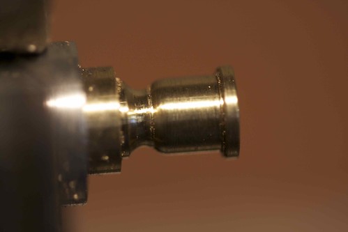
This was my first attempt, when I was planning to go with a hex base for tightening, but later decided that this made it look too tall, and that I could just hand-tighten. Anyway, here's my prototype cup in place:
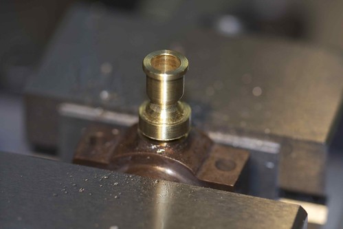
This cup later broke because I drilled the inside too deep ;D
I roughed out 4 more cups, seen here in their respective bearings, with the prototype to the top right, and the fixture in the lower right:

A bit of filing and sanding tomorrow should leave me with 4 nice oil cups. That should add a bit of bling!
I was very glad to get to cleaning up the bearing oil cups. It had ugly soldered-on cups, so first thing I did was to unsolder them:

Then I touched an end mill to the top of the bearing to make a nice seat for the cup, and drilled and tapped 1BA, being careful not to go through to the bore. A smaller thread would not have worked due to the existing hole.

Now to make some oil cups to fit! I started with some 3/8" brass bar, and sketched out some rough dimensions for oil cups in my notebook. First, I took about 1/2" of the bar down to 0.312", which is the largest diameter of the cup, which is the base. Then I reduced 0.2" at the end to 0.21", and threaded 1BA (fitting to the bearings as I went, since the threads were pretty short). I drilled a small hole (#58 from memory) about 1/2" in. Then I turned the rough profile of the rest of the cup, basically marking the diameter changes with a small grooving tool, and parted off.
I made an aluminum fixture with a 1BA threaded hole, and screwed the cup into it for turning and filing the other end. After some careful turning and filing, I ended up with something like this (not quite finished yet):

This was my first attempt, when I was planning to go with a hex base for tightening, but later decided that this made it look too tall, and that I could just hand-tighten. Anyway, here's my prototype cup in place:

This cup later broke because I drilled the inside too deep ;D
I roughed out 4 more cups, seen here in their respective bearings, with the prototype to the top right, and the fixture in the lower right:

A bit of filing and sanding tomorrow should leave me with 4 nice oil cups. That should add a bit of bling!
Lesmo
Well-Known Member
- Joined
- Mar 1, 2011
- Messages
- 142
- Reaction score
- 16
Nice work Simon, I have just caught up with your rebuild and am impressed by the way you approached the task. You must have everything pretty much spot on to be able to run it so slowly, which is how I like to see a beam engine run. Congrats.
Les :bow:
Les :bow:
- Joined
- Oct 29, 2011
- Messages
- 284
- Reaction score
- 2
Four oils cups done:
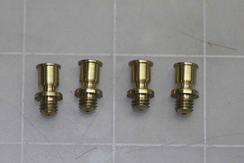
and in situ on the cleaned up bearings:
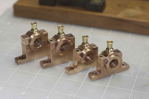
I'm really not sure how to finish the bearings. I don't like the high gloss look, so I might go at them with a green scotch pad. They're pretty dinged up and non-square, and the holes are all over the place; stuff that I can't really fix without making new ones. I just think of it as adding character to the engine
While fiddling with brass work I decided to fix up the cylinder drain cocks; I needed some aluminum washers of the right thickness for the cocks to tighten to the right position, so turned and drilled a piece of scrap, and parted off a few washers of different thicknesses:
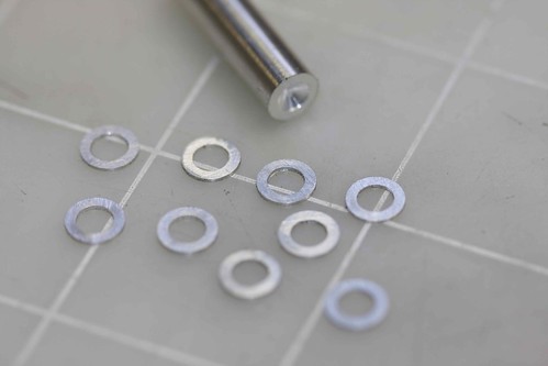
I found that I could just peel off the burr left from parting and clean up the washers with a countersink.
What occupied the rest of the day was reaming the bearing blocks. It took me a while to figure out a good setup for the crankshaft bearings. I ended up with a couple of 1-2-3 blocks square to the table, with the castings clamped, and some support under the ends:
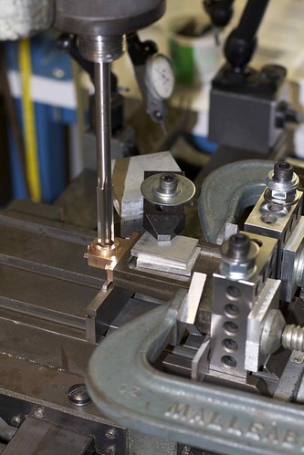
The way I got the table positioned right was to put some 7/16" bar in the mill, and approach it with the part, wiggling the carriage hand wheel and advancing the cross slide gradually until the bearings just seated on the bar:
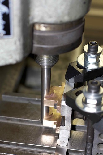
I did this with the bearings loose on the casting, then tightened up the bolts to start off everything straight. Then I could bolt the bearing caps on, put the reamer in a collet, and ream. I kept the cross-slide in the same position (gibs tightened down) for the main bearing on the body, and the bearing on the crankshaft support, so that they match vertically.
I did the bearings on the top of the column as well, and found that one was about 10 thou shorter, so made a brass shim to go that one. The beam spindle is also a tad undersize, so I put bits of paper between the bearings for reaming with the hope that they'll be nice a snug that way.
I haven't reassembled yet, so it will be interesting to see if that affects the running. But I'm glad I got the reaming done, even if it didn't take much off!

and in situ on the cleaned up bearings:

I'm really not sure how to finish the bearings. I don't like the high gloss look, so I might go at them with a green scotch pad. They're pretty dinged up and non-square, and the holes are all over the place; stuff that I can't really fix without making new ones. I just think of it as adding character to the engine
While fiddling with brass work I decided to fix up the cylinder drain cocks; I needed some aluminum washers of the right thickness for the cocks to tighten to the right position, so turned and drilled a piece of scrap, and parted off a few washers of different thicknesses:

I found that I could just peel off the burr left from parting and clean up the washers with a countersink.
What occupied the rest of the day was reaming the bearing blocks. It took me a while to figure out a good setup for the crankshaft bearings. I ended up with a couple of 1-2-3 blocks square to the table, with the castings clamped, and some support under the ends:

The way I got the table positioned right was to put some 7/16" bar in the mill, and approach it with the part, wiggling the carriage hand wheel and advancing the cross slide gradually until the bearings just seated on the bar:

I did this with the bearings loose on the casting, then tightened up the bolts to start off everything straight. Then I could bolt the bearing caps on, put the reamer in a collet, and ream. I kept the cross-slide in the same position (gibs tightened down) for the main bearing on the body, and the bearing on the crankshaft support, so that they match vertically.
I did the bearings on the top of the column as well, and found that one was about 10 thou shorter, so made a brass shim to go that one. The beam spindle is also a tad undersize, so I put bits of paper between the bearings for reaming with the hope that they'll be nice a snug that way.
I haven't reassembled yet, so it will be interesting to see if that affects the running. But I'm glad I got the reaming done, even if it didn't take much off!
- Joined
- Jul 3, 2010
- Messages
- 278
- Reaction score
- 10
Very nice job done Simon, like the creativity on the setups you make!
If you don't mind I will borrow the looks of your oilers for my 10H build, like them a lot.
Enjoy the finishing bits and parts, regards Jeroen
If you don't mind I will borrow the looks of your oilers for my 10H build, like them a lot.
Enjoy the finishing bits and parts, regards Jeroen
- Joined
- Oct 29, 2011
- Messages
- 284
- Reaction score
- 2
I did various bits of cleanup today. First thing was to tighten up the eccentric strap by filing down where the two parts meet. There are some odd markings on one side of the strap:
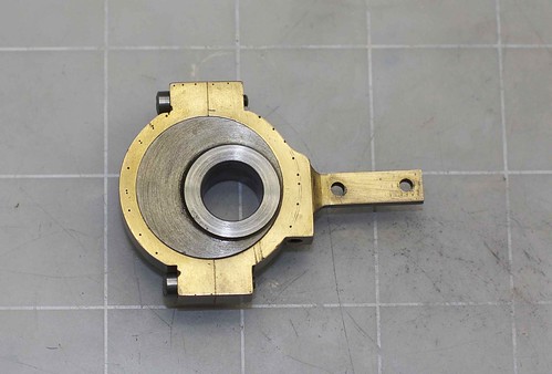
which look like filing guides, perhaps? I like them, so I'll just leave the finish as it is.
Next up, I decided to polish the external surfaces of the beam. This required taking a file to the casting, since the two sides were not very well aligned, followed by a finer file and many levels of grit.
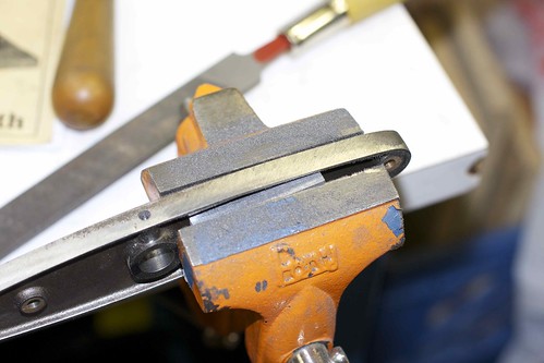
A bit hairy, but I think I ended up with an OK profile. It took a while to polish out the tool marks on the sides, and I didn't totally remove them, but it's better.
Then it was time for the flywheel! At first I had the flywheel on a mandrel (supported by the tailstock), held only by the grub screw. That was OK for the outer rim, but when trying to clean up the sides, there was enough flex in the wheel to cause chatter, leaving some ugly marks (visible in the image below). So I moved it to the faceplate, still on a 7/16" mandrel in a collet to keep it centered.

That worked much better, and allowed me to polish the rim and one side:

before flipping it over for the other side. Shiny!

which look like filing guides, perhaps? I like them, so I'll just leave the finish as it is.
Next up, I decided to polish the external surfaces of the beam. This required taking a file to the casting, since the two sides were not very well aligned, followed by a finer file and many levels of grit.

A bit hairy, but I think I ended up with an OK profile. It took a while to polish out the tool marks on the sides, and I didn't totally remove them, but it's better.
Then it was time for the flywheel! At first I had the flywheel on a mandrel (supported by the tailstock), held only by the grub screw. That was OK for the outer rim, but when trying to clean up the sides, there was enough flex in the wheel to cause chatter, leaving some ugly marks (visible in the image below). So I moved it to the faceplate, still on a 7/16" mandrel in a collet to keep it centered.

That worked much better, and allowed me to polish the rim and one side:

before flipping it over for the other side. Shiny!
Similar threads
- Replies
- 6
- Views
- 857


![MeshMagic 3D Free 3D Modeling Software [Download]](https://m.media-amazon.com/images/I/B1U+p8ewjGS._SL500_.png)


