Superfast
Member
- Joined
- Aug 25, 2008
- Messages
- 19
- Reaction score
- 0
Marv,
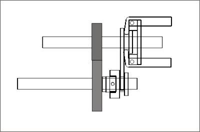
Nick pretty much hit it on the head. Here is a pdf file with some models of how the fork works with the cap screw cam.
http://www.scottsrc.com/machining/forkdetail.pdf
The first 2 pictures show the cam in the "hit" position with the linkage fork in place. The 3rd picture shows the cam in the "miss" position.
In the parts drawings you can see that the fork guide has a slight "step" cut into it. The linkage fork rides in this step, when the cam is pulled away or not in the "hit" position, the step keeps the fork aligned. Hopefully the pictures clear it up for you.
Nick,
You are correct, sometimes the cam will strike the side of the fork, but as the crank rotates it drops into place and hits on the next stroke. I didn't use a roller/bearing style fork on my engine, mainly because of size. Instead it is simply a flat surface on the fork, seems to work pretty well. I made the original fork from brass and it is showing a little wear on it (probably cause I like the sound of the engine and can't quit running it!) from the cam "sliding" into position. If anyone wants to use this style of fork on their engine I would recommend building the fork out of steel, it should hold up a little better. I may end up going that way myself, but currently working on the new frame/cylinder design.
I wonder how the roller bearing style linkage would work with the cap screw cam design? Would it grab the edge of the bearing instead of "sliding" off a flat fork design?
Scott


![TurboCAD 2020 Designer [PC Download]](https://m.media-amazon.com/images/I/51UKfAHH1LL._SL500_.jpg)


![DreamPlan Home Design and Landscaping Software Free for Windows [PC Download]](https://m.media-amazon.com/images/I/51kvZH2dVLL._SL500_.jpg)


