small camshaft

Home Model Engine Machinist Forum

Help Support Home Model Engine Machinist Forum:

This site may earn a commission from merchant affiliate links, including eBay, Amazon, and others.

anday1

Well-Known Member
Joined
Aug 2, 2022
Messages
69
Reaction score
50
Location
york
hi
I wondered if anyone has information to make the camshaft as shown in the DRG. I have even contacted CNC machinists ...they say NO...camshaft makers ..they say NO. never even got to how much!!!!
So I am going to bite the bullet and make them myself, with manual machinery.
Feel free to advise and I would really appreciate any help


All the best
Andy
 

Attachments

  • Scan 62.jpeg
    Scan 62.jpeg
    188.9 KB
  • boxterengine.jpg
    boxterengine.jpg
    309 KB
I just remember the video I saw on cam grinding.


No Idea how precise it all needs to be. Maybe you can make shaft and cams in separate pieces silver solder them together and grind the cams? If you design a pattern you might even get away with a 3d printed cam (for the grinding, not for the motor).

Please post some pictures what you did.

Greetings Timo
 
I don't know why a CNC company would fight shy of tackling those, 'cos the flanks are straight! I would put a keyway in the blanks for alignment, and make a filing fixture with two keyways. Your designer has actually been quite kind. Westbury's method, whilst effective, had cam flanks with an approximation of a cycloidal curve to them, and that's what necessitates the complicated fixtures. Lucky you, you don't need to trouble yourself with such high jinks. Only complication is that those cams are so damn small!

You'd best let us have a look at the lifters- to see what can be gotten away with.

-Andrew UK
 
With flat shanks they are quite easy if you have a rotary table or indexer of some sort, no need for lathe jigs as they are for curved flanks.

Start with some larger bar, 16mm will do and work on the end of that first facing and reaming the hole in the lathe.

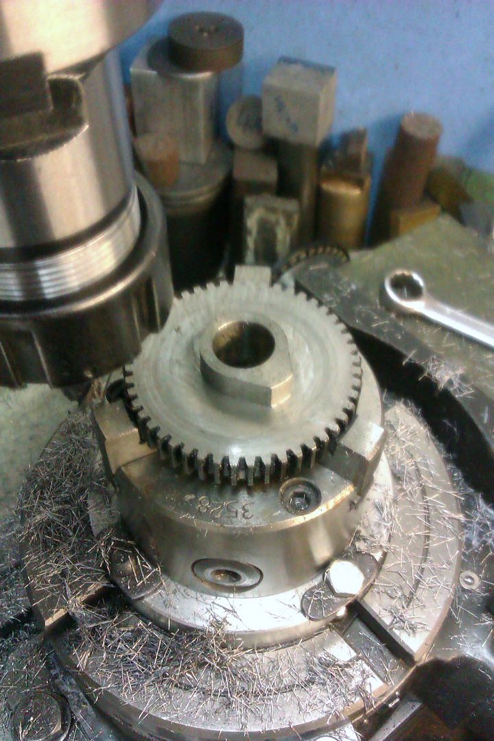
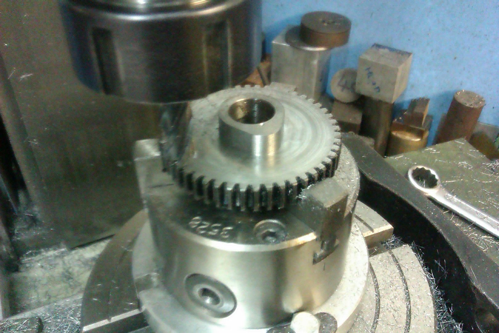
Then over to the mill with the rotary table set horizontal locate the ctr of the workpiece and zero the X&Y axis as well as the rotary table to zero. Then with say a 6mm cutter make a few cuts working in until you are cutting a flat face 5mm from the ctr so cutter will be offset 8mm.

Rotate teh table say 4deg and make another pass, then rotate 4 deg and make another pass, keep doing this until you have the basic lobe with it's two flanks (216,81deg total). You can then either reposition to round the nose of just do it with a file.

Part off and harden

Something like this, first pic after the series of tangental cuts and one clean up cut done winding teh table through teh requited angle. Second shot repositione dto mill the nose radiud

IMAG3632_zps8txwfrre.jpg


IMAG3635_zps50tjf32o.jpg
 
Last edited:
jason ...i will try that makes total sense.............i am now on my 7th request to a CNC machinist...they don't even mention the price....just say NO

many thanks appreciated
andy
 
Heres the lifters
 

Attachments

  • Scan 66.jpeg
    Scan 66.jpeg
    80.6 KB
Best forget CNC shops. As paid jobs, I don't know what shop rates are nowadays, but expect to pay 75- £80 setting time before they pick up another spanner. I dropped off a job once as a "favour" job. I picked the piece up again two years later, still with the busted 10 BA tap in it. Companies seem fascinated by miniature engineering, but making a living always comes first!

Road to hell, etc.
 
Lifters assuming that is a hemispherical end you can either freehand grind a 2mm radius into a small HSS tool blank, corner of a bench grinder wheel will do to get the basic shape and finish by filing while it is rotating in the lathe. If you want a bt more precision then drill a 4mm hole in sone gauge plate, cut away some plate to leave a 1/4 radius, harden and use that as a form cutter. Or buy a cheap router bit or rounding over milling cutter with 2mm radius and mount that in your tool post to cut the convex end.

Concave end is just a shallow spot drilled dimple and then use a 2mm dia ball nose milling cutter in the lathe tailstock chuck to do the other end.

As for CNC now that I have one cams are a breeze but most people would be put off by what a commercial shop would charge for a small one off. It's not the cutting time which is only a min or so each but the time to do a drawing, do the CAM, set up the machine, etc
 
I'll let you in on a dirty trick. When I worked in an auto shop, we used to make concave form tools. Ground as best as we could (pretty damn good) we then used to run a drill, gripped by the flutes, at top speed with fine grinding paste. Lapped our concave tools off the shanks, to a mirror finish.
 
Andy,

Consider making a trial lobe in aluminum first. Once you are comfortable with the process make individual cam lobes, make a witness mark at the center of the lobe them locktite onto the shaft using the witness marks to align them I have even just used super glue and if you like the result either locktite them or pin them in place. Works for me.
 
Thinking about it a bit ,ore it may be better to turn a "bobin" shape and then cut that in a similar way but with the rotary table vertical so work is horizontal, come down until end of tool is 5mm above ctr line and then start making your cuts. You can then move along to the second cam of the pair and do that 90 or 93deg out of phase with the first.

boxer cam.JPG
 
ok i am going have a go i will get back to with my progress i will take some pics...Thank you ALL for taking the time to think through my challenge

andy
 
Hi Andy,
Just a tip my Father used on many different jobs. His lathe was very old (1920s? - had RH threads for lead and feed screws, etc., not LH like modern machines...). But it had a back gear. So he filed a small sector of mild steel to fit a gear of the back-gear, on a rocker arm, and used this to lock the lathe mainshaft at a certain position, then by indexing to the next tooth etc. he could divide the rotation by the number of teeth on the Back-gear (possibly 60? - I can't remember!). Thus the mainshaft became a dividing head, and he could manually drive a tool (fine-cut) axially along the part - set as a shaper tool would be, and finely cut a cam profile that he wanted for something.
Of course, he had a component with 6 degree cut lines along it, but was very close to the profile and careful filing reached the profile he wanted to a suitable accuracy.
This sort of task can be hugely time consuming, but that's the world that existed "back-then" - People took the time to do things manually because they could, and didn't have machines to speed things up.
To me, modelling often uses the processes we would not find in a "modern workshop" because they didn't exist when the "original" was made... And I doubt you have a lathe with a back-gear? - But can arrange an alternative if this is useful to you?
Anyhow, it was the way he converted the lathe to use it as a dividing head and shaper, which I understand was an early way to make cams, etc.
K2
 
Looks like Andy has a couple of Myfords so the BULL gear can be used for indexing the spindle on those. But he also has a mill so that will make much easier work of it.

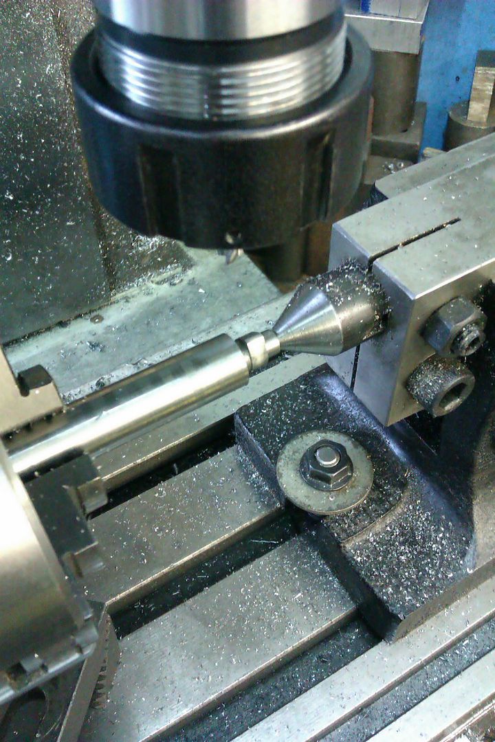
If Andy wants to punch the numbers into Cam-Calc that will also do the rounded nose at the same setting, can be downloaded from my dropbox, 2degree increments will be more than ample
https://www.dropbox.com/scl/fi/roit...draw.xls?dl=0&rlkey=uyf4ql1k5qfp2ws5d6pyygvb4
IMAG3004_zpsajzepwvv.jpg
 
Last edited:
I just remember the video I saw on cam grinding.


No Idea how precise it all needs to be. Maybe you can make shaft and cams in separate pieces silver solder them together and grind the cams? If you design a pattern you might even get away with a 3d printed cam (for the grinding, not for the motor).

Please post some pictures what you did.

Greetings Timo

awesome video!
 

Latest posts

Back
Top