Slightly Loco

Home Model Engine Machinist Forum

Help Support Home Model Engine Machinist Forum:

This site may earn a commission from merchant affiliate links, including eBay, Amazon, and others.

shred

Well-Known Member
Joined
Jul 19, 2007
Messages
1,949
Reaction score
7
I decided I wanted my next engine to be able to move itself about. Long story short, I ended up finding the plans for a tiny narrow-gauge geared live-steamer that will run on O-gauge track and decided to give it a go. Turns out the plans are in metric and I'm not. But my original plan is essentially to leave the metric dimensions more or less in place and make a metric model with imperial holes.

It's never quite that easy.. it'll be an interesting challenge.

It's only the second day and my plan sheets are already covered in scribbles, noting changes from one place to another. It doesn't help that I'm also modifying the design somewhat and the gears I have on hand aren't the same as the plans call for.

I've already broken one 2-56 tap and screw. The first attempt to remove the broken tap involved soaking the part in muriatic acid, based on some advice I found on the internet. That worked very rapidly.. at eating away the aluminum. Five minutes later the part was 80% of it's starting size and it was even odds if the tap would dissolve out or the aluminum would dissolve around it first :mad: So I made another part and promptly snapped a cap screw off in it. Went back to the internet for advice and spent most of the afternoon trying to Alum it out to no avail. I finally drilled it out very slowly with a carbide PCB drill and retapped.. slightly off center. :eek: Oh well, I think I can cover for it later.

Here's the progress to date-- one running plate, two side frames, two end beams, eight bushings and 4 axles (the gears I didn't make). It's already an unholy mix of metric and imperial that will probably have Marv reaching for his largest mallet. :eek: --the basic measurements and holes holding things together are even metric values-- the holes and screw sizes themselves are imperial and the axle hole spacing is determined by the gear train and isn't a convenient number in either system. Some of the other holes are spaced imperial so I can bolt things on later made on the manual machines...


Frame.JPG
 
shred said:
IWent back to the internet for advice and spent most of the afternoon trying to Alum it out to no avail.

I've had success with Alum on a broken tap in brass but the process took days not hours. That said I don't know if I got the mixture strength correct etc.

Good luck with the rest, looks good so far. If you hadn't told us about the problem we would never have known..

Al
 
You did get the mix right Al, Alum is a slow working process, not sure of Its caustic properties in aluminium though. I remember vaguely trying to dissolve/loosen a broken stud in a motorcycle bit and I think it got a bit messy using Alum. OK though on CI and Brass. Regards Ian.
 
SignalFailure said:
Nice start Shred! Are the plans online somewhere or did you buy them?

would like to know also.
looking good, keep pics coming ;D
 
The plans are available online. Search for 'cracker' and 'live steam' and they should turn up. It's 6 pages of drawings and nothing else, so you get to be creative trying to figure out what goes where and when, including all the plumbing (there are some much more detailed free plans for different engines available. 'Idris', for one that looked much better documented). I know few live-steamers to pester for advice later on.

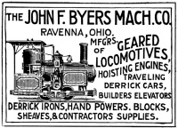
For even more mixed-ancestry fun, the 'Cracker' plans are loosely styled in the British/European style, although the original prototype was a very short-run US industrial loco, the 'Byers'.. I believe there have been more designs off it than original examples, Cracker and Cricket (also worth a search), to name two. I'm going to build mine more in the US style with a proper roof, though I'd hate to be the engineer that shares the cab with most of the boiler.

advert_engineering_news-t200.jpg


The alum seemed to be doing nothing at all after several hours at simmering temperatures besides lightly etching the aluminum, so I decided to try the carbide drill-- at least that would expose more surface area to be attacked if it didn't work.

More build notes:

The gears are replacement RC car pinion gears-- available locally and ~$3 each. 12T and 35T were the smallest and largest sizes available in 48P at the hobby store, for an almost 3:1 gear ratio. Once the store gets more in, I'll add a gear to the other axle. They're only on there at the moment to test fit and mesh anyway.

Another change I did was to thicken up the frame plates-- the plans call for 1.5mm (1/16") brass, but being short on that, I switched to 3mm (1/8") Al. 1/16" felt kinda flimsy anyway. That cascaded changes into the beam ends, axles and bushings. [edit: it also prevents Gauge-1 operation with longer axles unless you thin the frames]
 
that vid was cool ;D

anyone have links to the plans? I searched but no plans are coming up. :'(
 
shred said:
I've already broken one 2-56 tap and screw. The first attempt to remove the broken tap involved soaking the part in muriatic acid, based on some advice I found on the internet. That worked very rapidly.. at eating away the aluminum. Five minutes later the part was 80% of it's starting size and it was even odds if the tap would dissolve out or the aluminum would dissolve around it first
I don't know where you got that peice of bad info. but it's suppose to be NITRIC acid. Ive done it
several times back a few years ago at the university. Getting Nitric acid may be a problem to the
general public. Have any connections at a university chem dept.?
...lew...
 
Lew Hartswick said:
I don't know where you got that peice of bad info. but it's suppose to be NITRIC acid. Ive done it
several times back a few years ago at the university. Getting Nitric acid may be a problem to the
general public. Have any connections at a university chem dept.?
...lew...
Dad's a chemistry prof, but a thousand miles away. Several places on the net say muriatic is ok .. don't believe them. (I checked first because I had vague memories of creating hydrogen gas via acid and aluminum foil as a kid)

Thanks for the video-- I hadn't seen that one. I note that engines of this sort are sometimes known as 'piddlers', due to the water trail they can leave, so you might not want to run one across momma's new carpet.

Anyway, I got the wheels made tonight. I wanted to use a profile tool to cut the tread profile so that was a good excuse to play with my rarely used T&C grinder. The form tool worked ok (I ground it slightly wrong, though usable), but chattered like mad (I told my GF "how else did you think they get the screeching into train wheels? ;)). Part of the problem is I roughed out the 4 wheels separately, then returned them to a mandrel to profile with the form tool. That didn't work so well because trying to feed through the chatter just made them spin on the mandrel. Were I to do it again, I'd think about cutting all the wheels onto one bar, profiling them and then parting them off, or making a form tool capable of doing the roughing as well.

In theory, the long axles allow wheels to go on the outside for gauge 1 track and on the inside for gauge 0 track, but note thick side rails make that difficult.


FrameWhls.JPG
 
You can get pure nitric acid in pretty small quantities from Sigma-Aldrich (http://www.sigma.com). You have to register and be approved before they will let you order anything, but I think it is no problem getting approved (I'm a chemical engineer, and was approved through work, so I'm not completely sure on that).

You can also order somewhat dilute (~70%) nitric acid from http://www.sciencecompany.com - $22 for a pint, $33 for a quart. There is a hazardous material charge added to the price, supposedly, and it will only ship via ground (I'm sure there is a similar company in Europe that everyone over there could use).

A word of warning with nitric acid - it is some nasty stuff! Do not store it near other acids or lead-acid batteries (the vapors will react). Like all acids, if you want to dilute it, add small amounts of acid to water (not the other way around!), and stir it, allowing it to cool before adding more acid. Wear rubber gloves when handling, ensure plenty of ventilation, and wear full goggles or a face shield. Also, have a big box of baking soda nearby to clean up spills.

I would also look for some disposable plastic pipettes for dispensing the stuff, instead of trying to pour it out of the bottle.
 
While not distracted by speed-builds of finger engines, or monowheel cycle web pages, I made a few parts for the Loco wobbler engine. Of course, right after I built the standard I realized why the standard is drawn like it is, and not as I made it.. ah well, I can fix it later, so no harm done but a little extra shop time. Chalk it up to a fit of reverse-metrification blindness. :p

Other notes: I'll probably have to redo the piston. That was a practice piece that turns out to fit well, but I don't think drill rod and live steam get along well long-term. The standard, as I note, needs to be redone to fit in place of a frame bushing (that bit of cleverness in the plans escaped me until now). I made the cylinder out of one piece of brass versus the much thinner-walled tube-and-endcap with soldered valve plate in the plans. Shouldn't make much difference one way or the other-- the blind hole required me to make up a D-bit reamer to finish it up, but I can skip soldering anything a while longer. The bore and stroke are very similar and I think this will look a little more like the original, with a big vertical steam engine on the side.

For the 'what order do I do things in?' thread, think about this piston-- lots of ways to make it, but it can get ugly if you get the ops in the wrong order, especially the parallel flats with a perpendicular crank hole (the thin sides are rounded at the piston diameter so the cylinder extension acts as a trunk guide)

- Roy

And for those that like to contribute-- here's one I'm idly pondering. The wheels (26mm x 6mm or ~1" x .25", 1/8" axle, flanged train-style, as seen previously) are drawn with no means of attaching them to the axles. I had originally planned to use loctite to fix them in position, but I'm liking that option less now. So-- shallow-angle-drill for tiny setscrews from the back? Affix to shaft collars? Bore and redo the hubs? Stick with adhesives? Other ideas?


EngineParts1.JPG
 
shred said:
The wheels (26mm x 6mm or ~1" x .25", 1/8" axle, flanged train-style, as seen previously) are drawn with no means of attaching them to the axles. I had originally planned to use loctite to fix them in position, but I'm liking that option less now. So-- shallow-angle-drill for tiny setscrews from the back? Affix to shaft collars? Bore and redo the hubs? Stick with adhesives? Other ideas?

AFAIK they're usually taper-pinned and glued but as there won't be much load I guess grub-screws would do (with a dimple on the axle maybe?).

Nice work on the cylinder ;)
 
Taper pins I could maybe do, but they might be very fiddly to install since the wheels usually go on the inside of the frame.

Anyway, on progress, I got the rest of the wobbler engine built and somewhat running on air (photos & video later), but along the way found another bug in the plans, or at least how I read them-- Sheet two shows a couple holes in the Port Block; one either side of the crank hole that appear to be there to bolt the port block to the frame, and my initial plan was to tap the frame... You can see the un-tapped holes in the frame shots above immediately beside one of the center bushings.

But.. there's only 1mm or so clearance for bolt heads with the crank in place.. that's not going to work. Time to think of a plan 'B'.


Here's the video of the wobbler engine running, on the bare frame with about 10 PSI air.

As you can see, I solved the clearance problem with some countersunk holes and flat head screws, but as I'm not liking those, they'll have to be replaced sooner or later. Sorry about the lack of light... seemed bright enough in there for me.

[youtube=425,350]Z1Rc9fgv-xg[/youtube]

Note, if your wobbler only runs one direction and with the spring really loose, you may have the exhaust hole drilled in the wrong place. If it's not off by much just enlarge it a little. Makes all the difference in the world. ::)
 
shred I love slow engines.

I have never seen a wobbler running that slow.
Great Work!

Rick
 
rake60 said:
shred I love slow engines.

I have never seen a wobbler running that slow.
Great Work!

Rick
ok, so I'd better confess before everybody else with a wobbler feels inadequate ;) I cheated a little.. I filmed it at 300 frames per second as opposed to the usual 30, so the video is effectively running ten times slowed down ;D ;D I was trying to figure out what the hitch at the top of the stroke was caused by, thought the video was cool and waited to see if anybody noticed the unusual slowness of a 5/16" bore/stroke wobbler..


Latest posts

Back
Top