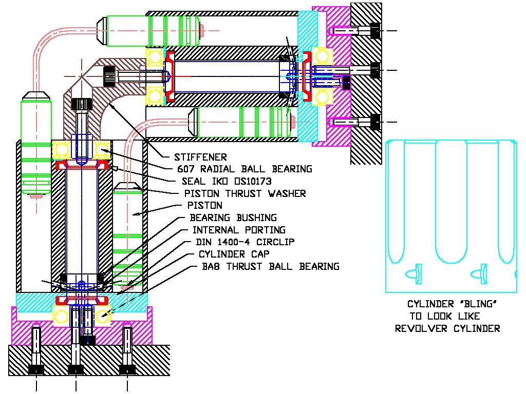
I am thinking of building a couple of these ridiculous looking things but I need to get something figured out. I am going to suck fuel thru the block to lube the crankshaft. The cam and crank exit the front of the motor.
Is putting a sealed bearing on the shafts at the front enough to seal the crankcase or do I need an o-ring somewhere?
How are the RC engines sealed up?

View attachment aaaaSingle.pdf


![DreamPlan Home Design and Landscaping Software Free for Windows [PC Download]](https://m.media-amazon.com/images/I/51kvZH2dVLL._SL500_.jpg)