Setting up my new shop

Home Model Engine Machinist Forum

Help Support Home Model Engine Machinist Forum:

This site may earn a commission from merchant affiliate links, including eBay, Amazon, and others.
Somewhere I do have a concrete floor but it's disappeared over the years.

Beaver1.jpg


This is an old photo of the back place, since this was took I have managed to shoehorn another full sized CNC in there.
At one time we were under the approach path to East Midlands Airport but they have diverted the planes now as it's affecting the compass's on the aircraft coming in to land ::)

 
John,
Oh! dear me, when did the bomb go off?

How do you get around H&S with that lot? You are liable to get the a**e ripped out of your jeans just by walking thru there. Or is it classed as a private workshop?


But before going any further, I have something to tell you.
I have been banned from painting the insides of my shop. A long story, but my own fault. Just leave it at that. So I have to look at ugly walls for the rest of time.


Now onto what I have been up to.
When I put a new machine in, I like to have the tooling for that machine in the area around it. Other tooling, like mics and verniers and shared tooling, goes into an area between them. By doing it that way, it saves having to root thru boxes to get what you need to do the job.
So I selected a safe place, very close to the machine, got what tools I need, and made a shelf and fittings to fit it all in. Plus a little room for expansion if needed.
Everything has it's own little place, and all are within easy reach.
All my normal cutters will go into the rack below the collets.

Heavyweight tooling, like RT and dividing head etc goes into a steel roller cabinet on the other side of the machine, complete with their related bits and bobs.

workshop67.jpg


So this is what it looks like when viewed from a distance, notice how little space is really needed if a bit of thought is put into it.

This system worked very well in my old shop, so I have stuck with it.

workshop68.jpg


This shows how the area is protected from flying swarf when the machine is in operation.
Before anyone mentions it, no the handles won't hit the screen, and yes, I need to recast my lead hammer.

workshop69.jpg


I think the thing hanging under the DRO screen is for putting tooling into, the holes are just the right size for collets or tooling mandrels, but I don't like that idea. It will be a perfect place to put a clipboard for holding drawings, save having to use bench space to do that, and I hope it will keep them a bit cleaner.

Now going into the shop to sulk a bit more.

John
 
No problem with Health and safety, there something living in the coolant tank under that big lathe that loves H&S guys.
Last one that came in, there was a big rustle, a belch and no more problems.
 
What sort of vice is that you've got John?
Also, the boring head looks good, can you do things like loco cylinders with that? Was thinking of one for that purpose.

Many people do them bolted to the lathe cross slide with a boring bar between centres, however, my harrison doesn't have a slotted cross slide.

Nick
 
Nick,

It is a standard Vertex vice, it came as a freebie upgrade with the machine, but they are available from places like Chronos in all sorts of sizes to suit your machine from around £50+ upwards.

The boring head again, is available from most tool suppliers, and can be bought as a full kit of mandrel to fit your machine, plus a set of boring bars for around £40 for the 2" one, which will bore from about 1/2" up to about 3.5" diameter, or even larger if you fit a boring bar in the horizontal fixing holes. These are designed specifically to be used with a mill.

John

 
That's just the sort of vice I was thinking of getting., think I may go for a boring head too. I've seen them used in the lathe tailstock too, although I guess it's better and more rigid to have one in the tool post.
 
John, I know I am a novice but I think you have overlooked one very important item. I hope you don't mind me pointing it out but where oh where is the support for your tea cup! You need to consider this item soon.......... :big:
 
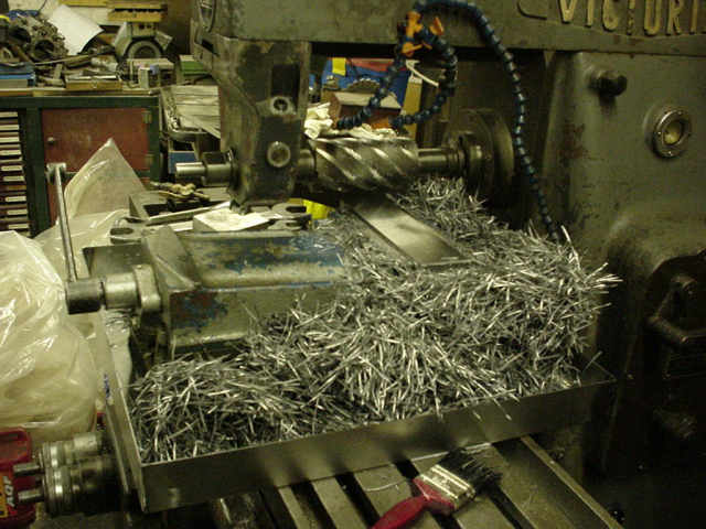
The problem with vises on milling tables is most of the time they hang off the table, no a big problem if you are machining dry but when using flood coolant it fills your boots up.

I have a series of sheet metal trays made up to fit different jigs and vises depending on how they want to fit the table and on what machine.
They have thru holes for the T bolts and also extra holes that line up with the tee slots for drainage.

milltray2.jpg


This is not a staged shot but an actual job on the big horizontal with full coolant, not the bed and surround are clear of chips.

If you get a job where flying chips are a problem then it's easy to file side screens to collect all the crap.

fourtoonehead.jpg


This was taken to show a speed increaser but it also shows the screens fitted to another of the trays.

Last pic probably shows better what would have gone into your boots ;D

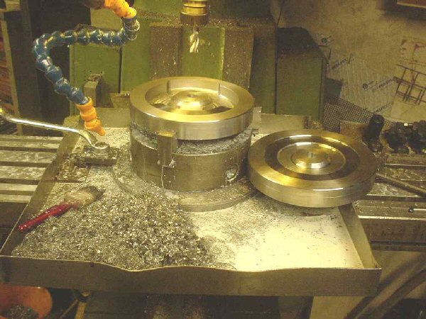
milltray3.jpg


This is a pair of flywheels for a vintage JAP vee twin being machined out.

.
 
Now that the mill has had a good going over, the final part of its checkout was due. How accurate are the slots in the table. This is a major factor when using a machine, because if they are accurate, it can save a great deal of time on your setups.

The first thing I did was to check each slot in turn, as far as I could, because the vice was still in position. Basically, there was no detectable runout over the whole length of the table, on all six slot sides. Looking promising.

workshop70.jpg


Then I measured the width of the slots all over the place, all the same reading, 0.625". Very, very promising.
I am really starting to be overwhelmed at the quality of this machine.

workshop71.jpg


While I was at it, I checked on the table clamps, and what effect they had when tightened up. On the Z axis, when tightened the DRO reading dropped by 0.0002", Y axis gave an increase of 0.0001" and there was no change on the X. These were all checked at different positions and all gave basically the same readings. So they were duly noted down for future reference, to be double checked with a DTI. The reason it is good to know these figures is that you can allow for the movement when setting up the cut.
It might seem stupid to a lot of you, to take such a long time and do so many checks on a machine.
Within ten days, I have this machine set up to the best of my ability, and I now know how it should behave when I start to use it in earnest. I took the opportunity to do it now, rather than make many mistakes over the comings months, and fixing it as I go along.

________________________________________________________________________

I am now happy to start using the machine.
I will start on something soft and work my way up.
So a lump on nylon in the vice, ground up my flycutter to my favourite shape and got ready to cut.
Again I will use this time to see how the machine performs with regards to speeds and feeds, what are the vibration levels like etc.

workshop72.jpg


First cut, 0.050", spindle speed at 2k and a fast feed on the power feed. Slight vibration coming from flycutter, but final finish and size were spot on. The semi circular guard works very well with the flycutter and managed to keep most of the chips around the vice area, with a few being thrown out the back.
Time to step it up.

workshop73.jpg


An 8" long lump of brass, this is for a job, so needs to be made exact on size. 5/8" minus 0.001" width, doesn't matter about he depth.
Same cut, speed reduced to 1600, same fast feed. Mirror surface finish obtained.
The bar was then squared up all round, and brought to width, 0.624", no detectable difference end to end.
Machine was now showing what it could really do.

workshop74.jpg


This is what it made, and it was made for a specific reason. To be a nice push fit into the slots on the table. Which it did perfectly.

workshop75.jpg


This bar was made for doing a specific job, and that was started today.
I will hopefully be finishing the project tomorrow and it will be posted under the appropriate heading.

John
 
My journey into the outlands is almost over.

Just had a phone call (we did away with drums and smoke signals years ago) to tell me my lathe will be delivered on the 28th of this month.

So about two weeks after that, as long as nothing major goes wrong, I will be operational again.

So look out all you with wobbly bling crowns, I will be back.


Back to tiling John
 
Let me see if i have this right.... Wife won't let you paint the shop.... so you are on your knees laying tile? Yeah... that works here....LOL

Steve
 
She is weakening.

My mate Tel and myself nearly had her agreeing this morning.

A few more tiles and we should have her eating out of our hands, she might even paint it for me.

Am I living in a dream world or what.

Boss Bogs.
 
The third major part of my shop upgrade arrived at lunchtime today.

Luckily, my friend Tel was here visiting, and without him my new lathe wouldn't have made it. The delivery came on a curtainsider, and it must have been loaded by forklift from the side. The pallet was too long to be handled with the pallet truck the driver had, in the position it was sited on the wagon, so Tel took over and and had it off in ten minutes, the driver didn't have a clue. It was also listed as only weighing 200kilos, in fact it is 450kilos. Someone has been cooking the books.


So anyway, after having signed for it as 'unchecked because of packaging' (covers me if anything is found damaged as it is unpacked). The first two bits came in stout cardboard boxes weighing about 30 kilos each (about 65lbs). These boxes contained the main lathe stand, no pressed steel here, welded up out of 1/4" plate, with a plate on the top that must be at least 1/2" thick, with the top faces machined level. The left hand one is the storage cupboard and access to the emergency stop foot operating pedal linkage. The one on the right is actually showing the rear face, and this contains a very solid suds pump and tank.

workshop76.jpg


Whenever you receive something like this, if possible cover yourself by taking photos of any damaged areas on the outside of the box, and at each stage of unpacking. Just in case there is damage, so you can prove that it was done prior to the final unpacking stage.
So the top was removed first. It came off fairly easily, so the box had been opened before.

workshop77.jpg


Protective packing peeled back and the first look at the new bit of equipment. It was given a full dose of looking at without touching anything, no damage as far as I could see. The whole machine is covered in a protective gunk that will eventually be removed.
In the bottom of the box was a very comprehensive toolkit, in a nice plastic toolbox, of the same type as came with the mill. Lots of bubble wrapped bags in there as well, all the bolts and fittings like DRO head, plus a load of extras I had ordered. Each bag was checked against the inventory and all was found OK, except I had ordered 20 standard tool holders and only 8 in there. On checking paperwork, the have back ordered another 12 for me.

workshop78.jpg


Once the loose bits were checked, time to check all the bits that were advertised to come with the lathe.
Under the lathe, bolted to the crate was a 10" face plate, again, fixed to the bottom of the box, in bottom right hand corner was an 8" four jaw independent. QCTP was in position already, as was suds pump pipework and DRO read heads.
I also noticed that only one chuck key was supplied, but on checking it out, it fit both supplied chucks and the camlock chuck locking, so it looks like someone has been doing their homework.

workshop79.jpg


The other half shows travelling and fixed steadies plus 6" 3 jaw, halogen lamp (including expensive bulb) and micrometer saddle stop (looks like a few mods needed on that, I like at least 3 stops).
Also note below the chuck on the bed, this has what is called a gap bed, where a section can be removed to allow much larger parts to be swung if needed. Not a thing to leave out permanently, as the lathe can easily twist out of shape, but OK if done occasionally for that 'special' job.

workshop80.jpg


So it looks like no damage as yet, and all bits are present.
Time to unpack a bit further.

workshop81.jpg


No sooner had I taken the front off, the nose on legs was in there, checking for nasties.
I was there soon after checking for damage. None at all found. So no phone calls yet to the supplier.

workshop82.jpg


Now this is one of the main reasons I went for this special model. Almost everything I need is on this front panel. The two top levers with arrows give me 18 speeds, the other one gives me leadscrew fwds/rev. I also have motor fwds/rev controlled by a handle on the bottom of the three shafts. The middle one is for cross feed and the top is the standard leadscrew.
The four knobs on the bottom control the speeds to both the top shafts for screwcutting and feed.
A full set of charts are provided on the front for speeds and feeds plus metric and imperial screwcutting. A set of change gears are supplied to change the machine between the two.
One thing I don't seem to be able to adjust to is the squareness of everything. I have always used machines that have voluptuous curves and rounded corners. I will have to see if I can get used to this minimalist approach to machinery.

workshop83.jpg


Another point I liked about this machine is the fact it has dual met/imp resettable scales on all controls, including the tailstock. So really it can be used as a machine for both standards, even without using the DRO.

workshop84.jpg


I have never been able to get close to one of these machines before now, as they never had any in stock, and I had to pre order this one three months ago. And they still have a backlog of orders.
I think the reason is, and Chester UK admit to this. The machine is grossly over specced for the price. They reckon it should be £500 dearer, and I would agree with that. In fact I got this at a much lower price than is shown on their website. Cash talks.

A had a good look thru the test report that came with the machine and found them very encouraging, from the tailstock being only 0.0015" higher than the spindle, to the 0.001" runout at the end of a 1ft long test bar sticking out of the spindle. To me, well within acceptable tolerances. But only time and tweaking will tell.

So now it is boxed up again. My mate Tel refused to get it on his back, and carry it into my shop, so I have now to wait until my machine moving man comes to do it for me. Hopefully sometime next week.

John
 
Bogstandard said:
My mate Tel refused to get it on his back, and carry it into my shop

Tell him 200 angry forum members are currently on their way to "have a chat" ::) ;) :D ........... though ......... looking at the weight I can't really blame him :)

Bogstandard said:
so I have now to wait until my machine moving man comes to do it for me. Hopefully sometime next week.


John, it will be just as long a wait for "us lot" as it will for you ............. not that that helps ;D

anyway, Bandit looks to have given it his seal of approval ;D


Good to see things are progressing, whatever happens, have fun and keep us updated ............ daily ....... OK ....... hourly 8)

CC
 
Tel,

Tell him 200 angry forum members are currently on their way to "have a chat"

Methinks if you knew which family from the smoke he is related to (clue : they made a film about the twins), I don't think threats would bother him. I will just say, it was nice to have him on my side at certain times a few years ago.

I was going to do a bit of 'upgrade' work while it was still in the box, but I have decided to wait until it is fully assembled but not levelled.

I want to get started, but I just have to wait like everyone else.

Rick,

I just hope I have made the right choice, I only have one go at it, because of space and cash limitations. Only time will tell.

I really wanted the long bed version of this one.

http://www.chesteruk.net/store/charger_lathe.htm

40ft between centres, but the garden isn't long enough. Plus there is no nuclear power stations nearby to keep it running.


John
 
One thing I don't seem to be able to adjust to is the squareness of everything. I have always used machines that have voluptuous curves and rounded corners. I will have to see if I can get used to this minimalist approach to machinery.

You may come to appreciate some nice flat, square surfaces once you begin to make accessories which attach to the lathe. A flat tailstock top is especially nice.

I hope that you and Gromit enjoy your new acquisition.

BTW, does your therapist know that you consider machine tools "voluptuous"?
 
Marv,

I think we have had the discussion about 'curves' on machinery before. There is no need for therapists in the UK, we are ALL bent and twisted, so why bother.

I have already noted the flats on the tailstock and topslide, ideal for DRO read head mounting.

I have noticed one thing though, no saddle lock. That will be one of the first things to be added.

John
 
Bogstandard said:
40ft between centres, but the garden isn't long enough. Plus there is no nuclear power stations nearby to keep it running.

Well now John if you ever need a large part or two made, we at
Femco Machine may be able to help you out.

This is out 2ed largest manual lathe.
shaft1.jpg


Our largest CNC lathe isn't nearly and big as that.
It's Max Swing is only 36" and 160" between centers.
bMazak1.jpg


Then again, Tel may refuse to carry either of those in for you. ;)

Rick
 
John,
The new machine looks great. Lots of room to work with.

Also looks like there's lots of little fiddly bits to get lined up, tuned in and persuaded to work the Bogstandard way.
 
Back
Top