Rotary Table Gear Ratio

Home Model Engine Machinist Forum

Help Support Home Model Engine Machinist Forum:

This site may earn a commission from merchant affiliate links, including eBay, Amazon, and others.
Joined
Dec 25, 2012
Messages
198
Reaction score
47
Location
Connersville
Looks like I'm going to be making a rotary table, set up with dividing plates. Looking through my gear selection, I find a 100 tooth gear with single lead worm and a 40 tooth gear, no matching worm and a smaller 20 tooth gear, single lead worm. I think I can probably make a good enough worm for the 40 tooth gear.

The 20:1 set is rather small and probably too coarse. But what of the other two? The 100:1 ratio is somewhat oddball, any reason to avoid it? Should I go with the 40:1 or make a new gear (90:1?) out of an old gear?

Bill
 
100 teeth would give 3.6 degrees per turn of the handle , the best ratio's give whole degrees per turn i.e. 90 72 60 36 teeth give 4, 5, 6 and 10 , then there is the size of the table less teeth will be larger and stronger but more force on the worm .
I have nearly finished mine and went for 1/2 whitworth for the worm and used a tap for the wheel ,
 
Looks like I'm going to be making a rotary table, set up with dividing plates. Looking through my gear selection, I find a 100 tooth gear with single lead worm and a 40 tooth gear, no matching worm and a smaller 20 tooth gear, single lead worm. I think I can probably make a good enough worm for the 40 tooth gear.

The 20:1 set is rather small and probably too coarse. But what of the other two? The 100:1 ratio is somewhat oddball, any reason to avoid it? Should I go with the 40:1 or make a new gear (90:1?) out of an old gear?

Bill

Hi,

If that is all the options open to you, then the 40 will give you 9 degrees per full turn, so if you designed your micrometer collar with 90 divisions then every division will be 0.1 of a degree, certainly workable but not standard, then you have to think about dividing plates and how they'd work out.

A.G
I'm probably thinking wrong here, so please correct me. But if it is given that one turns yields 9 degrees and 1/90 of a turn =.1 degree. Then if one turns yields 3.6 degrees, wouldn't 1/36 of a turn be .1 degree? Then 1/72 turn = .05 degree.

Maybe not standard, but I'd think workable. One of my problems is that I've never used a rotary table and a dividing only a couple of times, many, many years ago.

Bill

Edit: never mind. Even if 1/36 turn = .1 degrees, keeping up the number of 3.6 degree turns would become a nightmare.
 
I'm probably thinking wrong here, so please correct me. But if it is given that one turns yields 9 degrees and 1/90 of a turn =.1 degree. Then if one turns yields 3.6 degrees, wouldn't 1/36 of a turn be .1 degree? Then 1/72 turn = .05 degree.

Maybe not standard, but I'd think workable. One of my problems is that I've never used a rotary table and a dividing only a couple of times, many, many years ago.

Bill

I don't think there is anything wrong there. It is just that is rather inconvenient to remember how much you have turned the wheel. The best ratio for me and the most poular is 72, which means that each turn is 5 degrees, therfore if the dial is marked in 50 divisions, easy to do and remember then each division is 0.1 degrees. these divisions are rather spaced out and you can actually dial to within 0.05 degrees.

A.G
 
Bill,

How big a rotary table are you making and what do you plan to use it for?

I tend to use a rotary table more like a horizontal dividing head so achieving an even number of degrees for each rotation of the crank isn't very important to me. Rather being able to achieve even divisions of a circle with a minumum number of dividing plates is more important.

If you are planning to do machining work on a blank while rotating the table, then the 100 tooth gear would give you a better mechanical advantage and finer control of the work.

Chuck
 
Chuck, I'm thinking of something in the 6" size.

It would used be mostly for hole spacing. At this time I cannot see a need to work in angles, but why exclude the capability? Perhaps 100:1 would do just fine on the odd chance I needed it for angular work, but 3.6 degrees/revolution would get very confusing.

I do plan on using it to rotate parts as they are being milled.

Bill
 
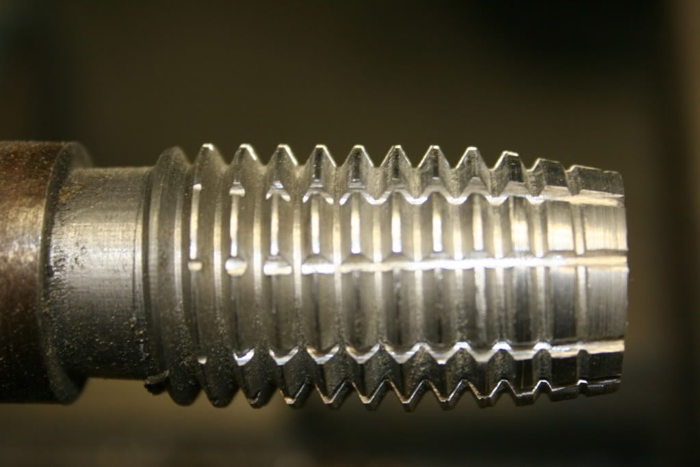
I've decided to try to make a 72 tooth worm wheel. I have made a 7tpi "cutter".

IMG_4345_zps4ac5b94a.jpg


The idea of the cutter design is too rock it back in forth in the lathe while feeding the gear blank into it to the full depth of cut, then rotate the lathe spindle 72 times, probably with a lot of rocking by hand. The gear will be produced in one revolution.

Question of the day: If the depth of cut is .080", what is the proper O.D. of the blank? If I take the reciprocal of 7 times 72, divided by Pi, I get 3.275. Is that the correct diameter, or is it more like the Pitch Diameter?

Bill
 
It appears that for my purposes, the answer is "none of the above". Made a test gear using a scrap piece of aluminum. Made it 2.912", which should have made a 64 tooth gear. Taking an initial cut of .040", I got 66 teeth. Next step, make a blank that is 3.176" and see if I get 72 teeth.

Bill
 
Perhaps you should also consider what sorts of dividing you will be doing, and what plates you are going to use. Higher ratios give greater division combinations per circle, but at the expense of a lot of cranking. Also, there are lots of pre-made dividing plates for 1:72, 1:40, or 1:4 dividing heads, should you think accurately drilling hundreds of tapered holes is going to get a tad tedious.
 

Latest posts

Back
Top