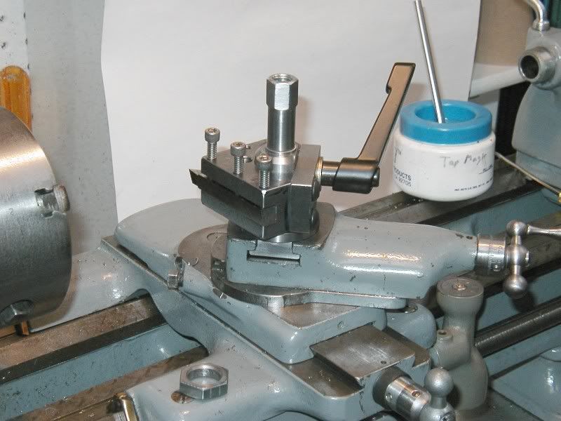
QCTP for Myford lathe

Home Model Engine Machinist Forum

Help Support Home Model Engine Machinist Forum:

This site may earn a commission from merchant affiliate links, including eBay, Amazon, and others.
I am also working on the design of a control box for my Myford. One difference I am proposing for mine is a jog button rather than a switch. This will not have a latching relay, so the motor will only run while the button is pressed. The VFD needs a run signal as well, so it will have double pole contacts.

Hi Charles, Moshe,

I was under the impression that these VFD's would allow the motor to be almost stopped.
 
Yes, my intention is to use jog for very low speed rotation for clocking work true, either in the 4-jaw, or my 3-jaw Griptru. For threading I think I would just turn the speed down with the pot knob (having also put the lathe in bottom direct speed). Don't forget that at low speed you also get low power.
 
Hi Guys,
I did some more on my QCTP today.

After the gear problems with the mill, I got around to starting on one of the tool holders. Got the dovetail machined and started cutting the slot for the tool bits to go into. I decided on being able to use 1/2" square bits. I also slit the main block with a 1mm wide slitting saw. I purchased a 1mm x 150mm saw to do this job. All I have to do now is to drill and tap the five M6 holes for the clamping and the adjusting screw.

Oh :wall::wall::wall:

Forgot to include Pics. Sorry.

QCTP-a01.jpg


QCTP-a02.jpg


QCTP-a03.jpg


QCTP-a04.jpg


QCTP-a05.jpg


QCTP-a06.jpg


QCTP-a07.jpg


QCTP-a08.jpg


QCTP-a09.jpg


QCTP-a10.jpg


QCTP-a11.jpg


QCTP-a12.jpg


QCTP-a13.jpg
 
Hi Baron,


Superp Workmanship.th_wav
I have two DIY QCTP and all done in a hurry and none looked as good as yours in finishing.:hDe::wall:
Would like to make another like yours but it will be for display.
 
Last edited:
Hi Baron,

Superp Workmanship.th_wav
I have two DIY QCTP and all done in a hurry and none looked as good as yours in finishing.:hDe::wall:
Would like to make another like yours but it will for display.

Hi Gus,
Thanks for the compliments. :D:D:D
But you might not think the tool holder is quite as nice. You can see, on the right hand side, of the dovetail. I loosened the quill without thinking and then tightened it back up when I realised what I had done. The net result was that the cutter moved very slightly.

I've another three to make... I promise to try harder. :):):)

Pics attached.

PS. I've yet to knurl the hight adjusting knob and make the lock nut. The hex one you see is only a temporary measure.

CQTP-a14.jpg


QCTP_a15.jpg


QCTP-a16.jpg
 
I've yet to knurl the hight adjusting knob and make the lock nut. The hex one you see is only a temporary measure.
When I made my tool holders I used commercial thumb nuts.


1PU52_AS01.JPG


The other thought is you may have a hard time knuring that part. When machining a part like that I knurl the part while it is attached to the parent metal.
I also recommend a scissors knurl for home hobby machines.
Tin
 
Hi Tin,

Yes I agree I should have left it attached to the bit of bar ready for knurling. :wall:

Unfortunately I took my bump knurler to bits so I could reuse the knurling wheels for the clamp/scissor knurler that I have yet to make.

The hight adjusting screw is M5, and I don't know if there are such thumb nuts available this side of the pond.


I built this for my SB-9 a few years ago and I am delighted with it.

Advantages/features:

Rock solid - tool holder and post lock together like a single, solid piece of steel.
Reposition accuracy - 0.001" or better.
Fast, ONE HAND tool change.
Independent adjustments
Yes, there is a height adjustment screw
Easy to machine - no dovetails

Here is a link to the latest version of the construction article:

http://finance.groups.yahoo.com/group/southbendlathe2/files/7._Project_Files/QC Tool Post/

That looks good. I like the "No Dovetails" to machine bit :)

By the way your link doesn't work for me.:(
 
That looks good. I like the "No Dovetails" to machine bit :)

By the way your link doesn't work for me.:(

You may have to join the group to get to the link.

If you want me to send a copy of the article, PM me with your e-mail address.

Paul A.
 
Just got around to making a slotting attachment to fit the QCTP. Should be much better than winding the lathe saddle back and forth.

I could have done with this when making the new gears for the mill.

Hand_Slotter-01.jpg


Hand_Slotter-05.jpg
 
A few more pictures of my hand slotter.

13062014-016.jpg

The picture shows the handle assembly. Two pieces of 6 mm thick plate 12 mm wide drilled to take 6 mm pins used as pivots. I rounded the ends with a file and made elongated the slot by using two drilled holes and filing the middle bit out.

13062014-015.jpg

The pin that pushes the ram is 6 mm as well and is secured by a 2BA hex grub screw bearing on a flat filed on the pin. The pins were hardened by heating to cherry red and dunked in oil. Though it probably isn't necessary.

13062014-014.jpg

The handle is a length of 13 mm diameter silver steel that someone at some time had heat shrunk a handle on one end. Its just drilled and threaded M5 with nuts on the other side securing the other half.

13062014-013.jpg

I used a 12 mm long piece of 12 mm silver steel drilled 6 mm as a spacer and to keep the handle side plates square.

13062014-012.jpg

This picture shows the tool holder with the ram and operating lever attached.

I've some more work to do on the side plates and top plate.

More later.
 
Hi Gus, Guys,

Well I finished my hand slotter ! I got the thrust screws fitted and adjusted for minimal play in the ram. I can't feel any play in any direction at all. However there is enough side play to cause the "Spot On" to register a single division if I extend the ram to its full extent.

19062014-01.jpg

19062014-02.jpg

A couple of views of the tool laid on the garden table.

19062014-03.jpg

A close up of the top of the slotter showing the two brass screws and lock nuts used for adjusting the play on the ram.

19062014-04.jpg

In this picture you can see the brass runner strip under the ram and the top with the adjustment screws in it.

19062014-05.jpg

19062014-06.jpg

19062014-07.jpg

A few close up's of the top.

All that is needed now is to try it out.

Thanks for looking.
 
Hi Guys,

Just a few pictures of my hand slotter in action. Its attached to the QCTP on the Myford lathe top slide.

26062014-01.jpg

I am using it to put a 4 mm wide keyway slot into a brass bush that supports the gear used on my mill table leadscrew.

26062014-02.jpg

This is a close up of the tool holder attached to the slotter ram. The Allen screwdriver is used to adjust the amount of cut depth by pushing the tool bit outwards. The tool bit is a 60 mm length of 4 mm square HSS tool steel.

26062014-03.jpg

In this picture the tool holder is fully inserted into the work piece. At this point I had cut about a millimetre deep into the bush. I applied a drop of oil to lubricate the tool holder inside the bush.

26062014-05.jpg

Here you can just see the tool bit protruding below the holder. I deliberately set it this way so that the swarf would fall out and not stay in the work where it could jam the tool bit.

26062014-07.jpg

This is a close up of the finished keyway. The marks are where I used a fine file to remove the burr on the edges of the slot.

26062014-09.jpg

And the bush waiting to have the gear, just visible above, fastened to it.

Thanks for looking.
 
I have received several complaints that the link that I posted below does not work. I checked and Yep, it doesn't. It used to. I can only say that the moderators/owners of that Yahoo group have been known to reorganize the files section and when they do this, the old links are rendered invalid. It does not help to complain. It is also hard to find the older files after one of these reorganizations. I have e-mailed the plans to most of those who complained and the remaining one will get them when I have an e-mail address for him.

Anyway, I started a Yahoo group that I own so I can try to organize the files from scratch and hopefully they will not be rearranged. At least, not by me. Here is the link to the posting in the files section there.

https://groups.yahoo.com/neo/groups/MachiningTips/files/Lathe Accessories/

I am also trying to establish my own web site, but time is precious.

I will check this immediately and make any revisions needed for it to work. If you have any questions on this, please do PM me. I will attempt to answer as fast as possible. And if you build my post, I would greatly enjoy hearing about it.

Paul A.


I built this for my SB-9 a few years ago and I am delighted with it.

Advantages/features:

Rock solid - tool holder and post lock together like a single, solid piece of steel.
Reposition accuracy - 0.001" or better.
Fast, ONE HAND tool change.
Independent adjustments
Yes, there is a height adjustment screw
Easy to machine - no dovetails

Here is a link to the latest version of the construction article:

http://finance.groups.yahoo.com/group/southbendlathe2/files/7._Project_Files/QC Tool Post/
 

Latest posts

Back
Top