Potty Popcorn Engine

Home Model Engine Machinist Forum

Help Support Home Model Engine Machinist Forum:

This site may earn a commission from merchant affiliate links, including eBay, Amazon, and others.
Stew,

You forgot to mention that big bits are still falling off the rail bridge due to stress and corrosion, rivets and bolts popping etc, to such an extent, the houses underneath have nets above them to catch it all, but it is still considered safe enough, because of gross over engineering in the first place.


John
 
Bogstandard said:
Stew,

You forgot to mention that big bits are still falling off the rail bridge due to stress and corrosion, rivets and bolts popping etc, to such an extent, the houses underneath have nets above them to catch it all, but it is still considered safe enough, because of gross over engineering in the first place.


John

Hi John

They've stripping the many, many, tonns of old red led paint off it, people were speculating that it was the paint that was keeping it together, :big: its now got a new paint job, that they recon will last for 50 years, for the first time in it's life its not beging painted.

For me it just looks the job.

As an aside my sons father inlaw is a cival engineer and as a young student he walked over the road bridge on the suspension wires, rather him than me.

Stew


Stew---You are doing lovely work there. When I pulled my Popcorn engine apart to install some teflon packing in the glands, I found that when I went to reassemble it there was a bind. I ended up installing a washer about .035" thick between the crosshead guide and the bearing support column. This seemed to free things up considerably. The 3D cad model tells me the washer/spacer is not required, so I can only assume it reflects more on my machining accuracy than on the plans.
 
Thanks Brian

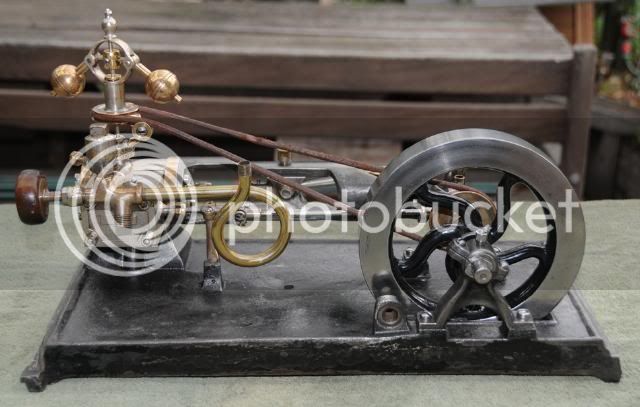
They don't seem to like any tight spots, in fact I'm a little woried that it won't have enough humph to drive the governor, and I've got a hankering to add a clown turning a crank. The only thing to do is try it and see what happens, if nothing else it will look the part. :big:

I didn't get anything done today.

But thought I would ask a ? of you guys, I may have asked it before but no harm in asking again.

I've been trying to get my head round the plumbing you see on popcorn engines, no two seem the same, some look like Russian spy trawlers they've got things sticking out every ware.

I'm going to keep it simple along the lines of this.

Dunbar2.jpg


but without the twirly whirly bit which i've worked out is for a pressure gauge.

But the lubricators the sticky up thing in front of the steam chest looks all wrong to me, its bottom looks to feed into the the steam pipe, but for a displacement lubricator this is wrong.

Has any one got any knowledge of this or access to an engine with a lubricator on they can check out.

Even though I will be running my engine on air and displacement lubricators don't run on air I like the idea of fitting one.

Cheers

Stew
 
Hi Stew,

It's been years since I saw the one I worked on....those grey cells are history.

I would bet that once the engine is divorced from it's cart...the plumbing went with the whim of the engine owner....So I wouldn't get to hung up on it....unless you can find a picture of an original, do what makes sense.

Dave
 
steamer said:
Hi Stew,

It's been years since I saw the one I worked on....those grey cells are history.

I would bet that once the engine is divorced from it's cart...the plumbing went with the whim of the engine owner....So I wouldn't get to hung up on it....unless you can find a picture of an original, do what makes sense.

Dave

Thats good advice Dave,

Its bin suggested on another site that they had a tube coming up the inside to the oil level.

As I will only run with air I'll just make a plain lubricator with an air tight lid, so when i want to oil the cylinder i'll just undo the lid and put a few drops of oil in.

Thanks

Stew

 
That lubricator looks like a graphite pot, but it would seem unclear as to how that valve is constructed. If the pot is placed after the throttle/stop valve, that would make sense as you close the throttle, open the top of the graphite pot, add some, close the cover and when you open the throttle/stop valve it would rush into the engine....the vast majority of which would blow out the exhaust and onto the ground...but at least it wasn't on the popcorn! :big:

I don't think these engines worked real hard but were a novelty.....so that method would work.....steam engines don't hold grudges and put up with all kinds of insults and keep going.

Dave
 
Hi Stew, you are having the same problem I was having when I built the oscy version of the Cretors as a gift to my Dad. I fin ally wound up very loosely following the plumbing layout of an engine that was on display at the Museum of Science and Industry and moved on. It was not "original" to scale by any means but it served it's purpose and I have yet to have anyone comment on the fact. Here is a drawing of a lubricator I found in an old Model Engineering magazine and it reminds me of the lubricator you are pondering. Maybe this will shed a bit of light on an internal scheme.

BC1
Jim

View attachment upright lubricator.pdf
 
Hi Jim

That drawing is just the ticket, much apreciated.

Thanks

Stew
 
YUP pretty basic displacement lubricator....

Dave
 
Ok that one ? answered, now for another


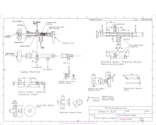
Is their anything worse than a good dose of man flue?:- it,s hit me with a vengeance, so I've cozied up all day in front of the computer, drawing up the supply manifold.

Sht8-Model.jpg


Stew
 
Dragged myself into the shop today and finished off the bits and bobs for the governor:-

Turned up the jocky wheels and crank shaft pully. No pics

Then made the fly ball arms, I used mild steel

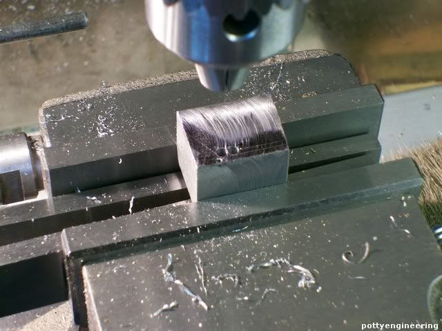
Squared up a block and first drilled the pivot hole 1mm and the corner holes.

131_0983.jpg


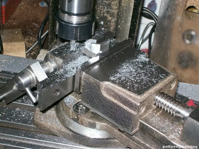
Then with a milling cutter milled one side deep enough to make the two arms, then swiveled the vice round, and milled the angled bit.

131_0987.jpg


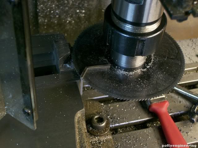
Then split them off with a slitting saw.

131_0997.jpg


Spent a little time filing them to fit, and filed the end into a rough round then run a M2 die down it.

Drilled and tapped the balls

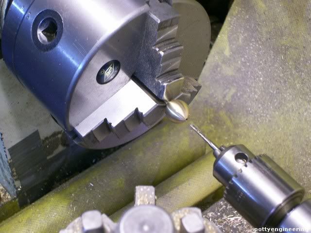
131_0999.jpg


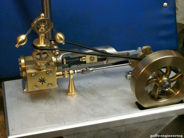
I took delivery of some 3mm dia o ring cord this morning that I'm going to use for the drive belt, so time for another hows it going to look shot.

131_1001.jpg


Stew
 
Thanks:- Dave/Saw/Bernd

Ok with my bigger watermark now in place.

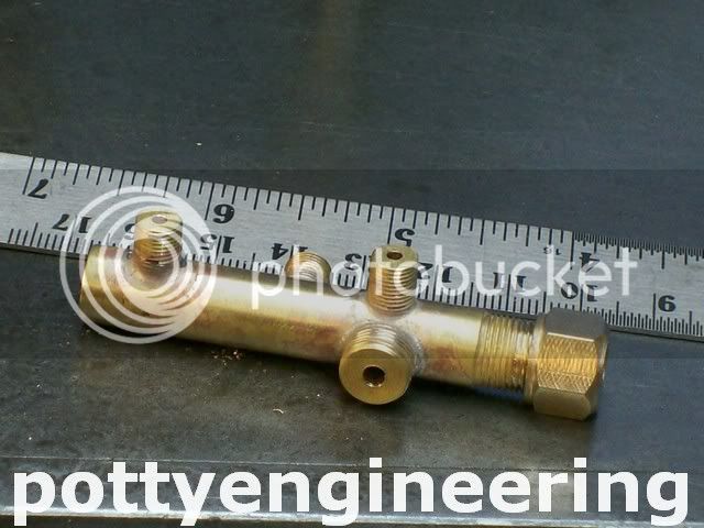
Made the manifold.

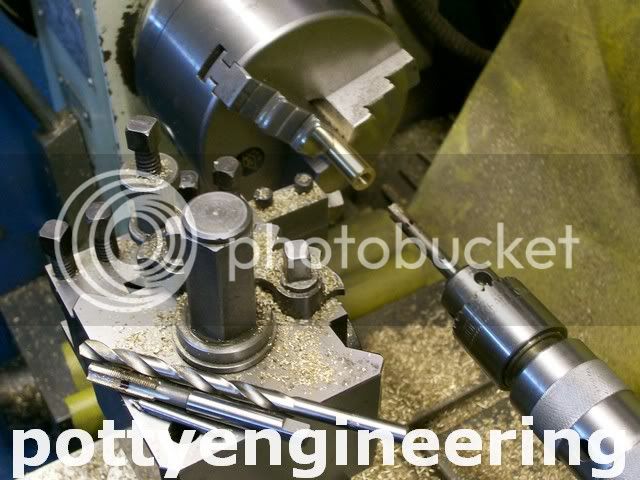
Started with a bit of brass bar, turn it down to size and part off.

131_1006.jpg


Then drill and tap one end marked the tap up so i wouldn't go in too deep.

131_1007.jpg


Turned it round and did the same to the other end and also thread the OD 3/8*32 ME.

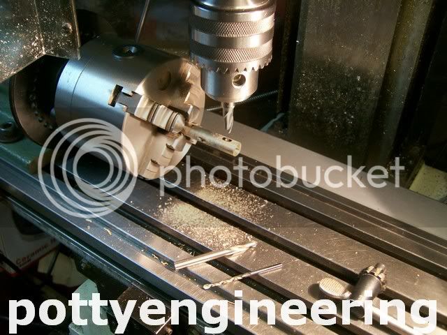
Then mark out where the holes are to go, then in the spin-indexer drill the holes 3mm for the couplings, also milled a small flat on the hole position so the coupling would have something to sit square against for soldering.

131_1011.jpg


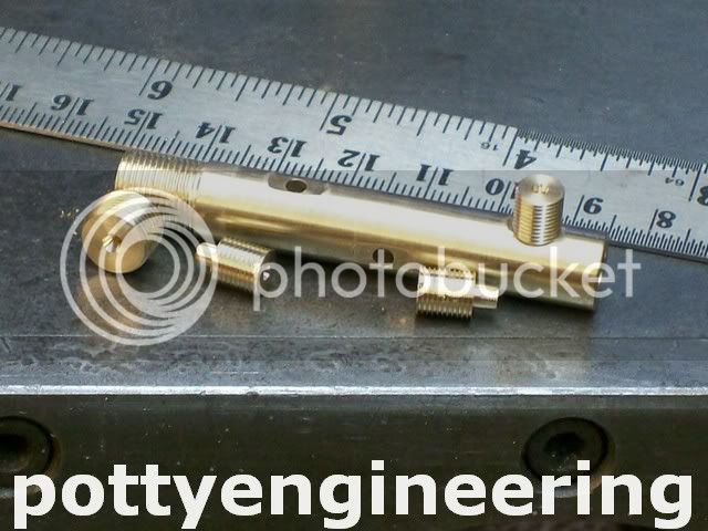
Turned up the coupling with a little 3mm nipple on the end 3mm for a tight fit in the manifold.

131_1013.jpg


Couplings pressed in.

131_1014.jpg


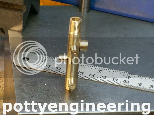
Onto the silver soldering just added a little bit of flux, and a few nuggets of solder and heated them up to everything melted in, then into the pickle for 1/2 hr.

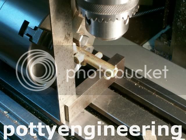
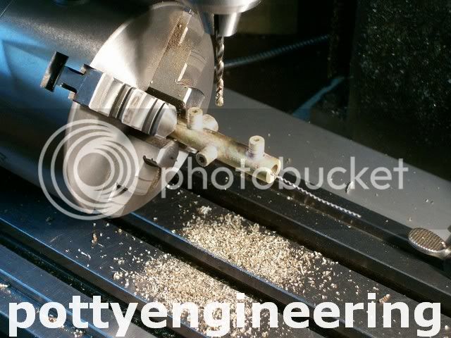
Back onto the spinindexer, square up onto one of the coupling pick the hole centres up and drill.

131_1015.jpg


131_1016.jpg


Wilst it was in the pickle made the stop valve nut.

Her it all is

131_1019.jpg


Stew
 
Stew,

If I could suggest something with reference to your watermark.

Leave it the same size but relocate it into the centre and reduce the opacity to something between 5 & 10%.

It will fade into the background and not interrupt the viewing of the picture but it will still be well watermarked. As it is, it could distract from the actual picture or cover something up of interest.

John
 
Finished off most of the fittings for the manifold.

To make the body for the whistle valve just square up a chunk of brass and put a small centre where the coupling will be turned.

IMG_3527.jpg


Then using the good old wobble bar get it on centre in the four jaw chuck

Turn and thread 1/4*40 and drill through 2mm and part off

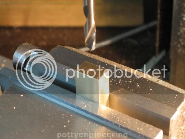
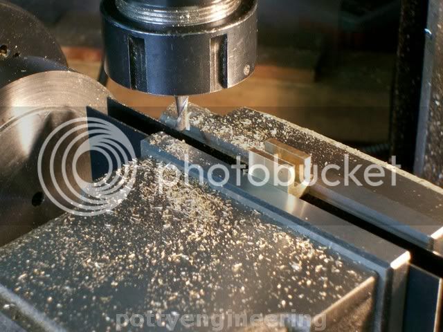
Over onto the mill and mill a 3/16 slot across it.

131_1028.jpg


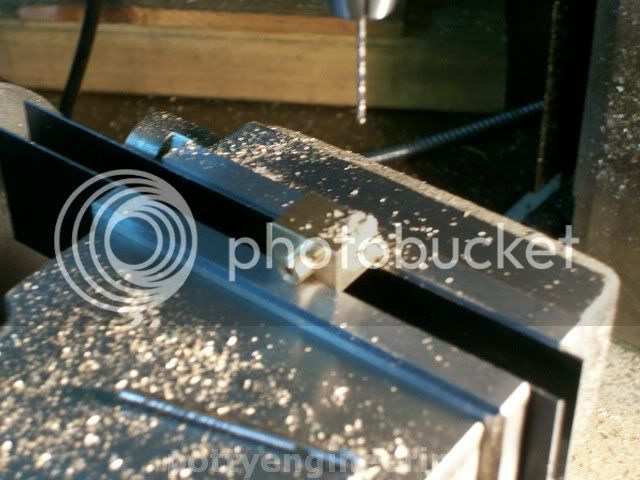
Drill a 1mm hole for the lever pin

131_1030.jpg


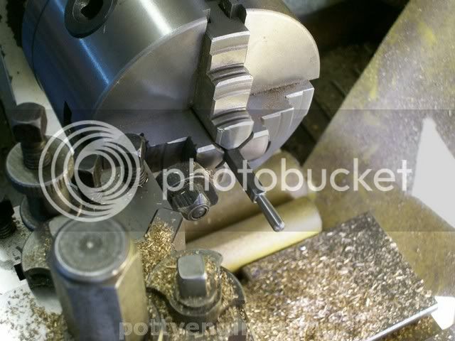
The lever is made from some 3/16 square mild steel bar, so in the self centering four jaw with the compound slewed over a couple of degrees turn up a nice shaped handle, and part off.

131_1031.jpg


Drill a 1mm hole for the pivot pin.

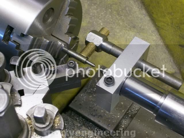
Next bit the valve spindle, from a bit of 8mm dia stainless, centre drill and with a running centre turn and thread.

131_1034.jpg


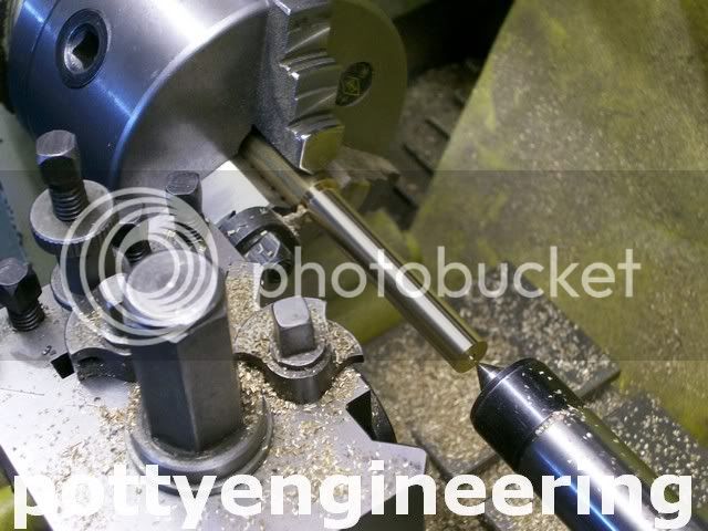
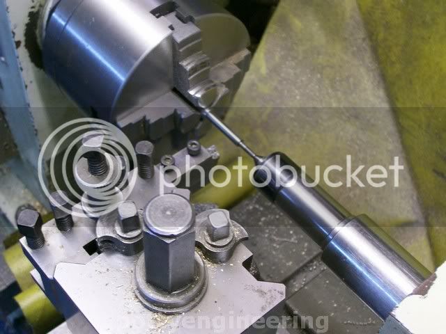
Flip it round and turn and thread the other end again using a running centre, to turn the cone I used a small fixed steady that I made some time ago it just clamps on the running centre.

131_1035.jpg


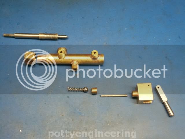
These are the bits

131_1043.jpg


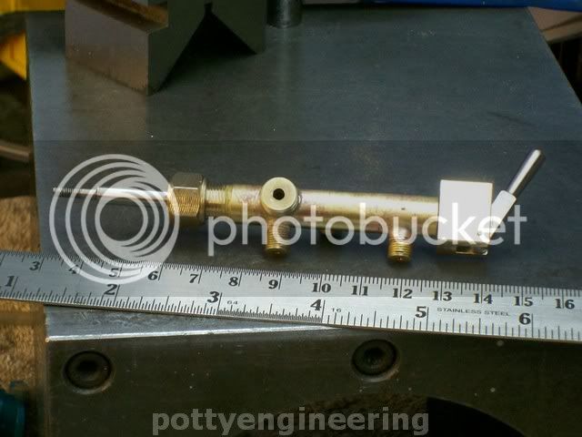
and assembled

131_1038.jpg


Cheers

Stew


Stew

Thank for showing this in detail. Engineering is so much more than engines and this is an excellent example of attention to detail. I need to learn a lot more about piping and valves.

Jerry
 
stew it is really looking good looks like i need to get busy to get mine done. nice work and detail. jonesie
 
Love the steady rest....it is so much better for small parts than the conventional ones!

Dave


Latest posts

Back
Top