You are using an out of date browser. It may not display this or other websites correctly.
You should upgrade or use an alternative browser.
You should upgrade or use an alternative browser.
PM Research No. 1 Build
- Thread starter rhitee93
- Start date

Help Support Home Model Engine Machinist Forum:
This site may earn a commission from merchant affiliate
links, including eBay, Amazon, and others.
- Joined
- Oct 29, 2011
- Messages
- 284
- Reaction score
- 2
rhitee93 said:It is funny you mention that because I am struggling with this idea. I want to round over the top edge a bit, however I know that in the real world, the round edge was supposed to be on the bottom and the flat side was up.
Wait, what? Have I been putting nuts on the wrong way around all this time? The only online discussion I could find was http://powerlineman.com/lforum/archive/index.php/t-7628.html, which has all kinds of opinions
Simon
- Joined
- Jun 4, 2008
- Messages
- 3,294
- Reaction score
- 636
I've been using the scale nuts from AME. Not as thick as yours though, but they do have the rounded edges.
mklotz
Well-Known Member
For model nuts, I use...
D = major bolt diameter
1.5*D = across flats nut size
0.9*D = nut thickness
I've always mounted nuts with the chamfer/rounded side up. I'll be interested to hear an argument for inverting that choice.
D = major bolt diameter
1.5*D = across flats nut size
0.9*D = nut thickness
I've always mounted nuts with the chamfer/rounded side up. I'll be interested to hear an argument for inverting that choice.
- Joined
- Mar 13, 2012
- Messages
- 583
- Reaction score
- 62
Perhaps I am wrong about the nuts.
In my circles, conventional wisdom with hardware on antique machinery is that nuts that have a chamfer on only one side are installed chamfer side down so that the corners on the flat side don't scar the mating surface for the nut.
I can't say that I have ever heard an authority on the subject.
In my circles, conventional wisdom with hardware on antique machinery is that nuts that have a chamfer on only one side are installed chamfer side down so that the corners on the flat side don't scar the mating surface for the nut.
I can't say that I have ever heard an authority on the subject.
mklotz
Well-Known Member
Your argument makes sense. Modern commercial nuts are often chamfered on both sides. If the chamfer is there for your purpose, as opposed to just making them burr-free, then it would be logical to chamfer both sides so the operator can't get it wrong.

$99.99
AHS Outdoor Wood Boiler Yearly Maintenance Kit with Water Treatment - ProTech 300 & Test Kit
Alternative Heating & Supplies

$19.15
$29.95
Competition Engine Building: Advanced Engine Design and Assembly Techniques (Pro Series)
MBC Inc.

$45.99
Sunnytech Mini Hot Air Stirling Engine Motor Model Educational Toy Kits Electricity HA001
stirlingtechonline

$36.94
$49.99
Becker CAD 12 3D - professional CAD software for 2D + 3D design and modelling - for 3 PCs - 100% compatible with AutoCAD
momox Shop

$26.89
$34.99
Peachtree Woodworking Supply Bowl Sander Tool Kit w/Dual Bearing Head & Hardwood Handle, 42 Pieces Wood Sander Set, 2 Hook & Loop Sanding Disc Sandpaper Assortment, 1/4 Mandrel Bowl Sander
Peachtree Woodworking Supply Inc
![DreamPlan Home Design and Landscaping Software Free for Windows [PC Download]](https://m.media-amazon.com/images/I/51kvZH2dVLL._SL500_.jpg)
$0.00
DreamPlan Home Design and Landscaping Software Free for Windows [PC Download]
Amazon.com Services LLC

$599.00
$649.00
FoxAlien Masuter Pro CNC Router Machine, Upgraded 3-Axis Engraving All-Metal Milling Machine for Wood Acrylic MDF Nylon Carving Cutting
FoxAlien Official

$49.95
$55.99
DjuiinoStar Hot Air Stirling Engine Assembly Kit: Spend 30 Minutes to Build Your Own Stirling Engine
djuiinostar
Maryak
Well-Known Member
- Joined
- Sep 12, 2008
- Messages
- 4,990
- Reaction score
- 77
Nuts.........where to place the chamfer.
My understanding is that a nut with the chamfer on one side, is that the non chamfered side goes against the mating face as an aid to locking when using only a flat washer under the nut. Without a washer it will bite into the parent part but IMHO this still the more correct way to fit such a nut. IIRC the chamfer was originally fitted to facilitate easy engagement of a ring spanner/socket as well as removing unnecessary sharp corners in way exposed edges.
Best Regards
Bob
Don1966
Senior Member
- Joined
- Jan 19, 2012
- Messages
- 487
- Reaction score
- 24
Maryak said:IIRC the chamfer was originally fitted to facilitate easy engagement of a ring spanner/socket as well as removing unnecessary sharp corners in way exposed edges.
Best Regards
Bob
Agree
Don
idahoan
Well-Known Member
- Joined
- Oct 7, 2008
- Messages
- 594
- Reaction score
- 210
I agree with Bob,
This was debated heavily a few years ago on one of the antique engine mailing lists. The majority of the folks agreed the chamfer should face up. This was for square nuts.
But; antique High Crown Hex Nuts and Bolts are a different animal. They have a releaf turned on the bottom to keep the hex points from digging in and the tops of the nuts are chamfered.
The bolts are made two different ways; it seems the on some engines they have a radius on top and on some engines they had the high crown but a flat top with a chamfer.
One of my old engines from the teens has the flat top bolts; Im really not sure why the difference. I have also seen the nuts with a radius instead of the chamfer on some engines.
You can see on my Pacific how I did the main bearing cap nuts; I feel that this is the proper way, releaf on the bottom and chamfer on top.
http://www.homemodelenginemachinist.com/index.php?topic=18682.45
Also I have up loaded a drawing I found on Harrys antique engine (I don think that it is copyrighted) that shows the dimensions for some full sized hardware.
http://www.homemodelenginemachinist.com/index.php?action=tpmod;dl=item405
The Pacific will have the High Crown Bolts with the radius on top because they look proper and are cool.
Dave
- Joined
- Mar 13, 2012
- Messages
- 583
- Reaction score
- 62
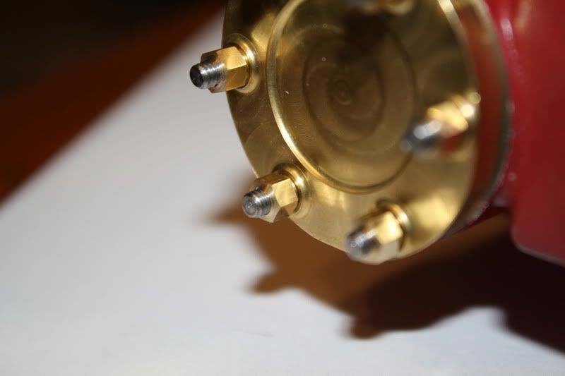
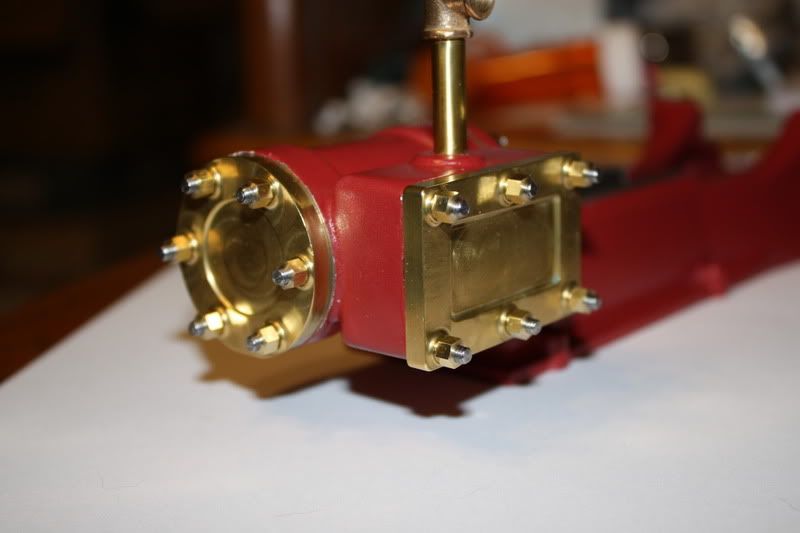
OK, let the great nut debate end  (For this build anyway) I used Dave's approach and rebated the mating side and chamfered the top side. The difference is subtle, and doesn't show up in the photos well. However it does appear more finished now, and I think it was an hour well spent.


The details are important, every edge or face added reflects light in a slightly different way and adds to the richness of the appearance. Seems to me when there is enough detail it starts looking real and a combination of a good paint job and that detail make your engine look just that.
Jan
Jan
Don1966
Senior Member
- Joined
- Jan 19, 2012
- Messages
- 487
- Reaction score
- 24
Hi Brian not trying to rush you, finishing an engine to me is the fun part. It has to be just right, because this is what sets it off from just a raw engine. I am anxious to set it finished. You have done a great job so far.
Don
Don
- Joined
- Mar 13, 2012
- Messages
- 583
- Reaction score
- 62
I'm just teasing you Don. Your attention to polishing the parts on your engines is one of the things that has gotten me to slow down and pay attention to the details. I usually struggle to maintain my patience during the finishing stages of a project.
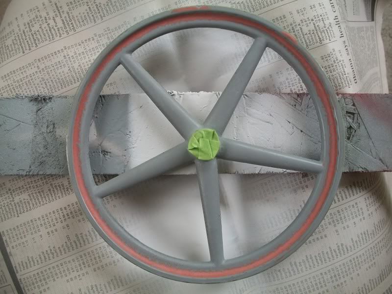
I didn't get much done today, but I did manage to get the flywheel ready for its final coats of paint. The hub and the outside of the rim are taped off, but I left the edges of the rim unmasked. I'll take a cleanup pass on the sides after the color is on. Wet sanding between coats means I have to re-mask each coat, and taping off the edge of the rim was a pain.

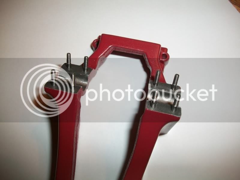
I also got the 3-48 studs made for the main bearing caps. I didn't take any photos since it was basically the same process I used before. Thankfully, the list of hardware I still need to make is starting to get short

I didn't get much done today, but I did manage to get the flywheel ready for its final coats of paint. The hub and the outside of the rim are taped off, but I left the edges of the rim unmasked. I'll take a cleanup pass on the sides after the color is on. Wet sanding between coats means I have to re-mask each coat, and taping off the edge of the rim was a pain.

I also got the 3-48 studs made for the main bearing caps. I didn't take any photos since it was basically the same process I used before. Thankfully, the list of hardware I still need to make is starting to get short

Very nicely done Brian.
But don't go overboard with the flatting down, you have to remember, it is made from castings, and a little bit of that must show, otherwise you may as well have made it from barstock.
It is a very fine line between getting an engine to a highly polished example of a real one, more like a showman's engine, rather than an example of a scaled down version of a full sized working example.
I am just showing my Scott flame licker build, and I can polish and paint that to whatever depths I want to go to, because it isn't a scale model, just a 'looker', but other engines I will be building from castings, you should just be able to detect their casting based origins.
But of course, that is just my personal view. It's your engine, you do whatever you want.
John
Similar threads
- Replies
- 8
- Views
- 1K


