PM Research No. 1 Build

Home Model Engine Machinist Forum

Help Support Home Model Engine Machinist Forum:

This site may earn a commission from merchant affiliate links, including eBay, Amazon, and others.
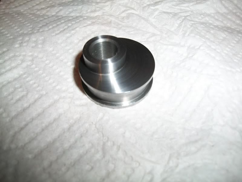
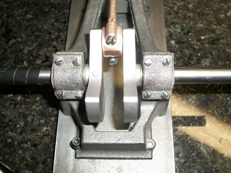
Well, work has been creeping into my private life for the last couple of days, but I took a break tonight and made couple of little parts for the engine. I decided to build up a crank rather than use the cast one that came with the kit. I used 3/8" steel to cut out the webs of the crank because it was a convenient size. However, this meant that I couldn't make the crank wide enough at the journals. I was OK with this since it would allow me to cut a pair of custom spacers to perfectly match the crank to the opening in my frame.

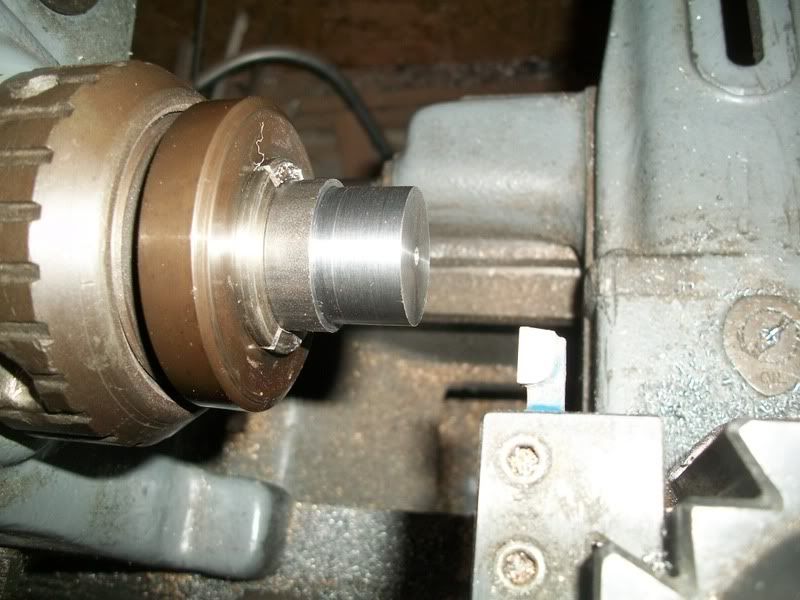
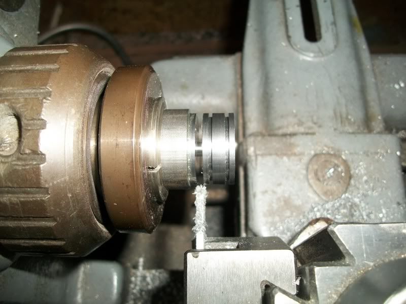
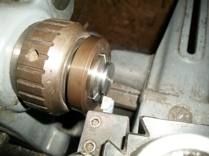
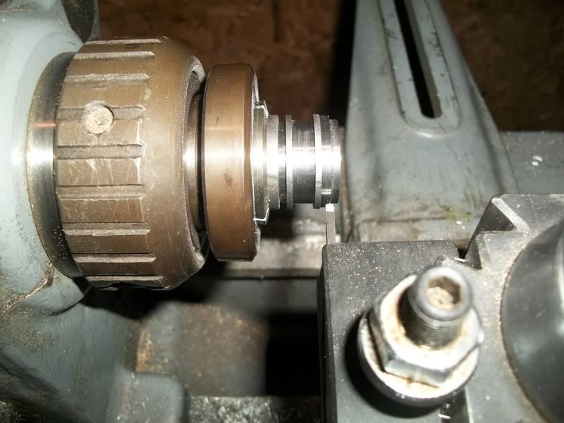
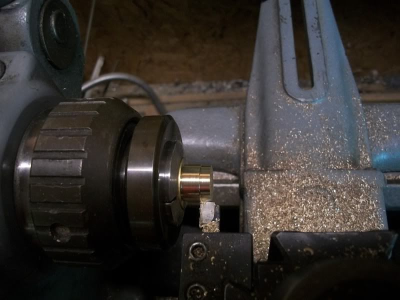
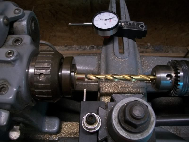
In the first pic I am turning down some brass to size.
100_1872.jpg


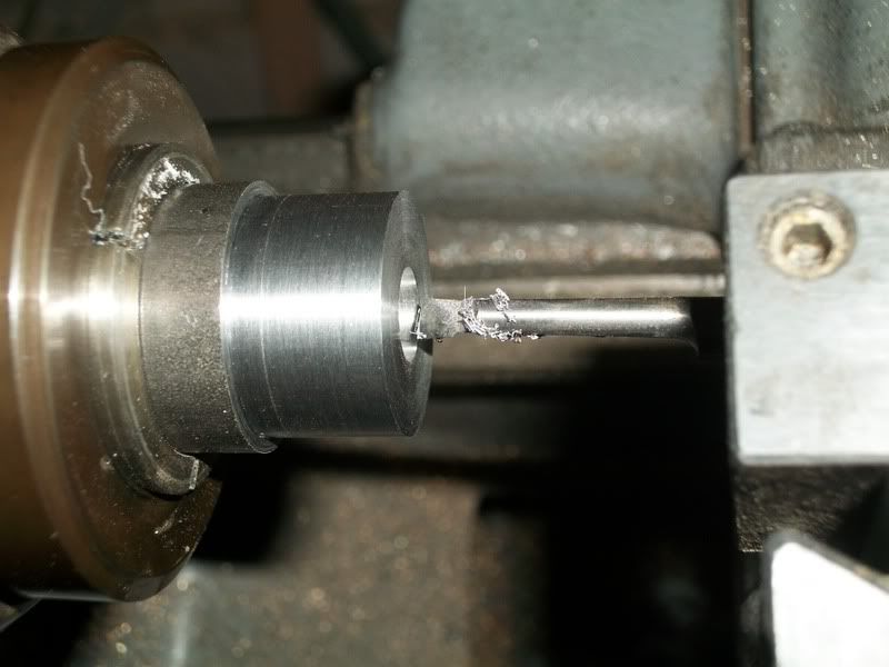
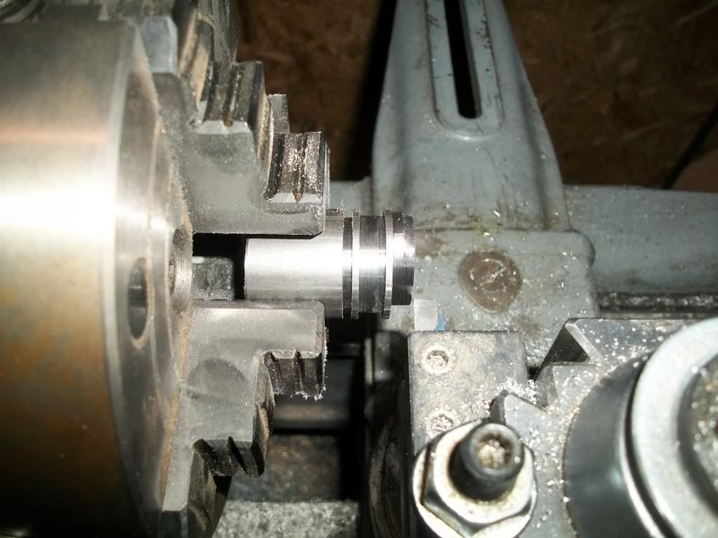
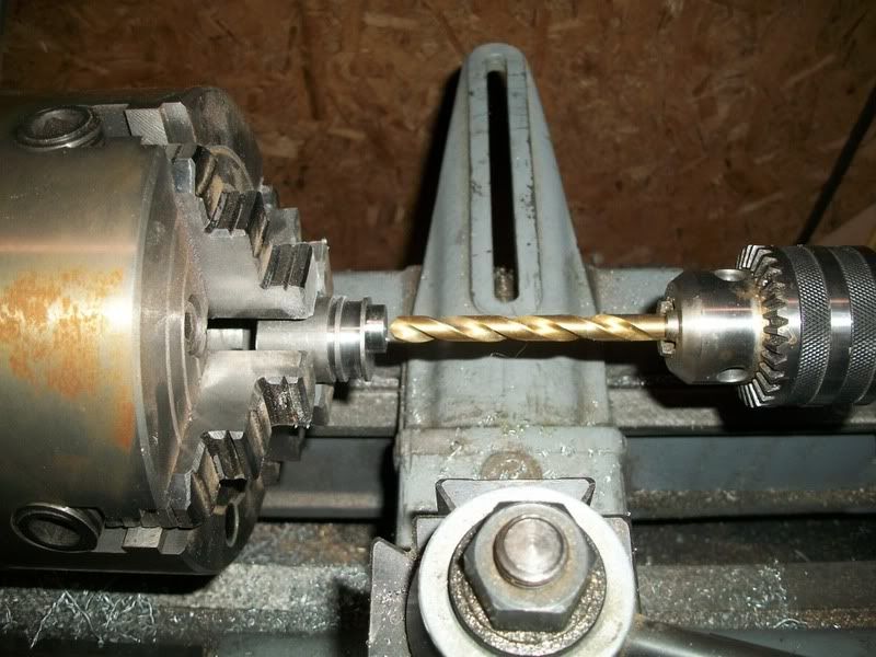
And drilling it out with a 3/8" drill
100_1873.jpg


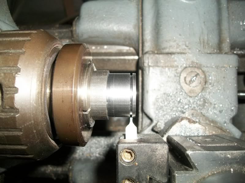
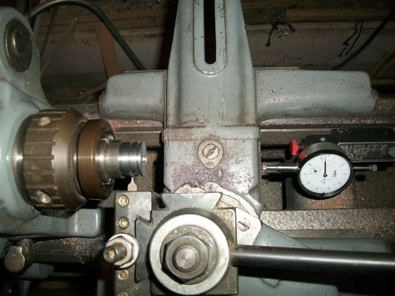
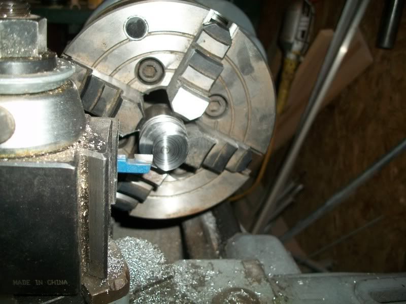
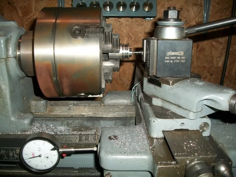
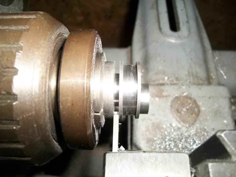
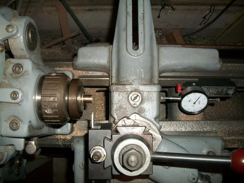
OK, those 2 pics are a waste of bandwidth, but this one might be interesting to some of the less experienced folks. Next I parted off the spacers. I don't have a DRO on the lathe, so I use a dial indicator. I just make a skim pass with the parting tool, and set the dial to 0. Then I move in the width of the tool, and set to 0 again. Then I move over the thickness of the part I want and cut away. Not rocket science, but I find I can make parts within a thou or two this way all night long. (Yeah, I could do it in one move if I trusted myself to add in my head, but I don't)
100_1874.jpg


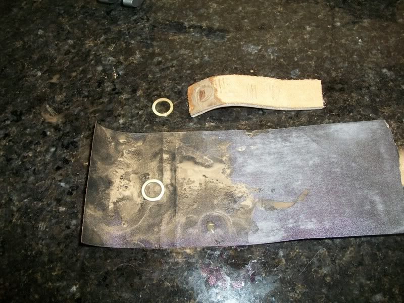
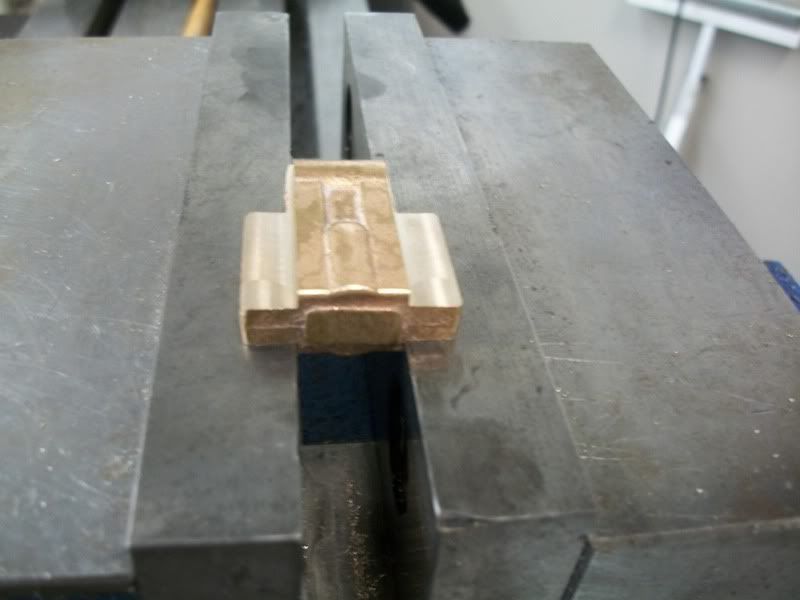
I intended to cut the parts off about a thou over so I could wet sand them to a perfect fit. It turned out I actually made them much larger than necessary and had to spend some time sanding away. After removing my fingerprints, I tried using a piece of leather to hold the spacer down against the sand paper. This worked like a charm, and I wish I had tried it years ago ::)

100_1876.jpg


The piece of granite is a cutout from a counter top that someone gave me. It is handy as all get out.

Here is a shot of the spacers in place :)
100_1879.jpg
 
You are definetly not the only one doing those things. When I do that my wife always gives me that strange look.

Vince
 
Looking great Brian...and thanks for the tip about the leather while sanding....I've lost my fingerprints a few times too and it ain't no fun!! Nice little video too...I think most all of us can relate to that whether we admit it or not...lol.

Bill

 
I got a couple of hours tonight to work on the engine so I decided to get the piston done. First I faced off the slug of CRS that came with the kit, and drilled the .125" through hole. Then came the important part - turning the OD to size.

My cylinder honed out to 1.0035 so I set the target diameter to 1.0025. I know my lathe pretty well, and can usually turn to a target diameter in this size range without a lot of fiddling, but she surprised me tonight. I made my second to last pass expecting to be at 1.0040, and ended up with 1.0015. Oh well, I'll run with it and see what happens. :)

100_1888.jpg


next I bored out he counterbore for the piston rod nut. This little boring bar is one of my favorite tools. I have another one that is about 1/3 this size that I absolutely love as well.

100_1890.jpg


Next it was time for the ring groves. This is a tool that I ground for some other purpose a long time ago. It is ugly as all get out which, unfortunately, is a pretty good description of my tool grinding ability. For whatever reason it cut through this CRS like butter. The tool happens to be 0.043" wide and the groves are supposed to be 0.050" wide so I cut to depth, backed out, stepped over 7 though and plunged again. I didn't want to try to cut sideways with this tool.

100_1891.jpg


Here is a shot of the second grove being cut, and the dial indicator setup I use for operations like this.

100_1892.jpg


This lathe and I usually get along pretty well when it comes to parting, but this was a pretty deep cut so I wasn't too sure how this would end up. I had to stop every 30 thou or so and put a drop of oil on the cutter, but in the end it came out just dandy. Somewhere along the line my parting tool has become magnetized which is a bit annoying. I'll have to fix that one of these days...

100_1896.jpg


Parting didn't leave me with a very nice surface, so I took a very light skim pass.

100_1898.jpg


And finally a test fit with the cylinder. Being a couple thou undersized the fit is quite free, but I thing the rings will make it OK. I made the piton a little longer than the plans say to make up for the fact my cylinder is a bit too long.

I hope to get the crosshead made this weekend!

100_1902.jpg
 
Brian,

I am really glad you have changed over to the embedded pictures, I can now follow along with your build. :bow: :bow: :bow:

It looks like up to now you have solved all your problems, except one. :'(

I am not being critical of your work at all, but of the kit supplier. It seems that PM do this with all their kits, and it really spoils the overall effect of what you are building.

This is a common problem when people first start to build from castings.

If you really want to lift your build to a much higher level, get rid of the crappy screws that the kit manufacturer has supplied, and either make hex headed bolts out of the screws supplied or just buy some to replace the ones you have already fitted or about to fit.

When you buy a casting kit in the UK, rather than spoil a good build with crappy fixings, they are usually supplied with no fixings at all, (or if they do supply, they will usually be the correct ones), leaving the choice to the builder.
It looks like PM are trying to help, but they are doing it on the cheap and making their casting kits look cheap and nasty when finished off, purely because of the general purpose screws they have supplied. :redface2:

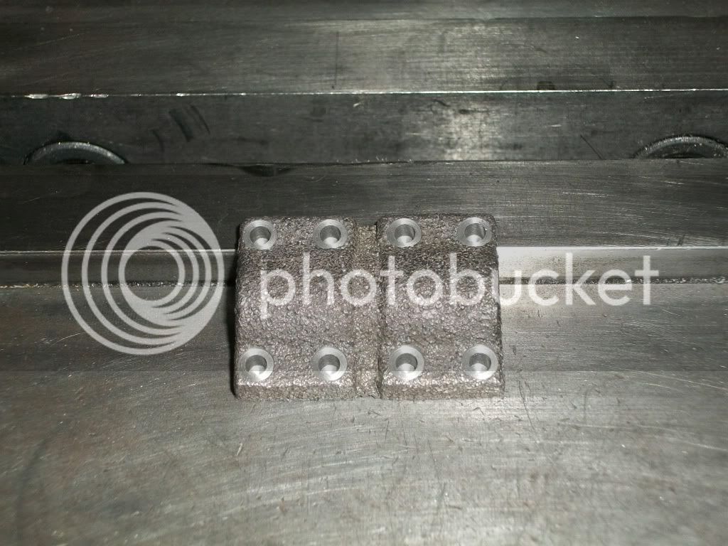
Another point, if you have a bolt tightening down to a face, that face should be machined, not left as cast.
Have a look at your crank bearing caps, if you had just run a cutter across the faces where those screws are, or even spot face where they fit, it would lift the quality of your build no end, and it only takes a couple of minutes to do.

As I said, I am not being critical at all, I'm just trying to help you to achieve a much better looking engine.

John
 
I'm with you on the hardware John. I intend to use something that looks nicer for the final assembly. Since I have opted to use the imperial threads called out in the prints, i think my best option is probably making studs and nuts. That is why I have been so willing to beat up the kit hardware when doing the machining steps and the test fits. True it is cheap hardware that was supplied, but for $112 (71 GBP) I wouldn't expect much more.

Your point about spotfacing the bolt locations if true, but in fairness the plans call this out. You would have to go back through the thumbnails photos to see where I show this, but all of the locations that bear the fastener load are machined.

Thanks for your input. Your attention to detail on your builds that I have gone back an looked at has inspired me to put extra effort into some of the small details on this engine when it comes time to do all the finishing steps.

Holesalmostdone.jpg
 
That looks good so far Brian, and believe me when I say, you won't be disappointed by making up studs instead of cap screws or other fasteners for those bearing caps. The very same holds true on the cylinder head as well. Here are a couple of images to give you a visual of the finished 'look'. The studs are just a bit 'fiddly' to make up and get right but the overall effect just makes a model jump in terms of realism. Well worth the effort and time required. Thanks for sharing your adventures BTW, I'm enjoying it tremendously.

BC1
Jim


PMR#1.JPG


PMR#1a.JPG
 
Thanks Jim. It looks like you made proper scale studs. I have to admit I was just thinking about getting some threaded rod and cutting to length. I'll probably have to make the nuts because the modern nuts with the taper at the edges just wouldn't look right.

I see you are using some fairing compound to smooth out your castings. That is a question I have been struggling with.
 
Hi Brian,

Yes, I went with 'proper' studs as I just get these niggling feelings when I don't, that it just isn't 'right' somehow or that I am cheating by using thread-all in such applications. As for smoothing out the castings, I first went over them with a bit of emery cloth to get the surface knocked down to an overall, even, bumpy surface. I then applied two coats of white metal primer, allowing both to thoroughly dry between coats. Then i applied a somewhat wet coat of grey metal primer and after letting that stand in the sun for a coupe of days, I rubbed the castings down with wet/dry paper to even out the surface. the two colors of primer allows one to actually bear witness to what is happening in terms of material being removed and where. Once all the machine work is completed I will mask off the necessary surfaces, spray on another coat of white and perform the final sanding operations followed up with the color coats and more wet sanding.
You are right about not using standard nuts for our models, the profiles are just wrong and the thicknesses are incorrect as well. Who ever would think that making a model could prove to be so challenging?
I am looking forward to seeing your continued forward progress and am certainly anxious, as I know you are, to see this one run. Keep up the good work.

BC1
Jim
 
Great work Brian, I have to admit I am learning things from your built as well. I am still here following your built keep up the good work.

Don
 
Saturday was one of those days I should have just stayed out of the shop. I had looked forward to getting started on the crosshead for several days, but things kept popping up all day that kept me busy. It was 7:00PM by the time I had time to start working. Then I made one silly little mistake after another. By the time I was done I was pretty convinced that I had messed up the part completely and would have to make another.

However, I made a piston rod, and with some minor adjustment, the whole crank to piston assembly is turning pretty well. I think the crosshead can be saved after all.

I also want to point out that I don’t think I would try this machining sequence again. I had to use too many setups. This part has to be pretty precise to keep things well aligned, and the integration error caused by all the setups adds up quickly. I don’t have a better suggestion, but I wouldn’t recommend the way I did it.

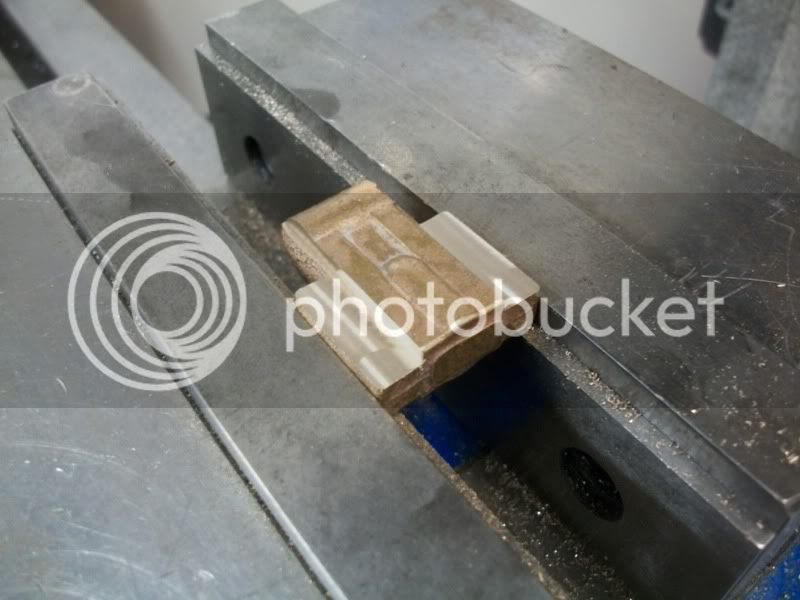
First I started machining the horizontal bearing surfaces. I took just under half of the required material off one side while the other side was resting on parallels.

100_1907.jpg


Then I flipped the part over so that the freshly machined face was resting on the top of the vise jaws. I set the z-axis zero to the top of the vise jaws, and then cut to the finished thickness. (I left a thou on each face for cleanup)

100_1910.jpg


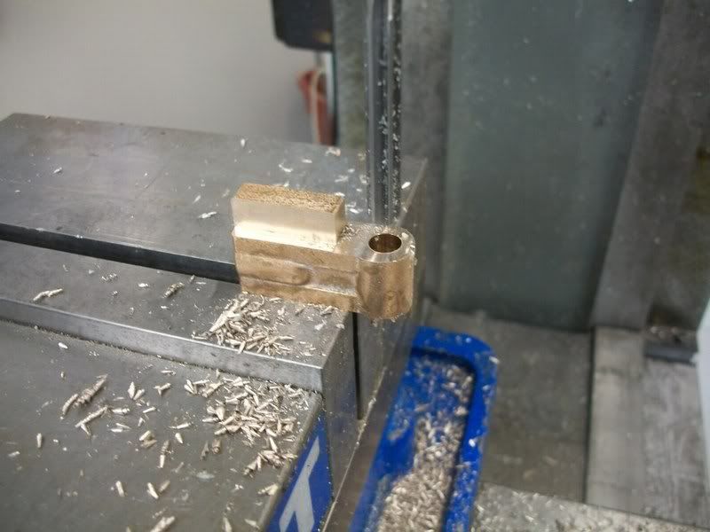
Next I flipped the part around, cleaned up the sides of the wrist pin location and drilled/reamed the hole.

100_1911.jpg


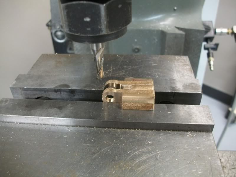
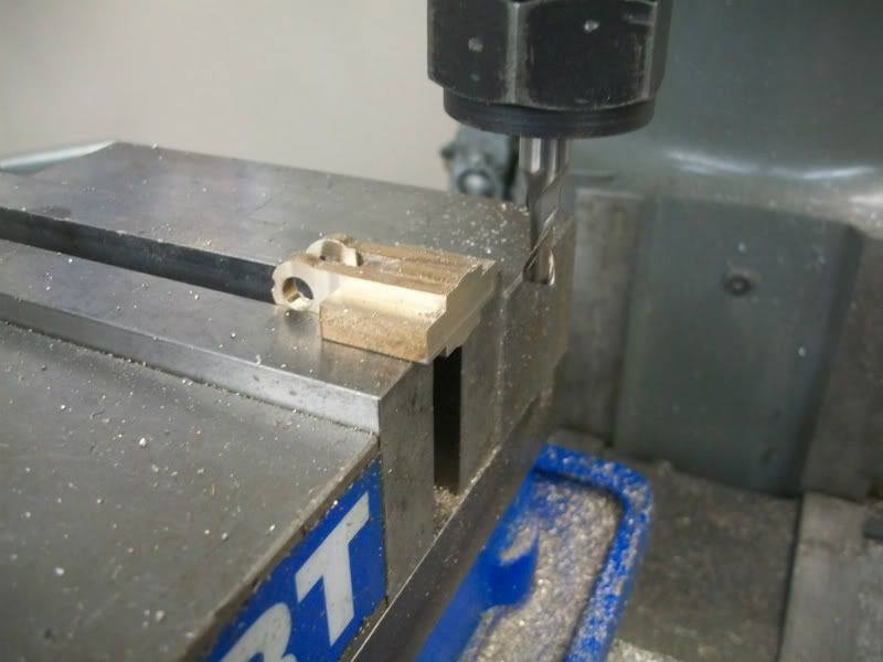
Then I moved the part back over and cut the slot for the small end of the connecting rod.

100_1912.jpg


Then I faced off the end for the piston rod. I could have avoided this setup if I had been thinking clearly when I positioned the part for the last operation.

100_1913.jpg


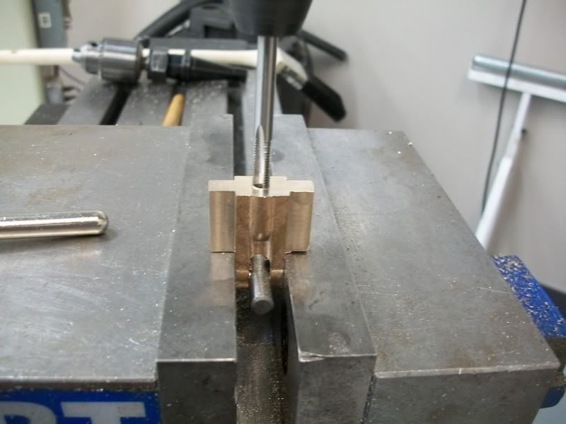
Then I moved the part one last time to drill & tap the piston rod hole. Notice the drill shank being used to keep from distorting the connecting rod slot.

I’ll try to get another quick video of the engine moving. When my timing is right, I can keep it turning by simply pushing on the outboard side of the piston.

100_1916.jpg
 
Here is a silly video of me playing the part of the boiler. :)
(Sorry for the gross waste of bandwidth, but I have the imagination of a 5-year old)

[ame]http://www.youtube.com/watch?v=XANvn27sjrs[/ame]
 
That is sweet Brian!!!

A few more parts and you will be done!
Love the video!!!

Andrew
 
I was dog tired when I got home from work tonight, and had written off any shop time. However after a quick nap I though I would get a start on the eccentric hub. The next thing I knew it was 10:00, but I had the part done. (Well almost done)

I started by putting the piece of 1.125" CRS from the kit in a collet and making a cut to define the outboard side of the eccentric. I would come back and part the piece off at this location later, but for now if serves as a well defined zero location. I set my dial indicator to zero and stepped over the thickness of the parting tool and the thickness of the "Rim" the keeps the eccentric in place.

100_1923.jpg


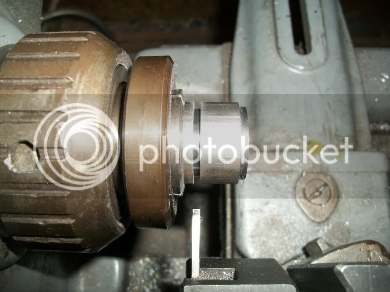
Then I cut out the section that the eccentric will ride on. I plunged most of it out with the parting tool and cleaned up the surface with some very light passes side to side. You are not supposed to do that, but I think everybody does...

100_1926.jpg


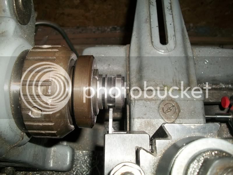
Next I stepped over the right amount to define the other "Rim" of the hub. I'm not sure why I did it this way, but it seemed like the right thing to do at the time.

100_1927.jpg


Then I put the part in my 4-jaw and centered it up. Then I offset it the 0.188" called for in the prints. After doing that I realized that all I had to do originally was get the part to where it had a TIR of 0.376", and that I could have skipped the centering step. Oh well, live and learn. This is only the 2nd time I have ever turned anything off center this way. Oh, yeah, I still need to clean the rust off my 4-jaw :-[

100_1928.jpg


I don't like interrupted cuts like this, and was only taking 10 thou of at a time. However, lots of handle turning later and I was making progress.

100_1929.jpg


Once I finished the hub for the eccentric hub (The hub-hub :) ) I centerdrilled and drilled to 11/32".

100_1931.jpg


Then bored to a nice fit on my crankshaft material. I could have just reamed it, but I enjoy boring on a lathe so I tend to favor it. This was a blind hole, so the dial indicator told me when to stop.

100_1932.jpg


I had left the hub-hub a little too long so I faced it off and added a bit of a chamfer. Then it was time to part it off so back to the collet it went.

100_1938.jpg


After a little time with some wet/dry paper to smooth out the flat side, here is the part. I still need to drill and tap the grub screw hole, but that can wait for tomorrow.

100_1939.jpg


I enjoyed the video, anytime I have two parts that go together they get assembled and played with. :) Your explaining how to make an eccentric is handy as I need to make one soon. Boring is one of my favourites too, I only ream up to 6mm, after that I bore.

Jan
 
hi Brian, did you have any problem when you were taking the final parting cut due to the off center hole????

the first time i made one(ive only really made one... haha) when i was doing the same final parting, when i reached the hole the tool grabbed and all manor of unpleasant things happened. was there anything you did during this step differently to a standard plunge cut/parting off without an off-center hole??

cheers Mackye
 
Mackye,

I was worried about the effect of the off-center hole when I parted the piece off, but I think it actually helped clear the chips. This is the same piece of stock I made the piston from, and I had to go a lot slower when parting it off than I did here.

This lathe always does well when parting. It weighs in at 1100 pounds so there is some mass there to hold everything in place. I don't know much about tool grinding, but the way I grind my parting tool may have some effect as well. I always put a little hollow grind on the top side just behind the cutting edge. I think the proper term is that I have a lot of rake angle? I can take a pic if it would be helpful...
 
H Rhitee,

Your doing a great job there. Thm: Wish I could do similar.


rhitee93 said:
I can take a pic if it would be helpful...

Please do. :)
 
Great progress and great pictures Brian. Loved the short video too...a new take on the finger engine perhaps ??? Seriously though, it really is coming together nicely and should make a beautiful model!!!

Bill
 

Latest posts

Back
Top