Plunket Jr. Build

Home Model Engine Machinist Forum

Help Support Home Model Engine Machinist Forum:

This site may earn a commission from merchant affiliate links, including eBay, Amazon, and others.
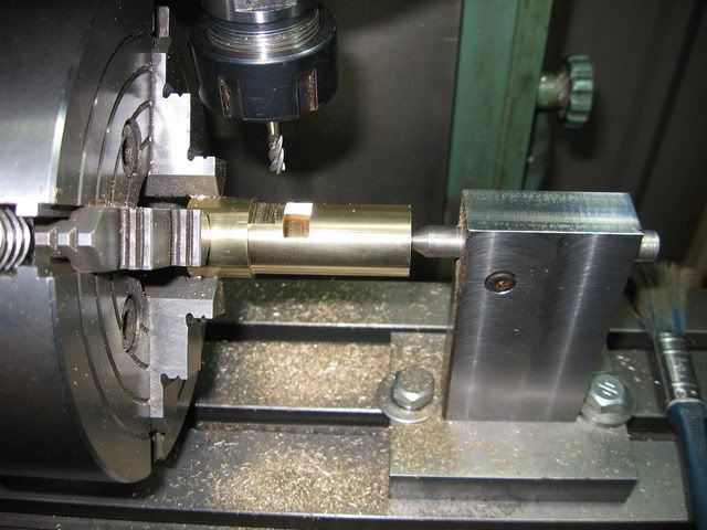
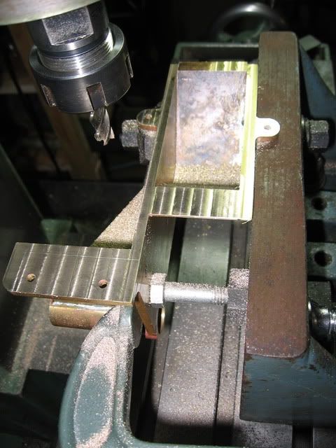
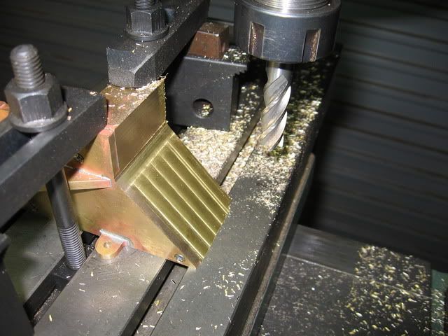
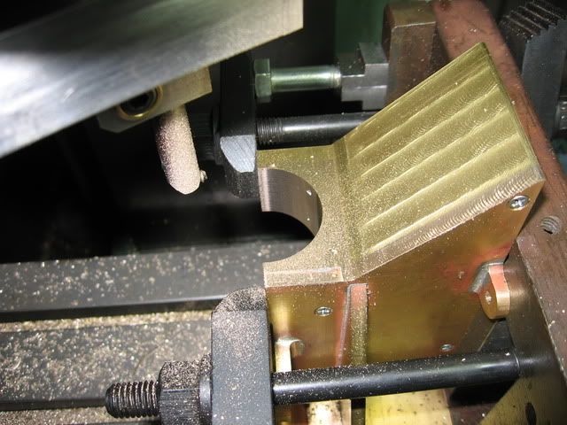
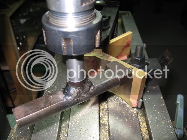
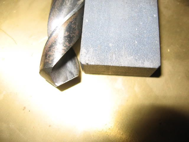
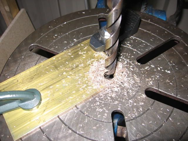
I made the cutter out of an old broken 1/4" endmill. Then put the radius in on the milling machine. The part is sitting on top of a couple of parallels.

IMG_0733.jpg


IMG_0734.jpg


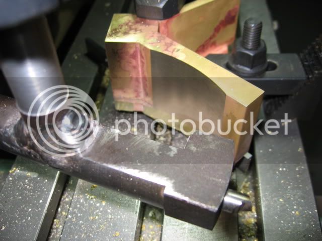
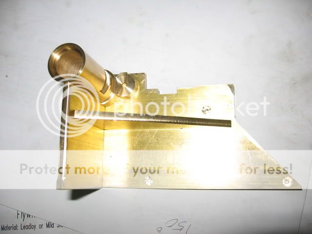
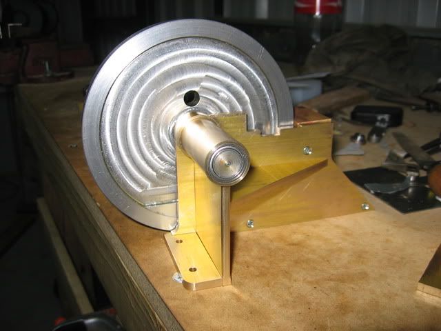
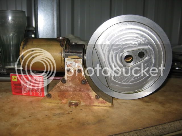
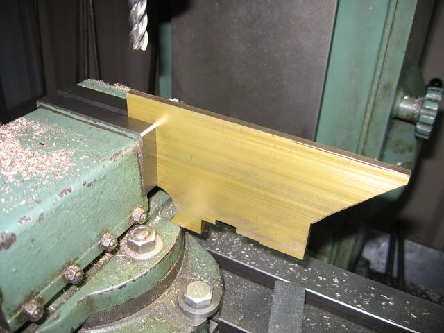
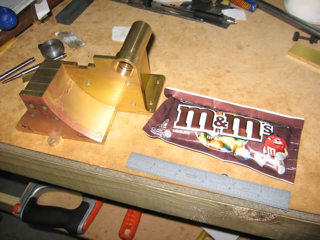
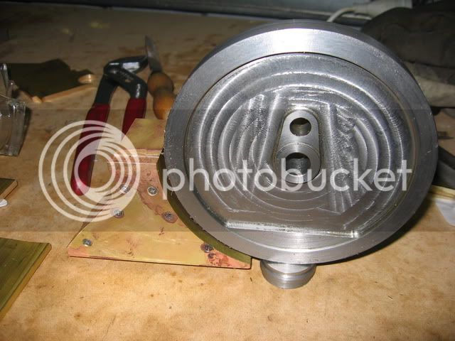
Here's a pic showing how the flywheel sits against this part. At the end the screws will be covered with filler and paint.

IMG_0735.jpg


That's it for now
 
Hi Steve,

Like your cutter! Simple but it does the job. Seems that you have quite a thin wall left on the leg after cutting the radius? Anyway looks good!

Regards Jeroen
 
Thanks Jeroen

I was thinking along these lines as I was cutting it, sure looked like it was going to end up awfully thin. But it didn't quite end up that way. The piece started out 12.7mm (1/2") thick and is now about 5mm in the thinest spot. So it's plenty thick enough as it doesn't have to do very much structurally.

Steve
 
5mm for sure is enough, even if it would have a constructural function!
You told about to use filler for the screws. Probably its my inadequate painting skills, but after some time I always start to see the screws (that I filled) trough the paint. It seems that the filler becomes thinner after a month or 3. When working with brass I try to use brass screws and instead of using filler I fill them with soft solder. After clean it up with a file, sandpaper and spraying you cannot see any mark of a hole, also not after some months. Maybe just an alternative for the filler.

Regards Jeroen
 
This is still coming along nicely Steve. The silver soldering looks good and that little radius flycutter did a great job too. Looking forward to more !!

Bill
 
Thanks Jeroen and Bill

Jeroen, the solder instead of filler sounds like good advice to me. I think I'll follow it.

Cheers
Steve
 
I'm currently struggling with keeping the description of this build coherent. I got some fire bricks to help silver solder the frame together a couple of weeks back, but stupidly left them at my parents house which is 8hrs drive away. :wall: :toilet: Anyway I need to head down that way next week on other business.

The next item is the spine for the frame. I'm making this from a piece of 3/16 thick rectangular section brass.

I started with a 1" diameter hole that had to be bored in the top right hand corner. I started by drilling a half inch hole in the drilling machine. I'll give a little description of this in case anyone doesn't know about drilling holes in brass. This is the sort of opp where it's easy to make a stuff up and even suffer an injury. Hopefully the many people who already know this "inside out" will forgive me for boring them. The first thing one needs to know is that a key reason for an ordinary drill having a twist in it is to provide positive rake. This positive rake makes the drill tend to grab when drilling brass, copper etc. When drilling larger holes this becomes worse :fan:

The trick is to put zero rake on the lip of the drill using a stone. In this pic you can see that I have touched up the lips of the drill to have zero rake (see the shiny line at the cutting edge). Also shown is the stone I used to do this. Because the stoned surface is so small it is pretty easy to sharpen the zero rake off if need be.

IMG_0717.jpg


Then I drilled the hole. Clamped for safety (drilling machines are potentially dangerous!!)

IMG_0719.jpg


Next bored the hole to size in the mill

IMG_0720.jpg

 
From here milling the outside to shape

IMG_0721.jpg


IMG_0722.jpg


IMG_0724.jpg


I'll try to post some more tomorrow or so

Cheers
Steve

 
Hi Steve,

Nice work on the brass and thanks for the tip of the rake angle! I indeed noticed that a standard drill can be very "bitty". Next time I will give it a try.

Curious about the end shape of the part you are making, I cannot visualize the end result yet. :)

CU regards Jeroen
 
Thanks Jeroen

I'll post a mock up of how it goes together very soon. Hope you're enjoying your trip.

Steve
 
The next piece is the crankshaft housing. There is a pinion cut in the middle of the crankshaft and the housing has a slot to allow access.

IMG_0728.jpg


I'm using ball races for the crank

IMG_0736.jpg
 
So here are some mock ups of how it goes together

IMG_0747.jpg


IMG_0742.jpg


IMG_0740.jpg


That's not the real crankshaft in the last photo. There's actually a pulley that goes on the opposite end to the flywheel.
 
You're really doing a nice job, Jeroen. Gotta say, looking at all this brass kind has me breathing heavy...

Chuck
 
Its really coming together nicely Steve...and as Chuck said...that is some SERIOUS brass you have there!!

Bill
 
Thanks Chuck and Bill

Yes lots of brass. I gave the poor fella at the metal supplies a hell of a job cutting it all up. But he's very helpful.

I bought some silver solder the other day. It's a product I don't know anything about, called silver solder but looks like soft solder. Does anyone know about this stuff? I'm thinking of soldering the crankshaft housing on with it. Is it stronger than plumbers solder?

Steve
 
Thanks Pat. Those M&Ms lasted about 2 seconds after I opened them. Been a bit tied up with work lately, but things are looking good to get some more done this weekend

Cheers
Steve
 
I found out on the Internet somewhere that silver in soft solder improves strength. I finally managed to solder the base together using the soft silver solder.

IMG_0759.jpg


Then I milled the bottom roughly flat, clamped onto an angle plate and using a 3/8th endmill with light cuts

IMG_0761.jpg


Note the bolt used as a spacer, I face the top of the bolt flat in the lathe.
 
Then I cleaned the back of the assembly up

IMG_0762.jpg


IMG_0763.jpg


Next is to cut out the piece where the cylinder assembly attaches. Anyway, glad that parts over th_wav. I was finding it a little taxing.

Regards Steve
 
I made a little more progress this evening. I set the base up on the angle plate to cut out the radius where the cylinder assembly fits onto the base. Here's the angle plate held in the bench vice to set up the job. I used a square to line it up

IMG_0764.jpg


Then in the milling machine, using the boring head as a fly cutter

IMG_0765.jpg


and finally, here's a mock up of how things go together

IMG_0766-1.jpg


Steve
 
Making great progress Steve, In that last pic ist beginning to look like a real engine!! Nice job on that flywheel too if I hadn't said that earlier in the thread. Will you leave the various metals natural or are you planning to paint it?

Regards,
Bill
 
Back
Top