
You are using an out of date browser. It may not display this or other websites correctly.
You should upgrade or use an alternative browser.
You should upgrade or use an alternative browser.
Plunket Jr. Build
- Thread starter swilliams
- Start date


Help Support Home Model Engine Machinist Forum:
This site may earn a commission from merchant affiliate
links, including eBay, Amazon, and others.
You are doing some very, very nice work there. There seem to be a number of us all building i.c. engines at the same time right now, and they are mostly all different. Great work!!!---Keep it up.----Brian
Thanks Chuck - Yes the ER chuck is a 2nd MT, I use a bolt and washer in the back as a draw bar. I also use it as a drill chuck in the lathe when I need to hold the drill particularly accurately. It's proved very useful and didn't cost very much, especially since I already had the collets for the mill.
http://www.ctctools.biz/servlet/the-53/ER25-MT2-COLLET-CHUCK/Detail
Brian - thanks for the nice comments and checking in. I think your work is very very nice too, I must check in on your thread. I will be following the finish of your build.
http://www.ctctools.biz/servlet/the-53/ER25-MT2-COLLET-CHUCK/Detail
Brian - thanks for the nice comments and checking in. I think your work is very very nice too, I must check in on your thread. I will be following the finish of your build.
So I made the piston rings following Bill's description in his thread,
http://www.homemodelenginemachinist.com/index.php?topic=6014.235
which I found very useful
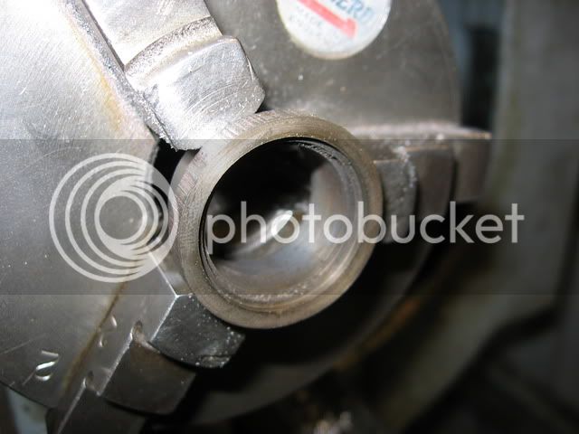
I made a bit of a false start as I proceeded to turn the OD and forgot to leave the extra on to be turned off later. I'm chalking that one down to too many after work drinks on Friday *beer* (my story and I'm sticking to it). Here's a shot of boring out the initial aborted attempt. BTW I think I've mastered using macro mode in my camera, amazing what you can find in the instructions!
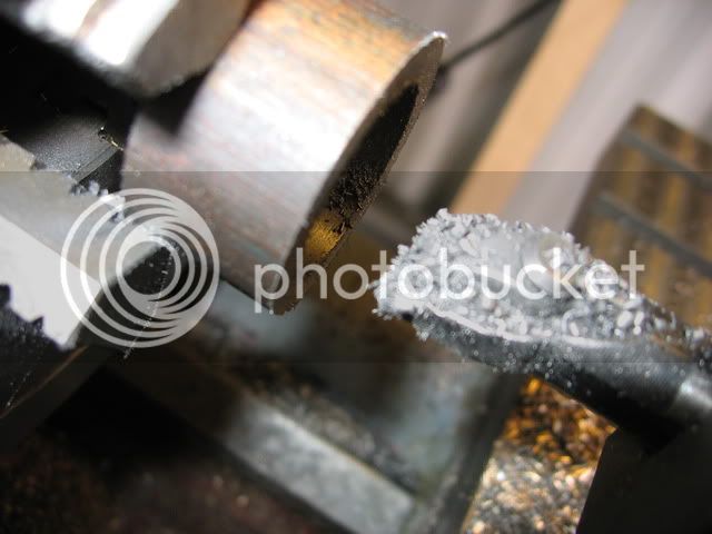
So I stuffed the OD of that up and had to start again :toilet:
http://www.homemodelenginemachinist.com/index.php?topic=6014.235
which I found very useful
I made a bit of a false start as I proceeded to turn the OD and forgot to leave the extra on to be turned off later. I'm chalking that one down to too many after work drinks on Friday *beer* (my story and I'm sticking to it). Here's a shot of boring out the initial aborted attempt. BTW I think I've mastered using macro mode in my camera, amazing what you can find in the instructions!
So I stuffed the OD of that up and had to start again :toilet:
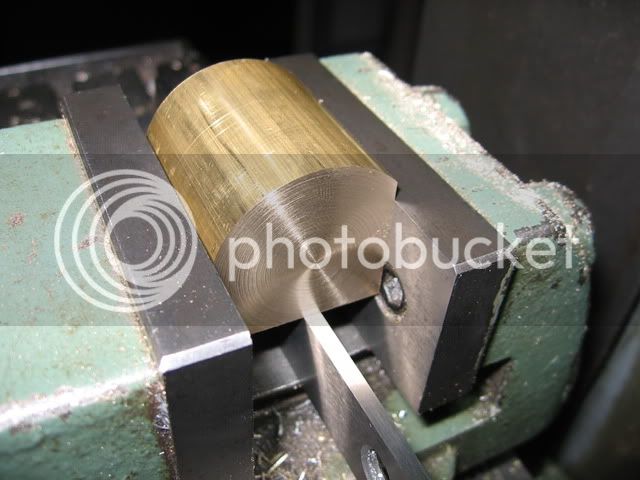
I took Bill's advise and made enough for a few extra in case I break some. Good advise it turned out to be too, as I ended up needing to experiment and broke a few. Here's a pic of the initial turning, I just used ordinary grey cast iron
The final OD is 1". I made the initial OD 30 thou oversize and will slit them with a 1/16" slitting saw. In hindsight I should have made them 40 thou oversize. The initial ID is about 0.89" and the final was 0.92"
Here's a pic of parting off the rings using the same tool I ground up to groove the piston
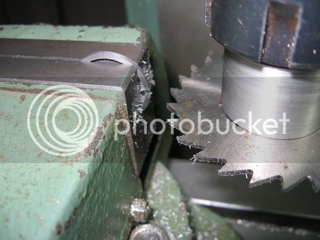
Next I slit the rings
then made a simple fixture to clamp them in the lathe again and turned the OD with the rings closed up. I used a pair of multigrips to close the rings while tightening up the fixture. The ring is between the washer and the aluminum fixture held in the chuck. This is after its been turned to final size making it a little hard to identify.
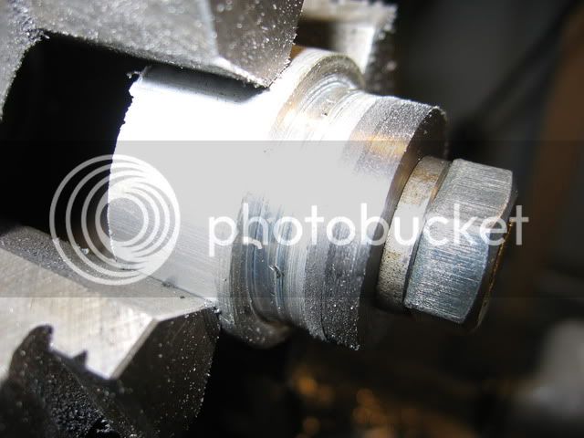
then made a simple fixture to clamp them in the lathe again and turned the OD with the rings closed up. I used a pair of multigrips to close the rings while tightening up the fixture. The ring is between the washer and the aluminum fixture held in the chuck. This is after its been turned to final size making it a little hard to identify.


$24.99
$34.99
Bowl Sander Tool Kit w/Dual Bearing Head & Hardwood Handle | 42PC Wood Sander Set | 2" Hook & Loop Sanding Disc Sandpaper Assortment | 1/4" Mandrel Bowl Sander for Woodturning | Wood Lathe Tools
Peachtree Woodworking Supply Inc


![DreamPlan Home Design and Landscaping Software Free for Windows [PC Download]](https://m.media-amazon.com/images/I/51kvZH2dVLL._SL500_.jpg)
$0.00
DreamPlan Home Design and Landscaping Software Free for Windows [PC Download]
Amazon.com Services LLC

$519.19
$699.00
FoxAlien Masuter Pro CNC Router Machine, Upgraded 3-Axis Engraving All-Metal Milling Machine for Wood Acrylic MDF Nylon Carving Cutting
FoxAlien Official


$89.99
Outdoor Wood Boiler Water Treatment Rust Inhibitor- AmTech 300 & Test Kit
Alternative Heating & Supplies


$99.99
AHS Outdoor Wood Boiler Yearly Maintenance Kit with Water Treatment - ProTech 300 & Test Kit
Alternative Heating & Supplies


$94.99
$109.99
AHS Woodmaster 4400 Maintenance Kit for Outdoor Wood Boiler Treatment
Alternative Heating & Supplies


$29.95
Competition Engine Building: Advanced Engine Design and Assembly Techniques (Pro Series)
Amazon.com Services LLC


$39.99
$49.99
Sunnytech Low Temperature Stirling Engine Motor Steam Heat Education Model Toy Kit For mechanical skills (LT001)
stirlingtechonline


$40.02
$49.99
Becker CAD 12 3D - professional CAD software for 2D + 3D design and modelling - for 3 PCs - 100% compatible with AutoCAD
momox Shop


$12.56
$39.95
Complete Plans for Building Horse Barns Big and Small(3rd Edition)
ThriftBooks-Atlanta


$24.99
$27.99
HOZLY 5PCS/Lot ISO30 Tool Holder Clamp Flame Proof Rubber Claw CNC Machines Automatic Tool Changer
HOZLY


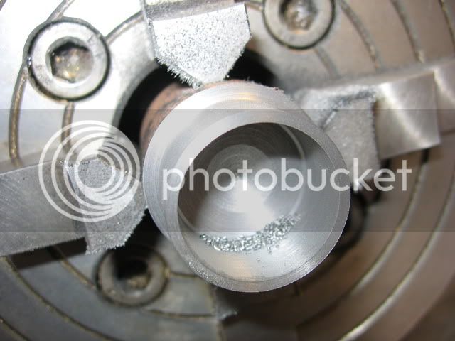
Finally I bored the rings ID's out and did a little facing to bring them to correct width. To do this I bored a recess in the bit of cast iron I stuffed up earlier
I then held the rings in the recess with super glue. After boring I heated it up to break the super glue bond.
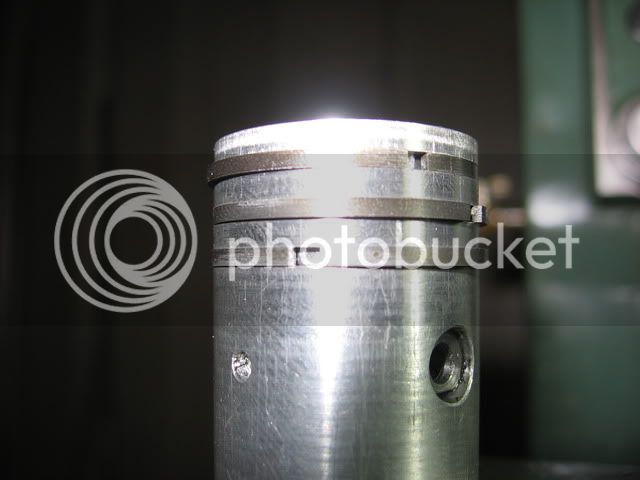
So here they are assembled on the piston
I then held the rings in the recess with super glue. After boring I heated it up to break the super glue bond.
So here they are assembled on the piston
- Joined
- Jul 3, 2010
- Messages
- 278
- Reaction score
- 10
Hi Steve,
Nice job on the piston and rings (and of course the other parts!). How did you get them on the piston without braking them?
When I build my Lister engine I broke the rings in the first 7 attempts, every time just 0.1 second before it would click in its place....very frustrating! Then I made a trapezium support to stretch the rings just a little at a time and more important to keep them straight and non-twisted. With this support I was able to get them over the piston without braking.

Looking forward to read how you managed it, I feel there must be a better way then mine.....(made 10 rings, broke 7, used 2, 1 spare left!)
Have fun, Jeroen
Nice job on the piston and rings (and of course the other parts!). How did you get them on the piston without braking them?
When I build my Lister engine I broke the rings in the first 7 attempts, every time just 0.1 second before it would click in its place....very frustrating! Then I made a trapezium support to stretch the rings just a little at a time and more important to keep them straight and non-twisted. With this support I was able to get them over the piston without braking.
Looking forward to read how you managed it, I feel there must be a better way then mine.....(made 10 rings, broke 7, used 2, 1 spare left!)
Have fun, Jeroen
Hi Jeroen
I like the device you made to do the job. I was able to open them with my fingers and get them over. I don't know why yours always broke when trying that method. Perhaps yours were tighter than mine. Next time I think I'll use a thicker slitting saw, say 3/32 or an 1/8 (3mm) thick for a 1" piston. Then they wouldn't need as much stretching to get over the piston and will be in line with Pat's table.
Cheers
Steve
So I was trying to do my tax return :redface2: but I had a little job to do to finish off the piston. No need to say the tax return has been put aside (again!!)
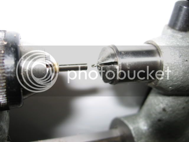
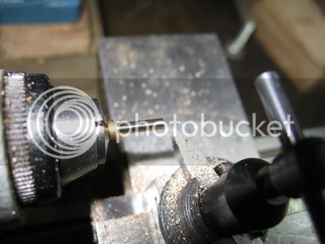
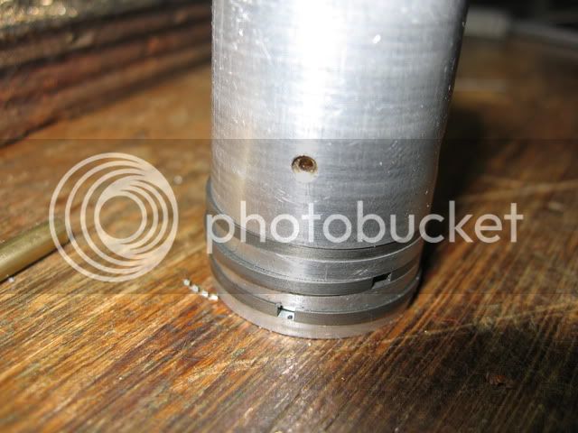
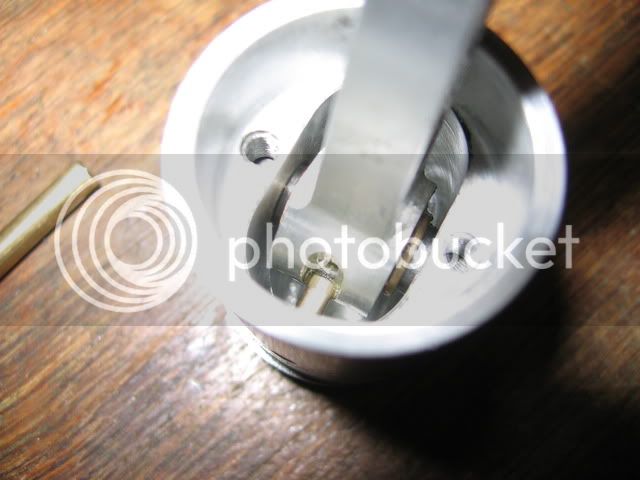
This is the little brass oil pipe to lubricate the conrod's little end. I did it on my 8mm lathe. Here's starting the 1.4mm hole through the middle. I put the drill way back inside the collet so that I could start the hole without a centre drill
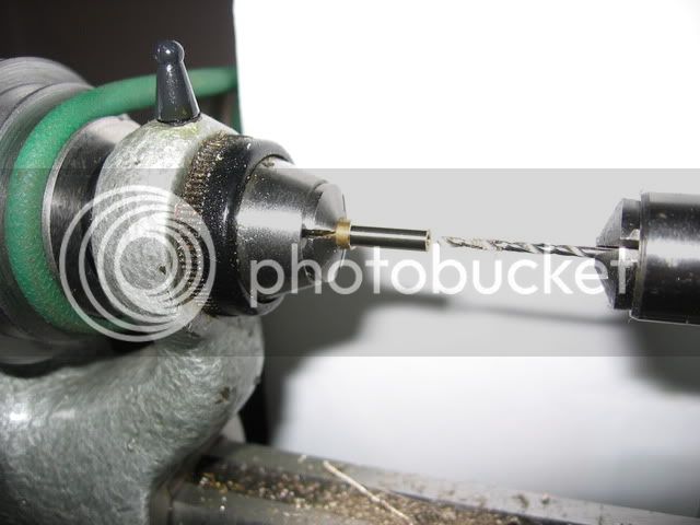
Then drilled the hole out. This lathe is great for drilling small holes
and finished off the OD
This is the little brass oil pipe to lubricate the conrod's little end. I did it on my 8mm lathe. Here's starting the 1.4mm hole through the middle. I put the drill way back inside the collet so that I could start the hole without a centre drill
Then drilled the hole out. This lathe is great for drilling small holes
and finished off the OD
- Joined
- Jul 3, 2010
- Messages
- 278
- Reaction score
- 10
Hi Steve,
Maybe mine were too tight, or I had a different quality of casting Iron. Next time I will try to run an engine without rings, feel that a model engine does not need it to run ok. They normally run some hours in a lifetime.....at least with me they, when it runs the fun is over.....
I have looked at your oil pipe in the piston several times, but I really dont have a clue in what way the oil is supposed to reach the conrods little end..... Maybe I missed something here..... ???
BR Jeroen
Hi Jeroen
Re. no rings. If it turns out no good you can always add them in later, so why not?
The oil pipe is very simple. The piston is orientated horizontally when the engine is finished. There is a drip oiler that feeds through a hole in the cylinder. This drips oil onto the piston, some of which ends up in that oil pipe which then drips onto the conrod, the slot and the hole in the conrod goes through to lubricate the gudgeon pin. Hope that makes sense.
Cheers
Steve
- Joined
- Jul 3, 2010
- Messages
- 278
- Reaction score
- 10
Hi Steve,
Correct, I prepared the groove in the piston so I just can add the ring if required later.
Thanks for the explenation, it makes a lot of sence. I did not realize the piston would be horizontal oh:
oh:
Good luck with the machining, I will be waiting for your new posts to arrive!
Regards Jeroen
Correct, I prepared the groove in the piston so I just can add the ring if required later.
Thanks for the explenation, it makes a lot of sence. I did not realize the piston would be horizontal
oh: Good luck with the machining, I will be waiting for your new posts to arrive!
Regards Jeroen
Thanks Jeroen
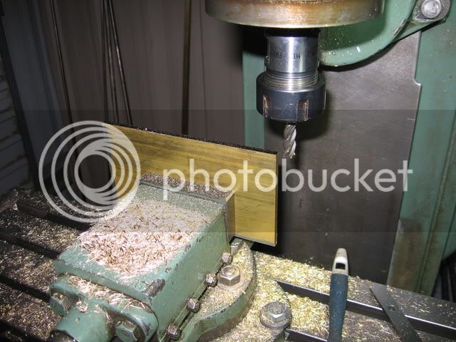
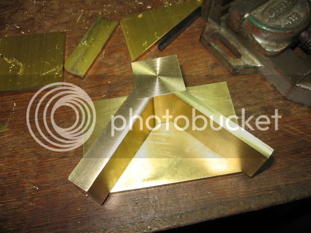
I've started making the base. This is a fairly involved fabrication job and although my enthusiasm for it was pretty flat when I started, over the last couple of days it's steadily picked up. I'm starting to view this as one of the more challenging and interesting parts of the build.
I've mainly been sawing and milling edges so far. Making the odd square from round
This part will be the spine, it was a bit on the large size for my vice, but with light cuts I got there
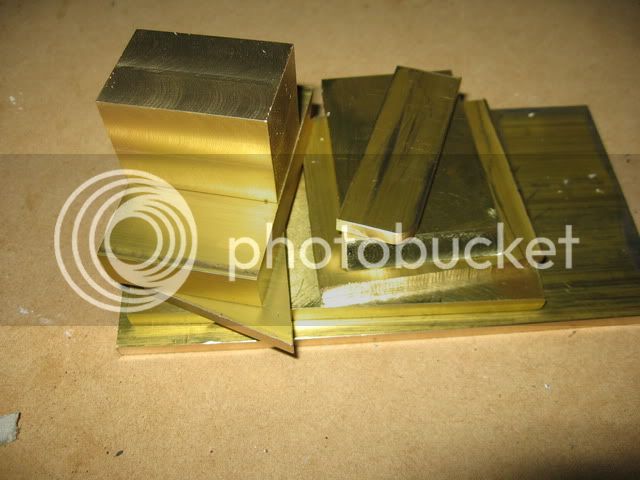
Here's the collection of bits I've cut up for the base so far. There's still a few very small parts I haven't started yet, the only major piece not there is the housing for the flywheel axle. With so many bits you get an idea of how the base is a little involved.
I've started making the base. This is a fairly involved fabrication job and although my enthusiasm for it was pretty flat when I started, over the last couple of days it's steadily picked up. I'm starting to view this as one of the more challenging and interesting parts of the build.
I've mainly been sawing and milling edges so far. Making the odd square from round
This part will be the spine, it was a bit on the large size for my vice, but with light cuts I got there
Here's the collection of bits I've cut up for the base so far. There's still a few very small parts I haven't started yet, the only major piece not there is the housing for the flywheel axle. With so many bits you get an idea of how the base is a little involved.
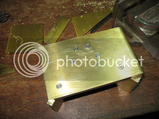
Here's how the side which holds the cylinder assembly is starting out
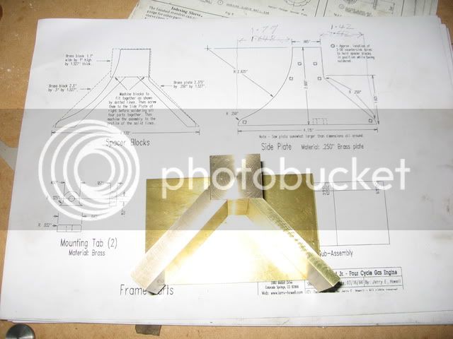
The pieces are first screwed and then silver soldered together. The square piece has a radius cut in the top which forms a cradle to hold the cylinder assembly. The piece on the left has a large radius cut in it to match the flywheel.
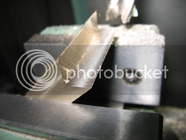
Here's a pic of cutting out the corner in the piece on the left
That's it for now.
The pieces are first screwed and then silver soldered together. The square piece has a radius cut in the top which forms a cradle to hold the cylinder assembly. The piece on the left has a large radius cut in it to match the flywheel.
Here's a pic of cutting out the corner in the piece on the left
That's it for now.
Jeroen, that brass wasn't too expensive as it was mostly just standard rectangular section. All the brass for this project wasn't cheap though, although I bought more than I needed. Thanks for your complements.
So I've done some more work on the base. First I screwed some of the bits together using 2.5mm screws
So I've done some more work on the base. First I screwed some of the bits together using 2.5mm screws
Then I sawed some bits off and attempted to silver soldered it together.
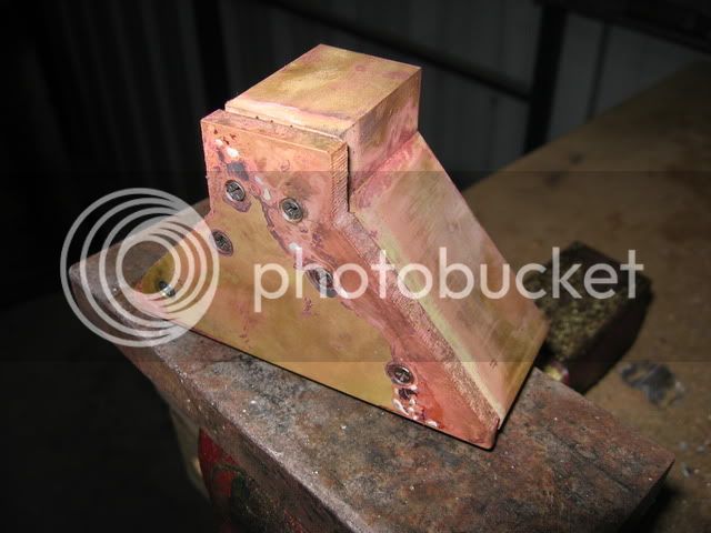
I used some new solder I bought off ebay and I later found out it didn't work properly ???
Anyway that's no biggy, I'll fix it up later.
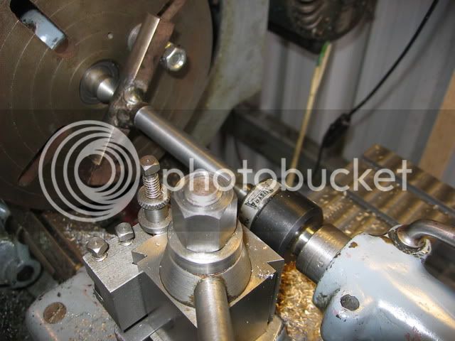
So next I needed a fly cutter for cutting a radius to accommodate the flywheel. I made this from two bits of steel welded together. Here's a pick of turning the shank between centres so I can put it in an ER collet.
I used some new solder I bought off ebay and I later found out it didn't work properly ???
Anyway that's no biggy, I'll fix it up later.
So next I needed a fly cutter for cutting a radius to accommodate the flywheel. I made this from two bits of steel welded together. Here's a pick of turning the shank between centres so I can put it in an ER collet.