Plunket Jr. Build

Home Model Engine Machinist Forum

Help Support Home Model Engine Machinist Forum:

This site may earn a commission from merchant affiliate links, including eBay, Amazon, and others.
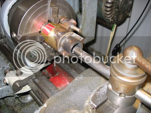
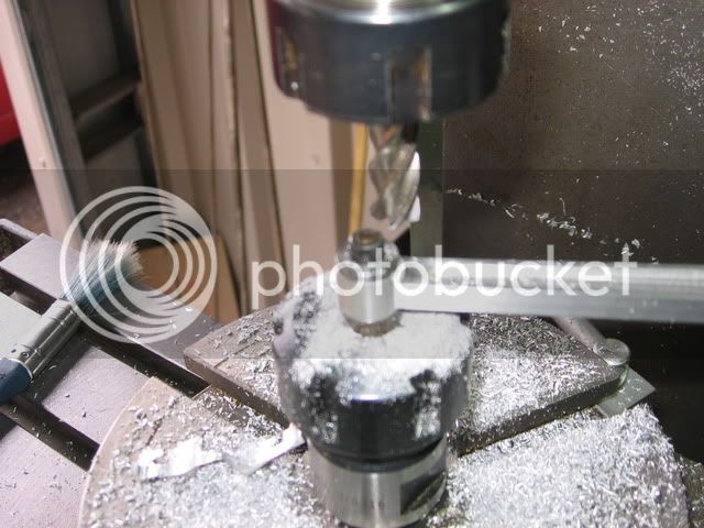
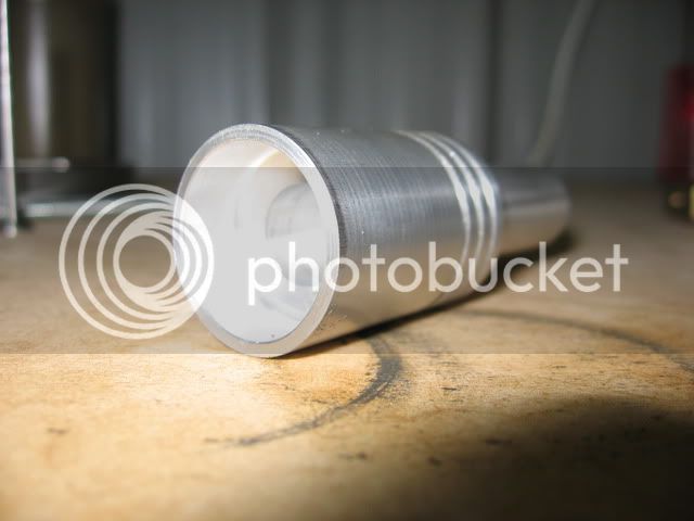
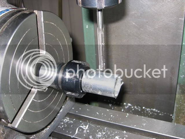
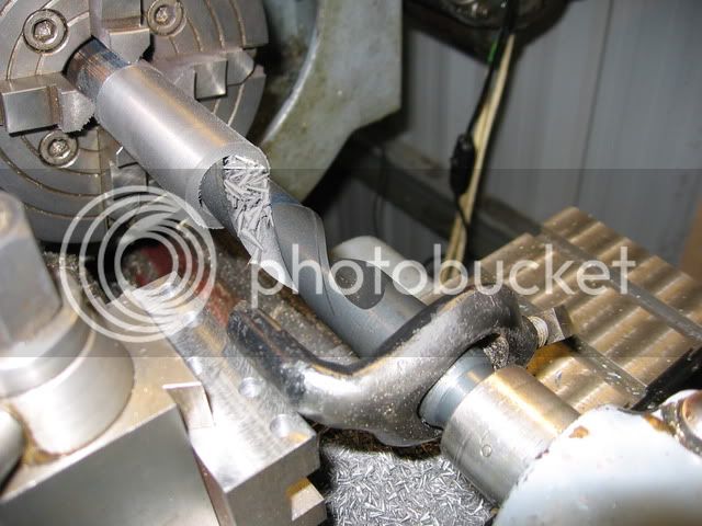
So next I made the liner. This needs a 1" hole bored in it that is 3.2" long. I started by putting some cast iron in the lathe and drilling it with a 7/8" drill. Note the use of the lathe carrier to eliminate the chance of the drill spinning in the Morse taper

IMG_0650.jpg


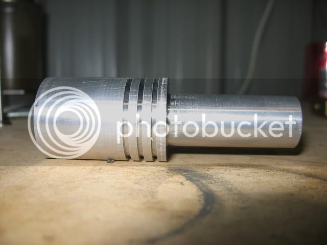
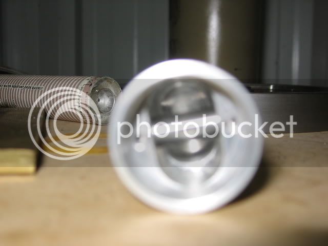
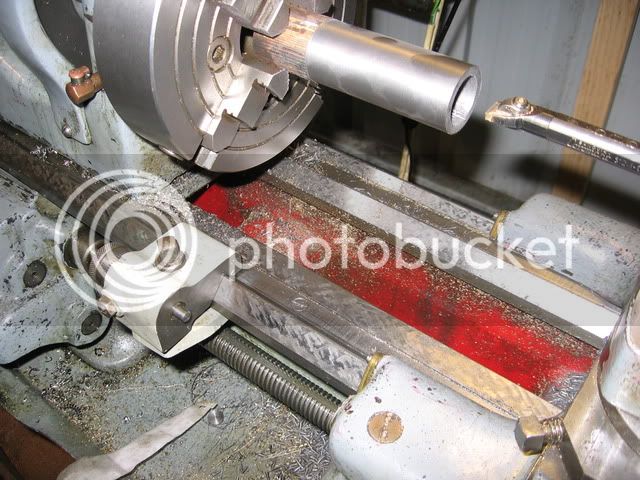
Then I bored the liner out to about 50 thou undersize using a carriage stop to get the depth right

IMG_0652.jpg


IMG_0651.jpg


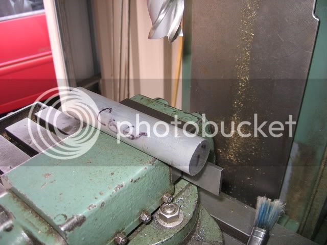
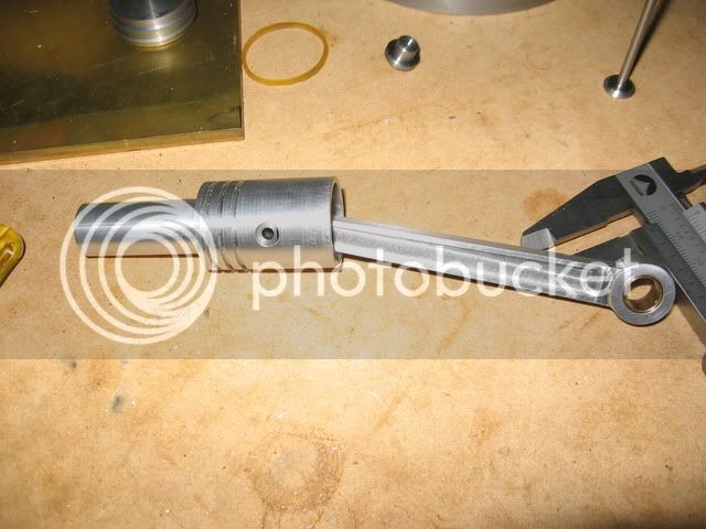
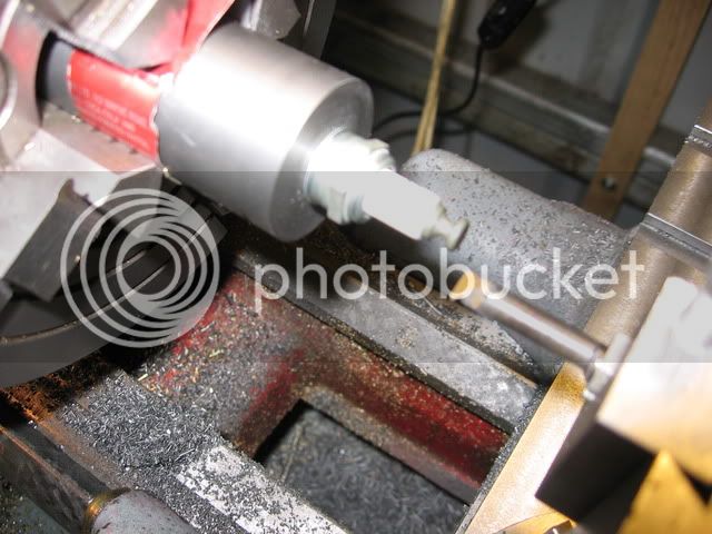
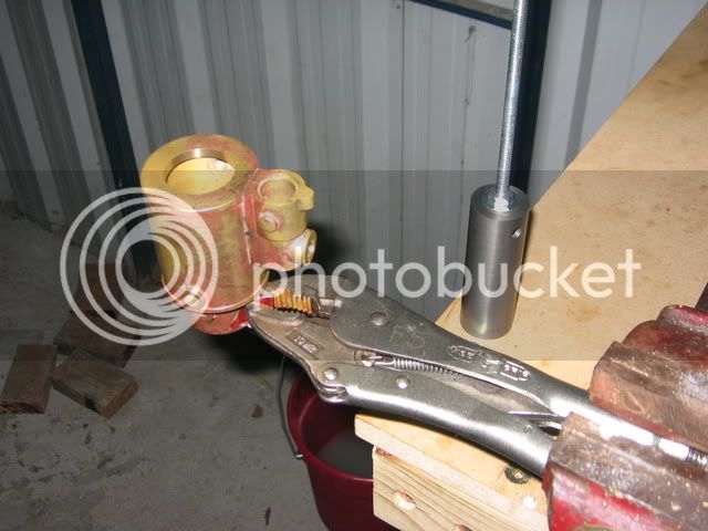
The outside diameter of the liner was made to about 2.5 thou bigger than the housing inside diameter.
 
I needed to put a 10mm by 1mm pitch thread in the other end of the liner for the spark plug. As I didn't have a tap this size and couldn't be bothered tracking one down I just screw cut the thread. I have a 44 tooth change gear and by putting this on the tumbler stud instead of the usual 20 tooth gear, then setting the gearbox to cut 56 tpi, my lathe was set to cut a pitch of 0.998mm which was more than good enough for this job.

The boring bar for the threading is just one I made from silver steel.

IMG_0653.jpg
 
I then heated the housing up with a propane torch and put the liner in the housing

IMG_0655.jpg


IMG_0656.jpg


The inlet exhaust hole is not lined up perfectly between the housing and the liner but I think it's good enough. I'm reasonably happy with how it's turned out.
 
Steve, you have made a lot of progress since i last check in. The silver solder work looks great by the way.

Bill
 
Beautiful fabrication work there. :bow:


Some really nice work here. That lathe dog trick for the drill bit is one I will stuff away for use later on. Thanks for the tip.

Ron
 
Some very nice work there, Steve. Looks like you've done a lot of heavy lifting and it's turning out very nice. I'll be interested in seeing the process of making the engine base. That looks like another fabrication job.

Chuck
 
Bill, NickG, Ron and Chuck, thanks for checking in and for being interested.

Bill, I hope none of the silver solder leaks, I think it's ok (cross fingers)

Chuck, yes the base should be an interesting part of the project. It is held together with screws and then silver soldered. You have just reminded me that I need to order some taps for the small screws I bought for the job.

Cheers
Steve
 
I did some more work on the exhaust valve assembly today.

Here's a fuzzy pic of the main three parts. There is a steel housing that the valve seats against, the bronze valve guide which I made a press fit in the steel housing and the valve

IMG_0658.jpg


There is an 1/8" hole through the valve guide which is not put in until it is in the housing.
 
Here's a pic of the guide assembled in the steel housing. You can see the hole in the side that the exhaust exits through.

IMG_0659.jpg


The next step is to drill the hole through the guide. I drilled a 3mm hole which needs to be 1.5" long which is more than 12 times the drill diameter. I find when drilling very deep holes like this in the lathe that having the drill held dead true makes a big difference with respect to the hole being straight. For this reason I used an ER collet chuck. Next I put a 3.1mm drill and then reamed it 1/8". The hole was still running true when it came out the other side. I know if I used one of my drill chucks that wouldn't have been the case.

IMG_0660.jpg


The valve seat was then turned in with a boring bar. This was done with the same chucking as used for drilling the valve guide.

IMG_0662.jpg


Here's the whole thing put together. I lapped the valve seat a little with valve grinding paste

IMG_0663.jpg


That's all for now 8)
 
The last significant job on the cylinder assembly was to bore out the cylinder to it's final size. I did this with a 5/8" boring bar with a HSS cutter in it. The finish came out good and the bore is parallel. I think I will be able to get away without lapping the cylinder bore.

You can see the exhaust valve guide assembly now installed in the cylinder assembly. I made it a light press fit in the housing.

IMG_0665.jpg
 
Now that the cylinder assembly is largely finished next is the conrod. This is another job involving lots of milling.

This is how it started out, a piece of 1" diameter aluminum meets a 1" diameter endmill

IMG_0668.jpg
 
So the round is converted into rectangle section with a couple of holes that will become the big and little end

IMG_0669.jpg


My basic strategy for making this is to base everything around a pin which will locate the big end. Here's the pin in the embryonic conrod

IMG_0670.jpg


and here it is bolted to the mill table

IMG_0671.jpg


I've set the dials to zero with the spindle in line with the pin. The conrod has two angles. I'll pick these up by swiveling on the pin attached to the table and then make use of a smaller pin in the little end.
 
So now I start milling and can pick up the two angles by running an indicator across the pins

IMG_0675.jpg


So the different pin diameters pick up the two angles by coming at either side with an indicator

IMG_0674.jpg
 
Then after some time things start to look more like a conrod

IMG_0677.jpg


from here I move to the rotary table

IMG_0678.jpg


and eventually

IMG_0679.jpg


Finally I made up some bronze bushes and put in a small slot and hole at the little end for the oil passage.

IMG_0681.jpg


It took quite some time but it's done
 
Lovely job on the conrod Steve, i've always been scared of doing complex shapes like that but you made that look easy. Sure it wasn't easy but will be a good method to follow.

Thanks for showing

Nick
 
Thanks for the nice comments and for checking in Nick, much appreciated.

I've been doing some work on making the piston, here's a couple of shots of it after doing the basic turning

IMG_0683.jpg


IMG_0684.jpg


The grooves were put in with a tool I ground from HSS and the smaller diameter at the end is just to hang onto it while machining. I'll cut it off when I've finished.
 
From here I stuck it on the rotary table and drilled and reamed the hole for the gudgeon pin. There is also a smaller hole for a little oil pipe to lubricate the little end.

IMG_0685.jpg


I then set the rotary table up vertically and milled the clearance for the conrod as well as spotting a couple of holes for some grub screws which will secure the gudgeon pin.

IMG_0686.jpg
 
Here's the inside of the piston

IMG_0688.jpg


and here's the piston assembled with the conrod

IMG_0689.jpg


Next job will be to have a go at making the rings. I'm hoping to have a go at that on the weekend
 

Latest posts

Back
Top