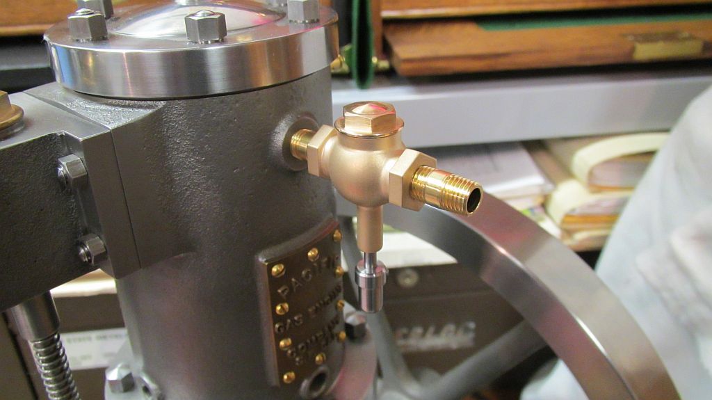
Hi Everyone
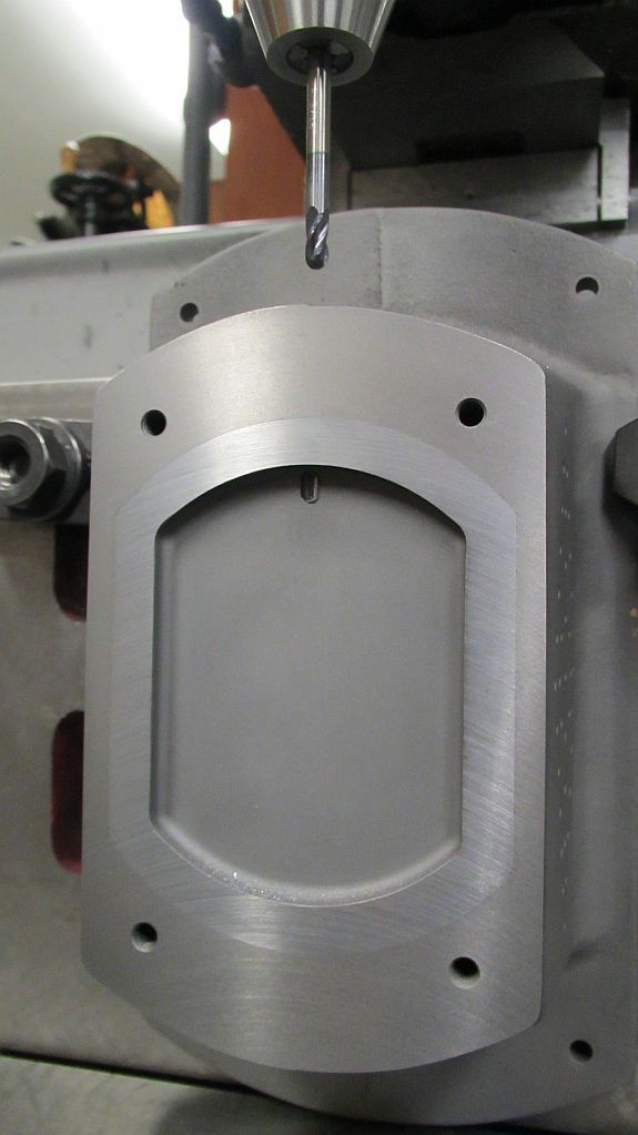
I finally was able to carve out some time to work on the piston trip ignitor. The cylinder casting had bosses cast for the feed throughs; but the way my cylinder finished up I wasn’t completely happy with the position of the boss relative to where the holes should be.
My original plan was to completely remove the boss and counter bore the cylinder to create a flat area for the insulator to sit. I actually did this but then wasn’t overly happy with the way it looked. Part of the reason was I sized the counter bore to fit some mica washers I had on hand; and after the fact the scale just wasn’t correct. So after thinking about it for a few days I decided to go ahead and replace the bosses.
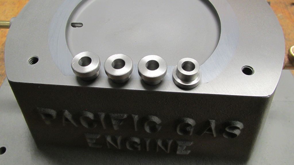
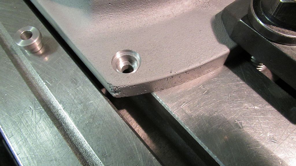
The new bosses were turned and then pressed and Loctited into the counter bore. A small fillet was added with the Devcon and I was starting to feel better about how it was all looking. I have seen these engines both ways (with the counter bore and also with the boss) so I would say either way could be correct.
The Devcon I have been using is called Plastic Steel Putty (A) it is a steel reinforced epoxy; the mix ratio is 9:1 by weight or 2.5:1 by volume. This gives you some idea of the amount of steel filler that it has in it. It is not cheap but a much better product than JB Weld types of epoxies.
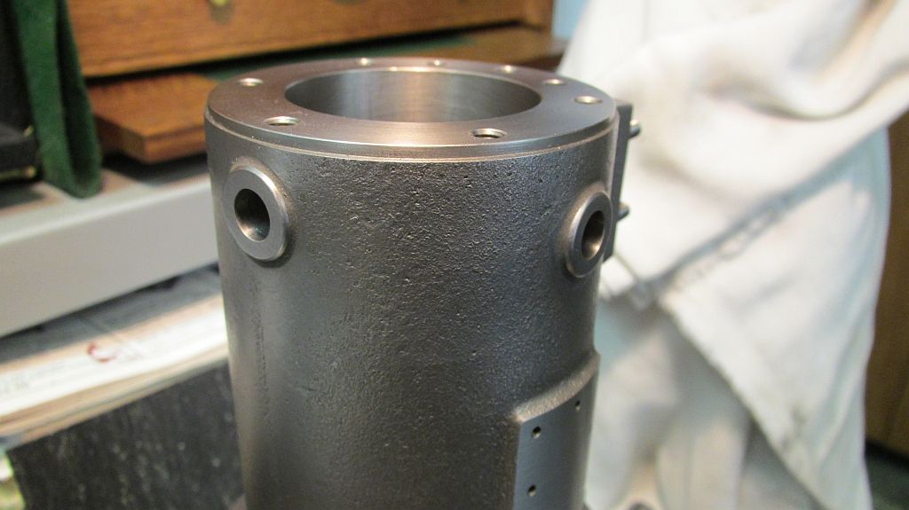
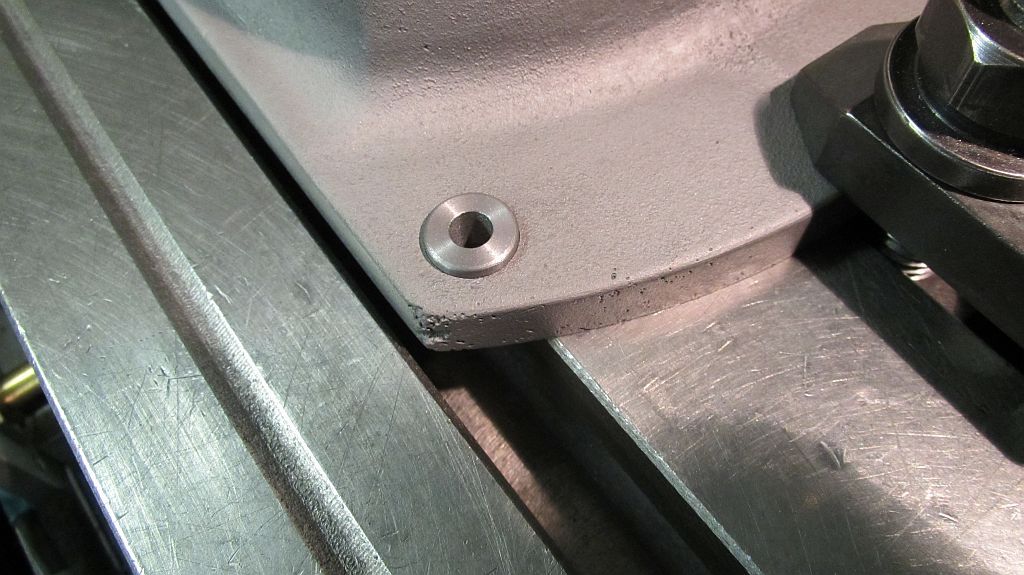
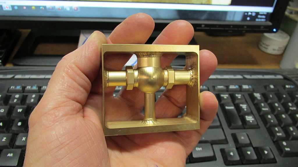
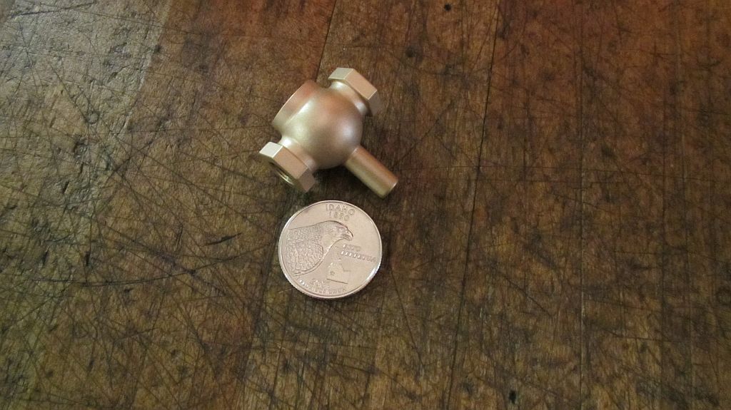
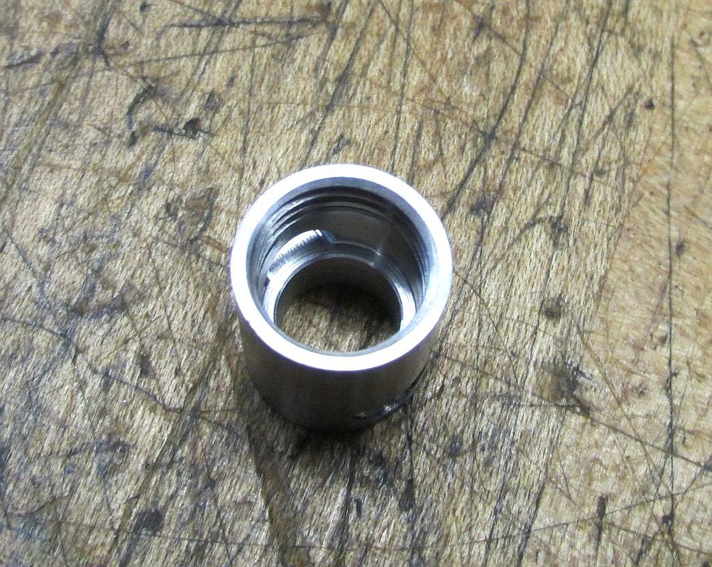
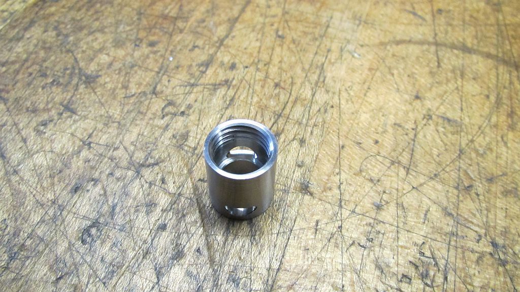
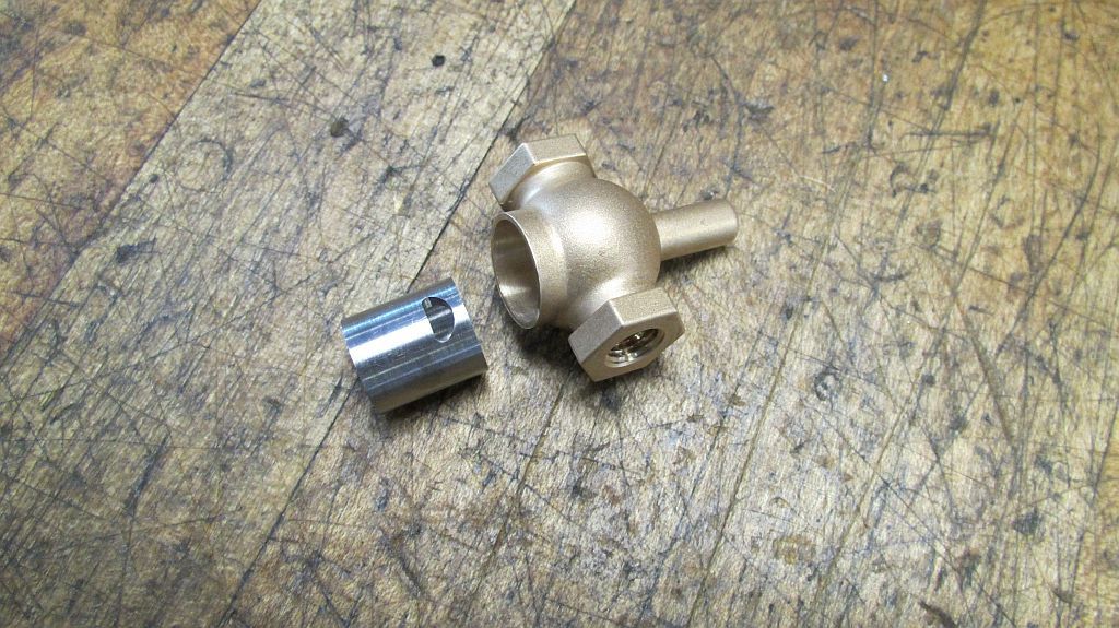
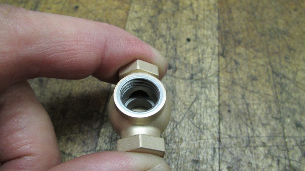
Here are the two new ignitor bosses.

And a close-up shot.
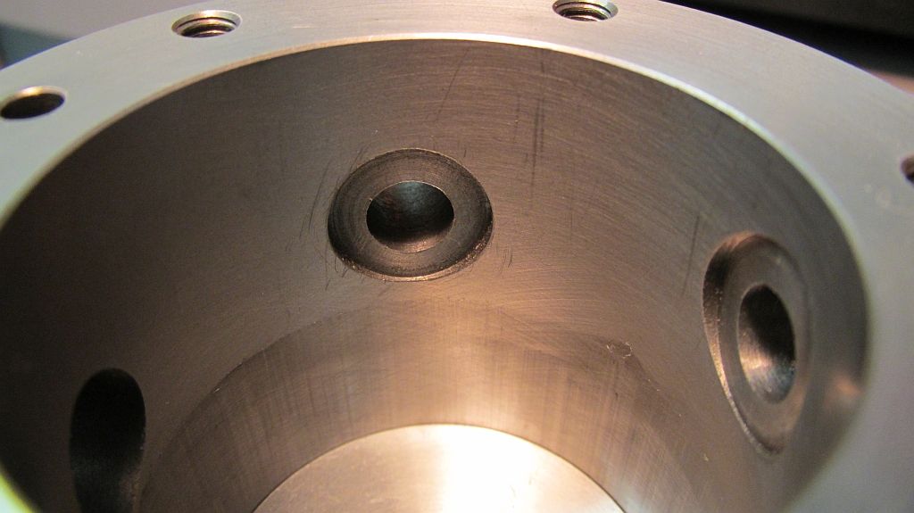
I decided to counter bore the inside of the cylinder for the mica to sit in; as far as I know this is also how the original engine was done. I modified a standard counter bore (cut off) so it would fit in the cylinder bore.
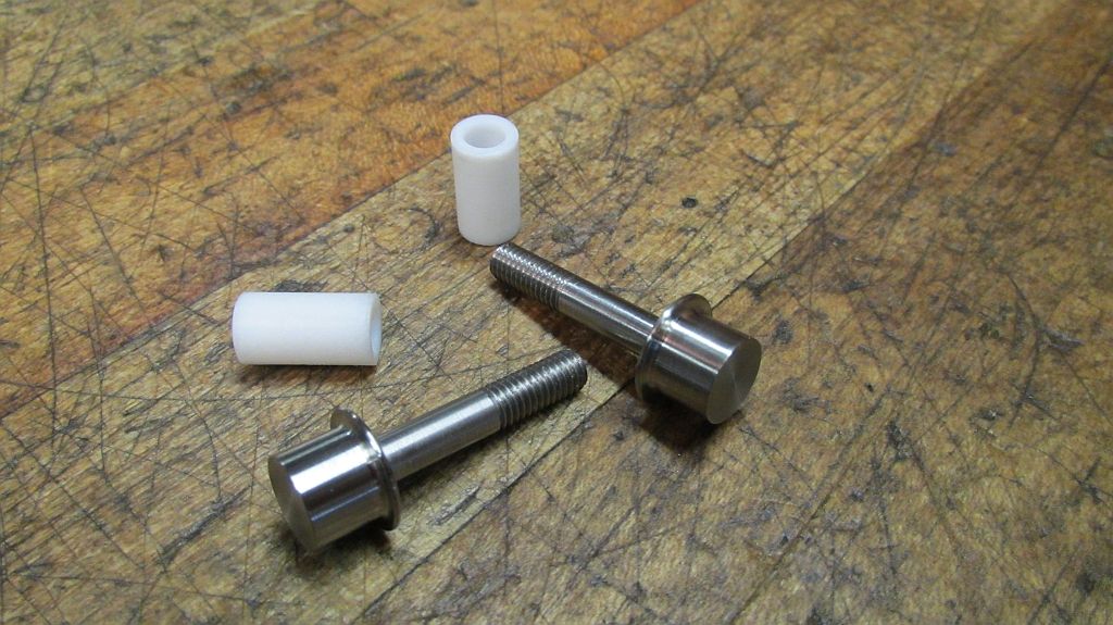
Teflon insulator bushings were turned along with the start of the feed throughs; the feed throughs were made form 303 stainless steel.
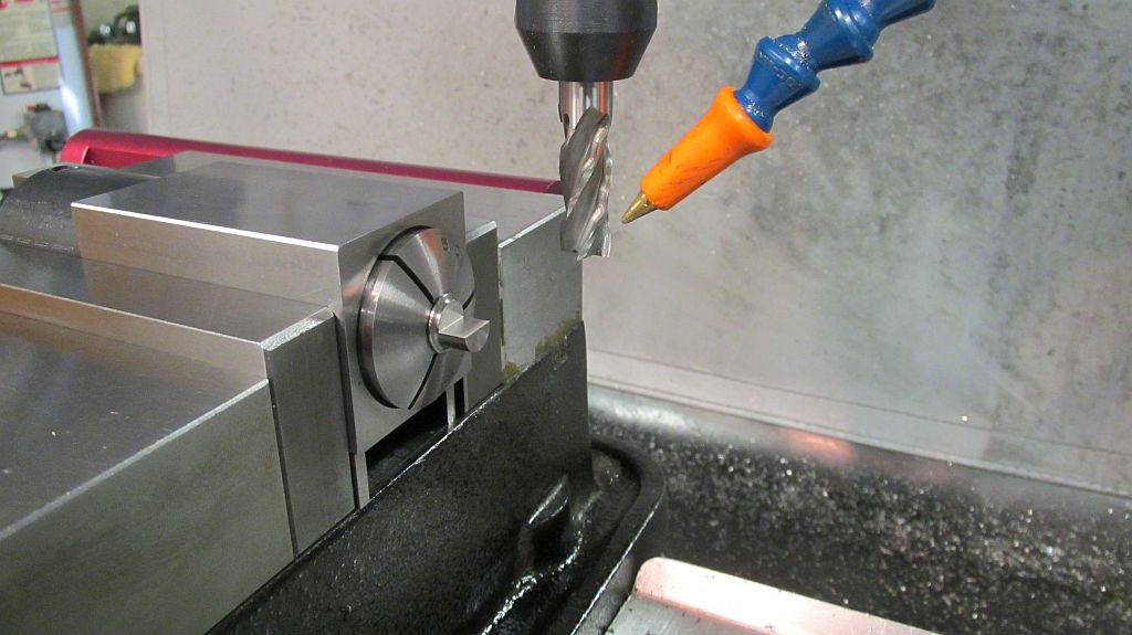
The feed through is milled half way to form the clamp area for the blade.
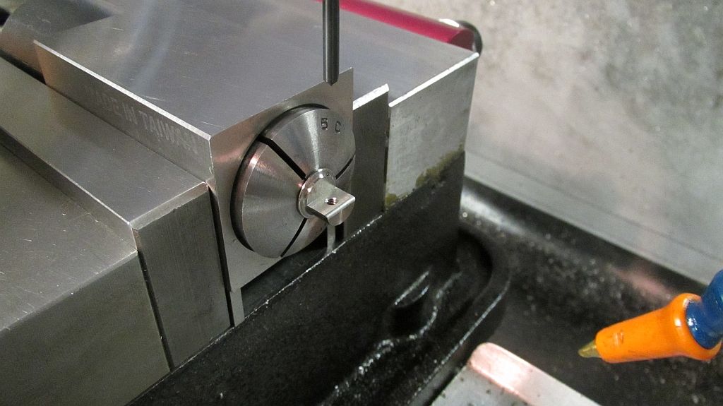
Then drilled and tapped; also the edge is given a small radius to remove a stress point from the balde.
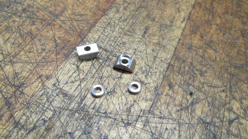
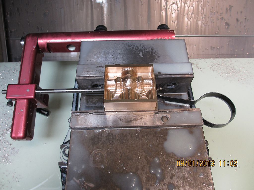
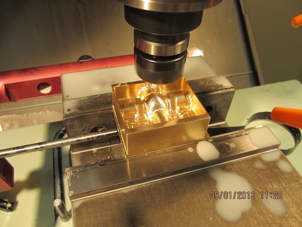
The clamp blocks are machined and counter bored to accept a boss for the clamp screw.
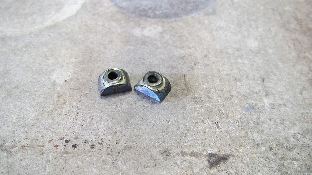
The bosses are silver soldered in place.
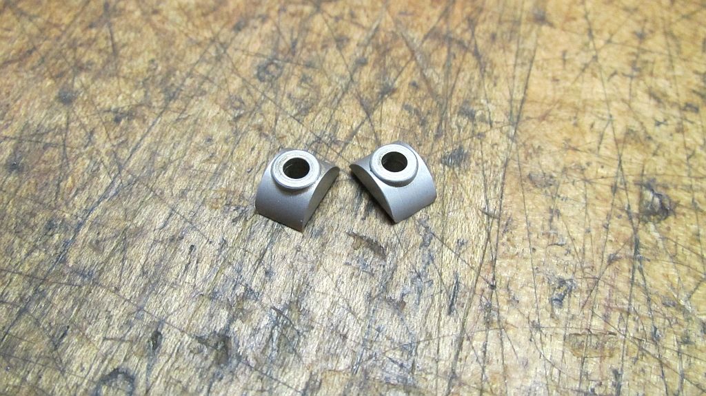
Here they are after cleaning and a trip through the blast cabinet.
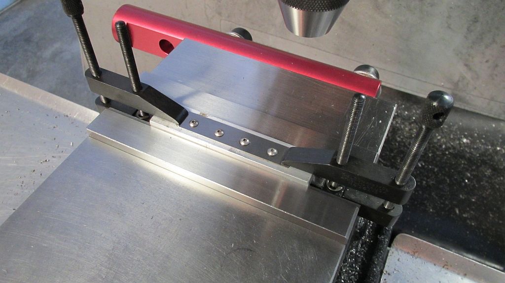
The blades are machined out of a commercial air compressor valve spring; the spring just happened to be the right thickness. The stock is screwed to a chucking piece and the clamps removed.
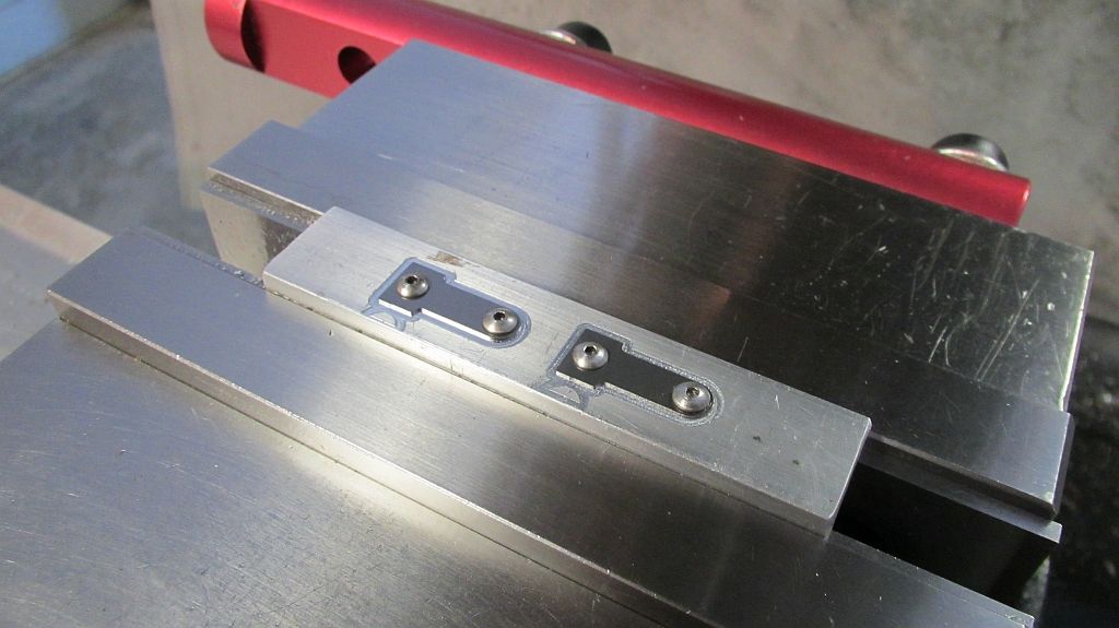
The blades are profiled using a small carbide end mill.
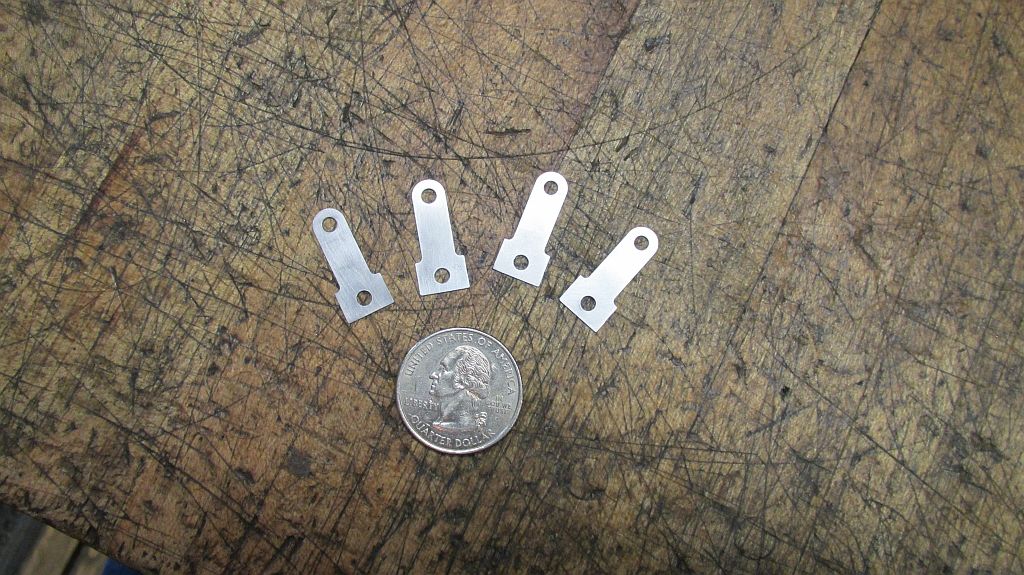
Here they are ready for the points to be installed; also made a couple of spares while I was set up and going.
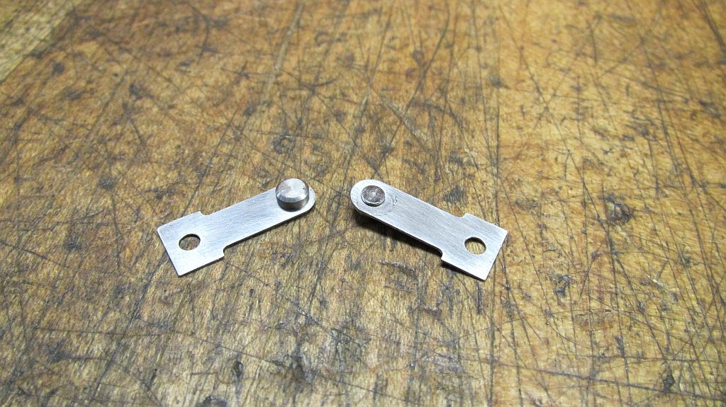
The points were machined out of meteor metal that I purchased from one of the magneto guys a number of years ago. I think that it is high in Nickel but not sure what else is in it. I plan to take a sample to work and have one of the guys in the lab check it out.
I may also try German silver point material as this is what one of the gas engine suppliers is selling for Ignitor point replacements in the full sized antique engines
The points were swaged in place after machining.
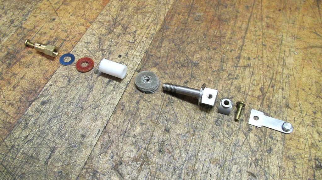
Here is the lineup of all the parts for one feed through assembly. The mica washers are added or removed to properly align the points. The outside insulator is made from linen phenolic followed by a thin washer punched from some blue spring steel and then the brass nut/ wire clamp.
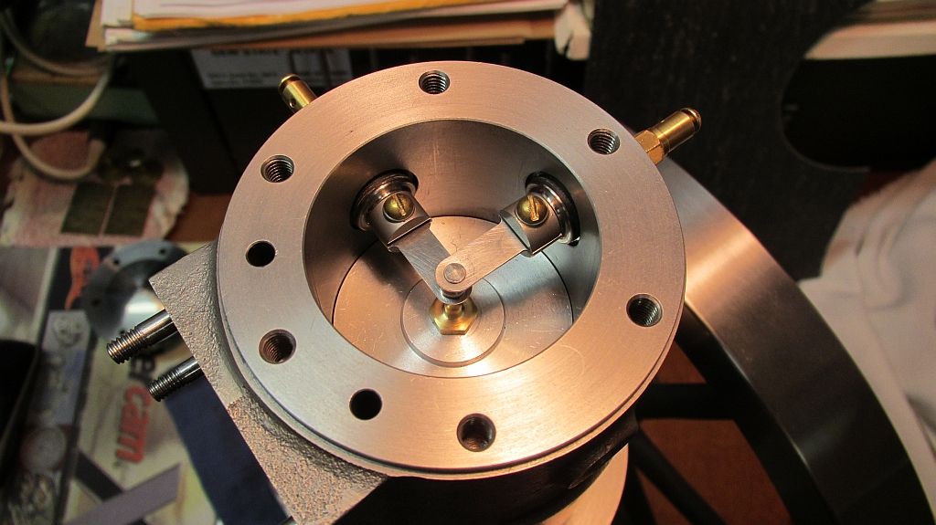
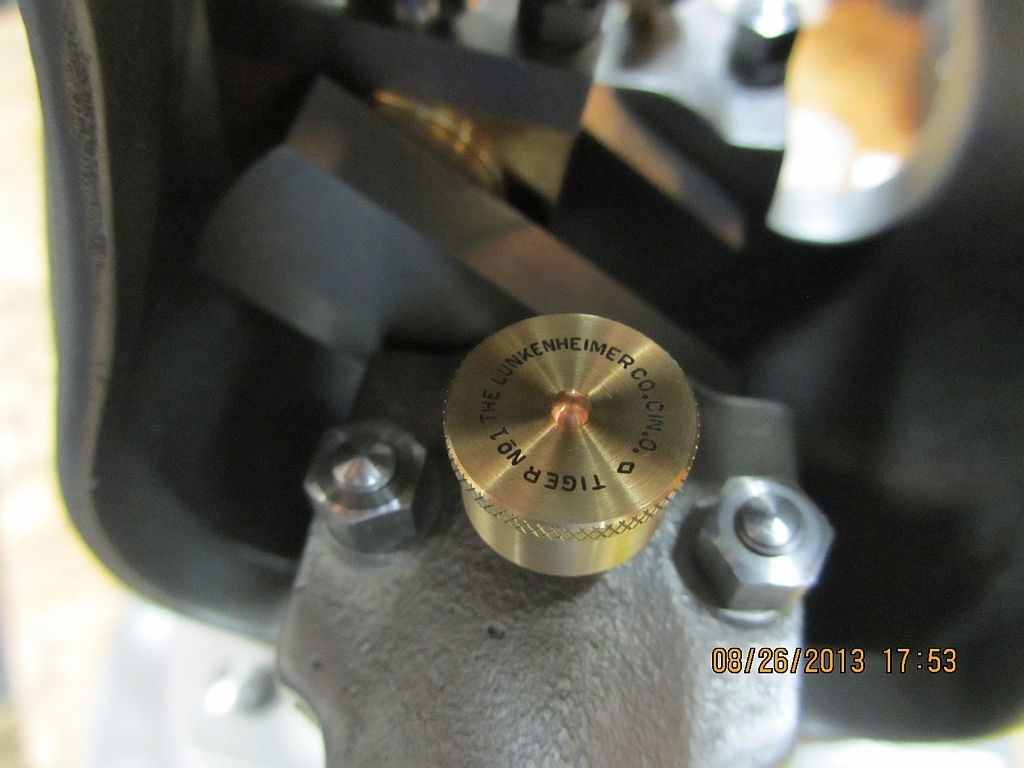
Here are all the parts installed in the cylinder; notice the brass button screwed into the top of the piston.
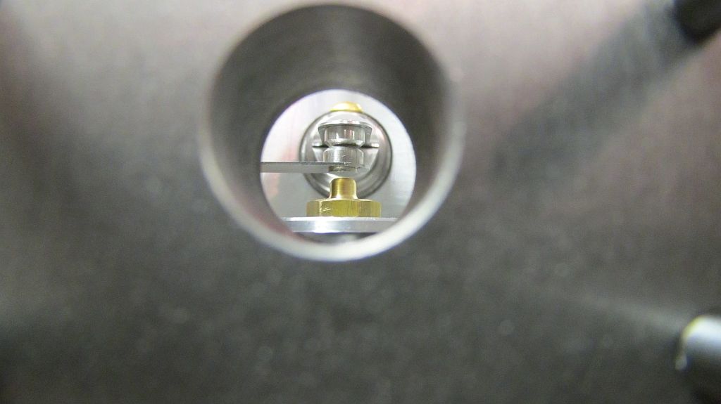
Here is a shot through the exhaust port; the button on the piston closes the points on the way up and then the point open as the piston starts back down.
Because room is tight all fine adjustments will be made using shims; either under the trip button or under the blades. I lengthened my connecting rod to increase the compression ratio so there is not enough room for the stud and jam nut that would have originally been used on the top of the piston.
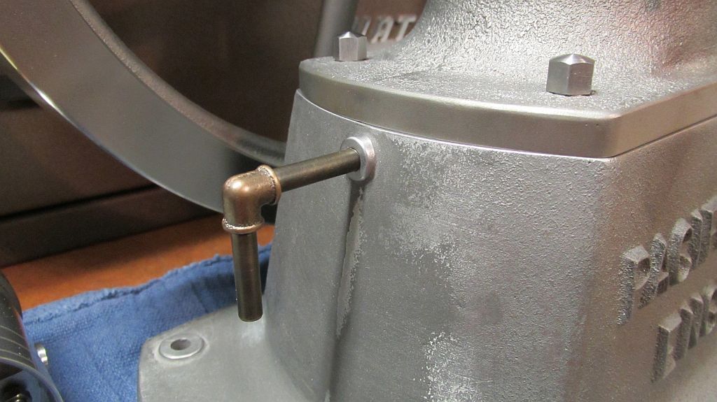
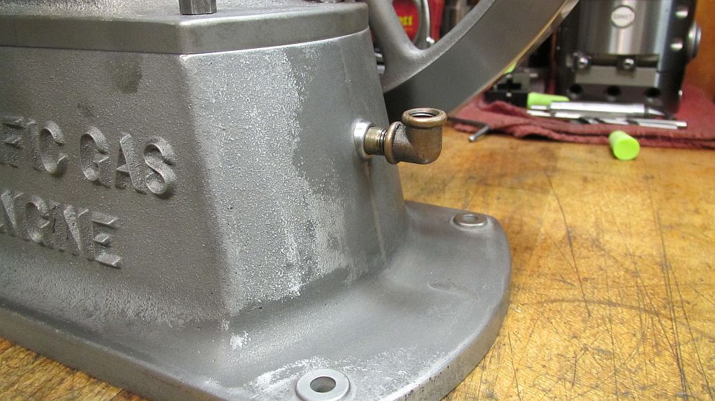
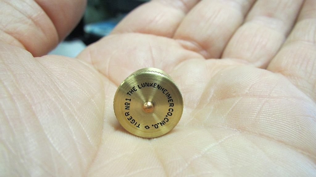
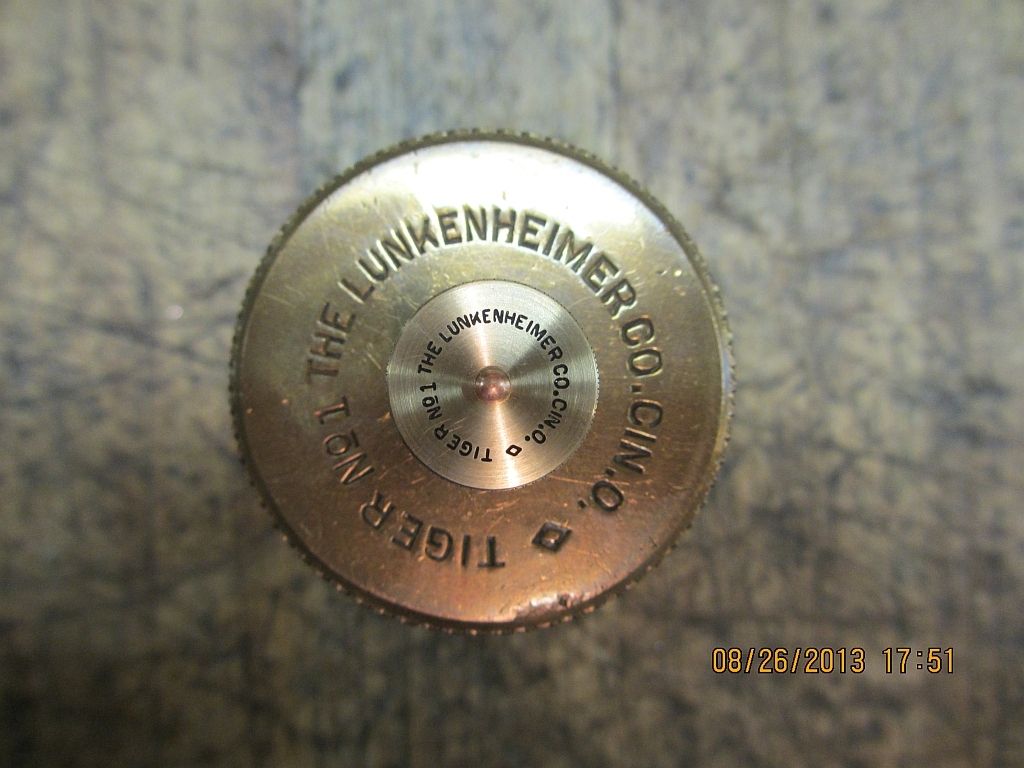
Here are a couple shots of the outside parts.
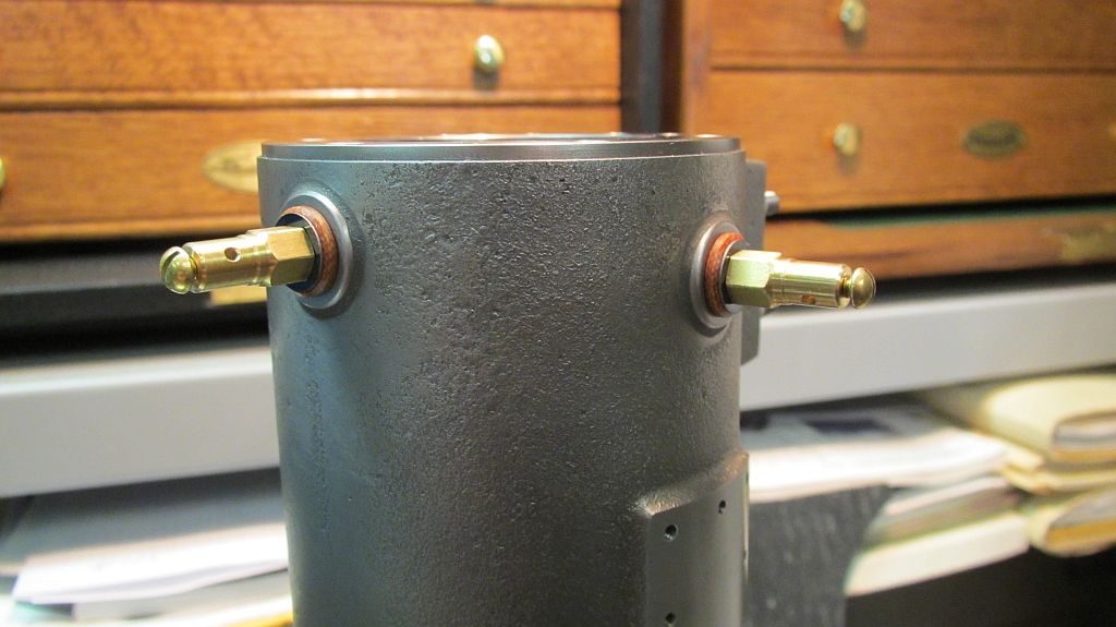
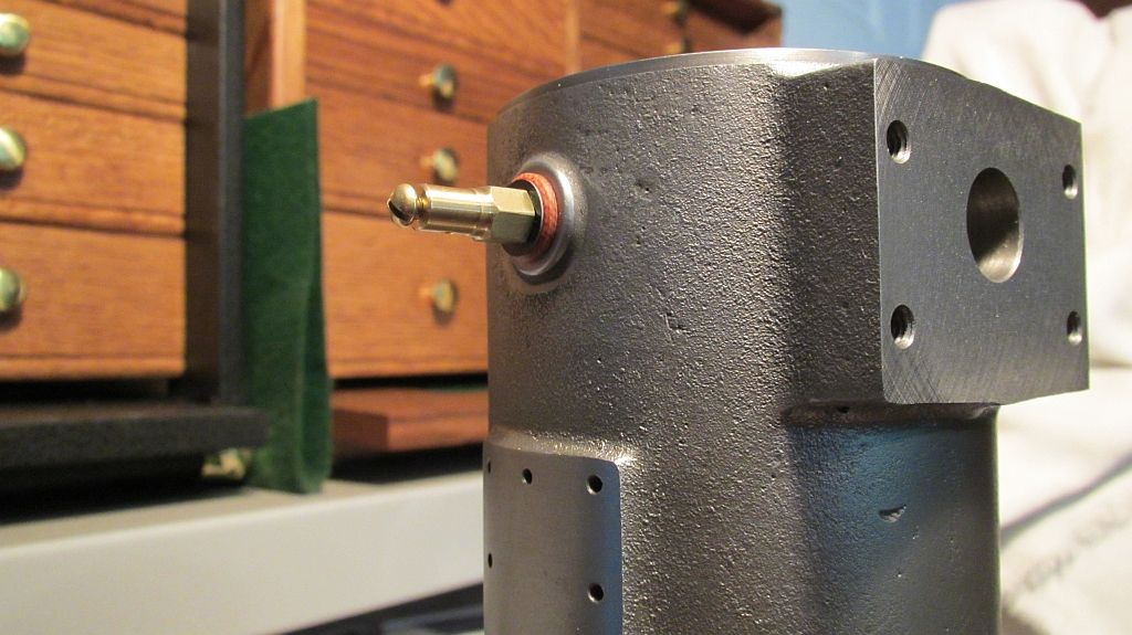
The major problem with this system is there is no spark advance; the engine will always runs in a retarded condition. It was 1890 after all and this engine represents some of the very early US engine development.
Thanks for checking in.
Dave


