Oscillating I.C. Engine

Home Model Engine Machinist Forum

Help Support Home Model Engine Machinist Forum:

This site may earn a commission from merchant affiliate links, including eBay, Amazon, and others.
Brian, I think your mill has a built-in DRO on the Z axis. No need to buy a 3 axis DRO. I see little use for Z to be included in the XY DRO- none of the calculation functions use Z, only X and Y.

Your mill appears to be the same unit as my Grizzly G0704 mill, at least from the photo you included. I like mine a lot.
 
I checked out the mill on the Busy Bee site, I can see a digital readout for the speed, but that's all. I have a knee mill, but only have X and Y readouts, and do not miss having them on the Z axis. I either work to the dial on the knee or use the stop on the quill to get accurate depths.

Paul.
 
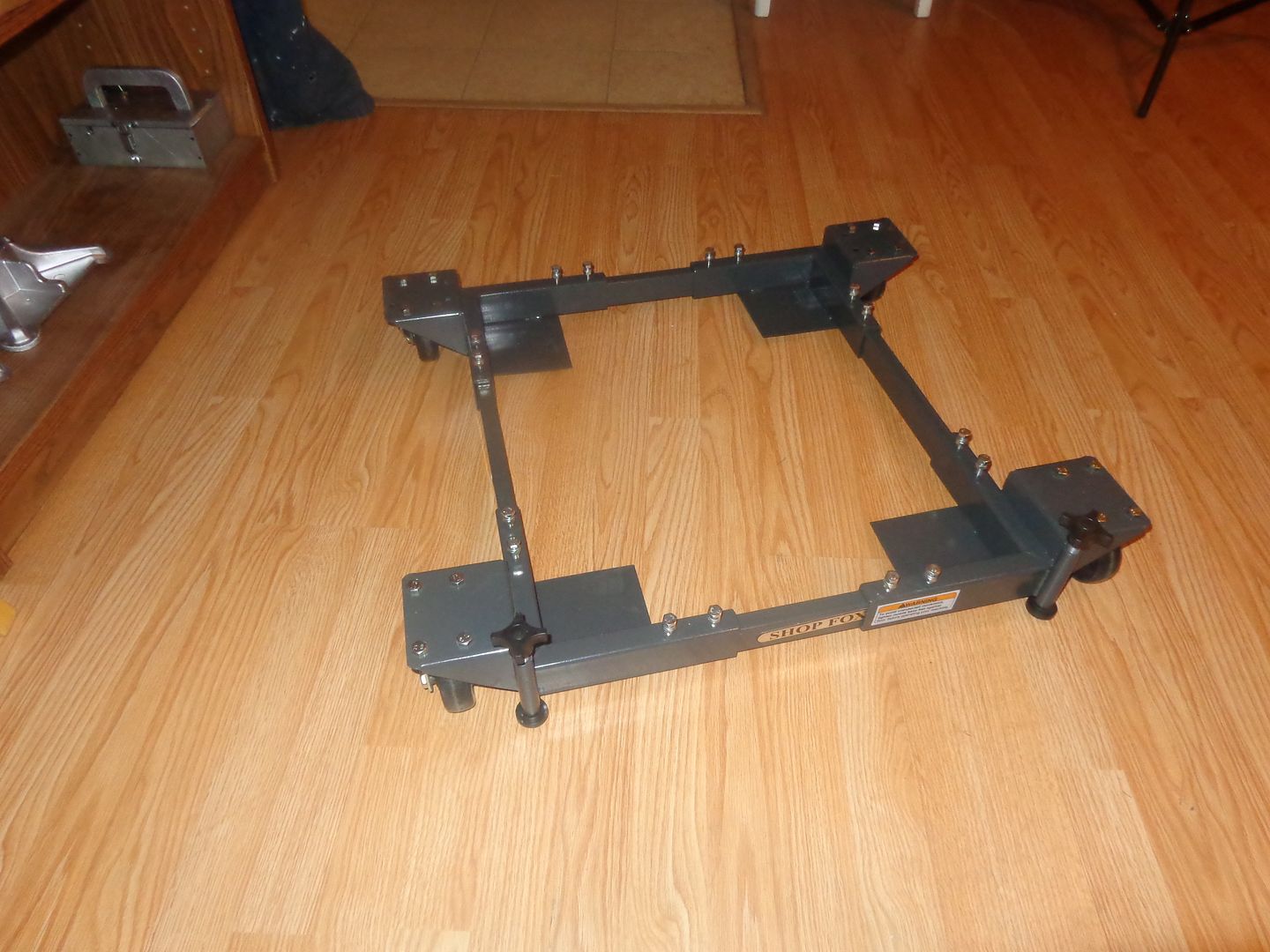
The big move is about to commence. the bandsaw moves out to the main garage. The old mill moves out to the main garage until I can sell it, and the new mill moves into my machine shop. I went up to BusyBee this morning and bought a machinery moving dolly, and I must say I am rather impressed. I don't think I would recommend it for moving a Bridgeport around on, but for machinery in the "under 700 pound" category, I think it's just the "cats meow!!!" All the other men I know are old farts like me, and I have two big strong sons, but one lives in a far off city and the other one is sick.-----So---This move will be a "Brian by himself move" as is generally the case. i think this little "cart" is going to be a real asset.
 
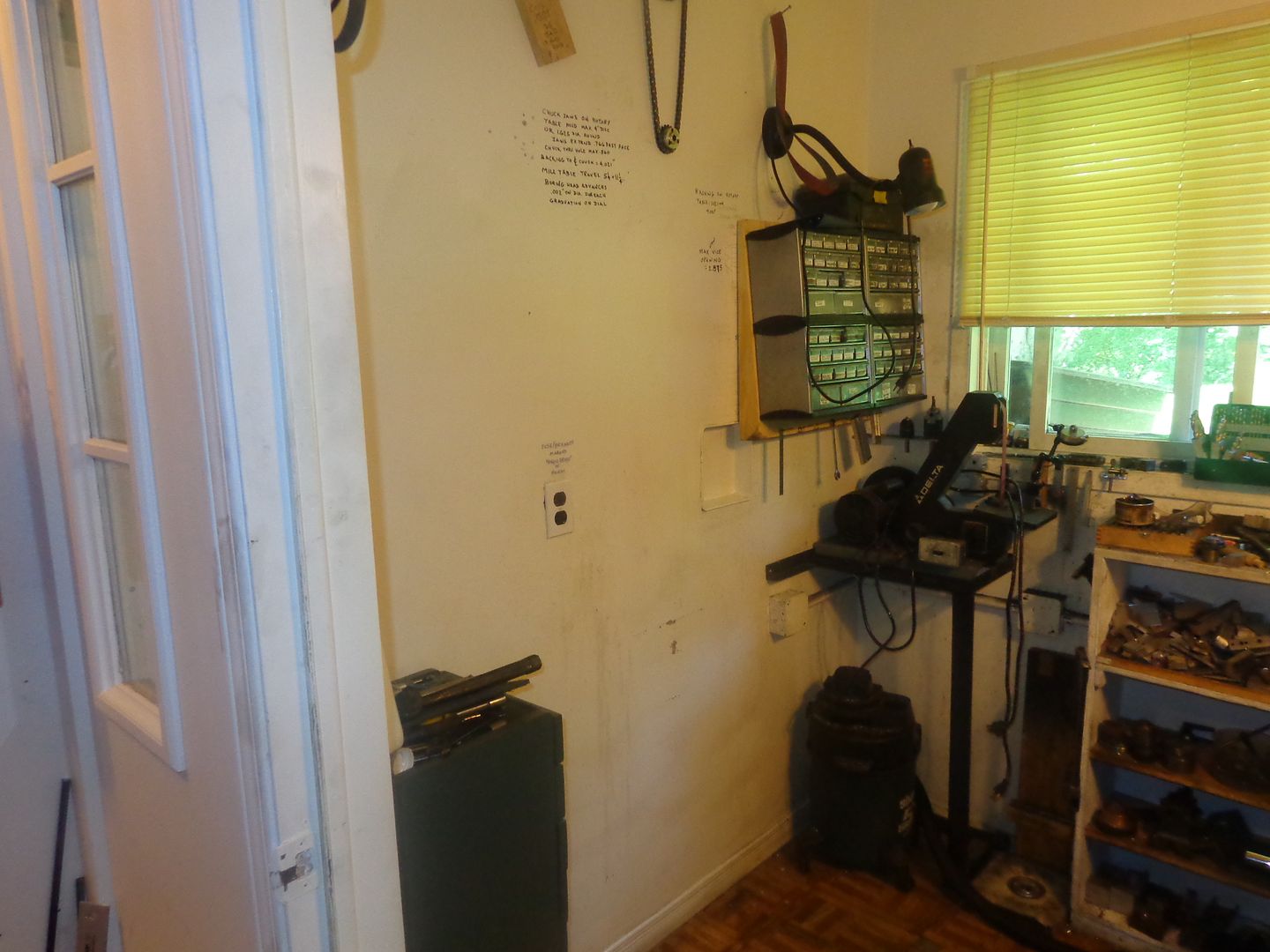
And so, my lads, we have the "Naked Machine Shop". The machinery moving cart worked marvelously, as advertised. The bandsaw and old mill are both out in the main garage. No tipped machinery, no mashed fingers, not even a tense moment really. Just very, very slowly and carefully, like porcupines making love!! I even washed 5 or 6 years of accumulated crud off the wall behind the mill!! Tomorrow I will do a big clean-up on the old mill and get it ready to advertise for sale. I don't want to move the new mill into place until I get this DRO business resolved, because the mill sets up against a wall in it's final position and I think I may have to drill and tap something on the back side of the carriage to hold a scale.---Much easier to do before I move it from the garage, where it has access all around it.
 
Well guys, that went quickly. Two hours ago I listed my old mill and tooling for sale , and a guy just paid cash for it and said, "Keep it here until I can arrange to pick it up!!" DRO here I come----Brian
 
Last edited:
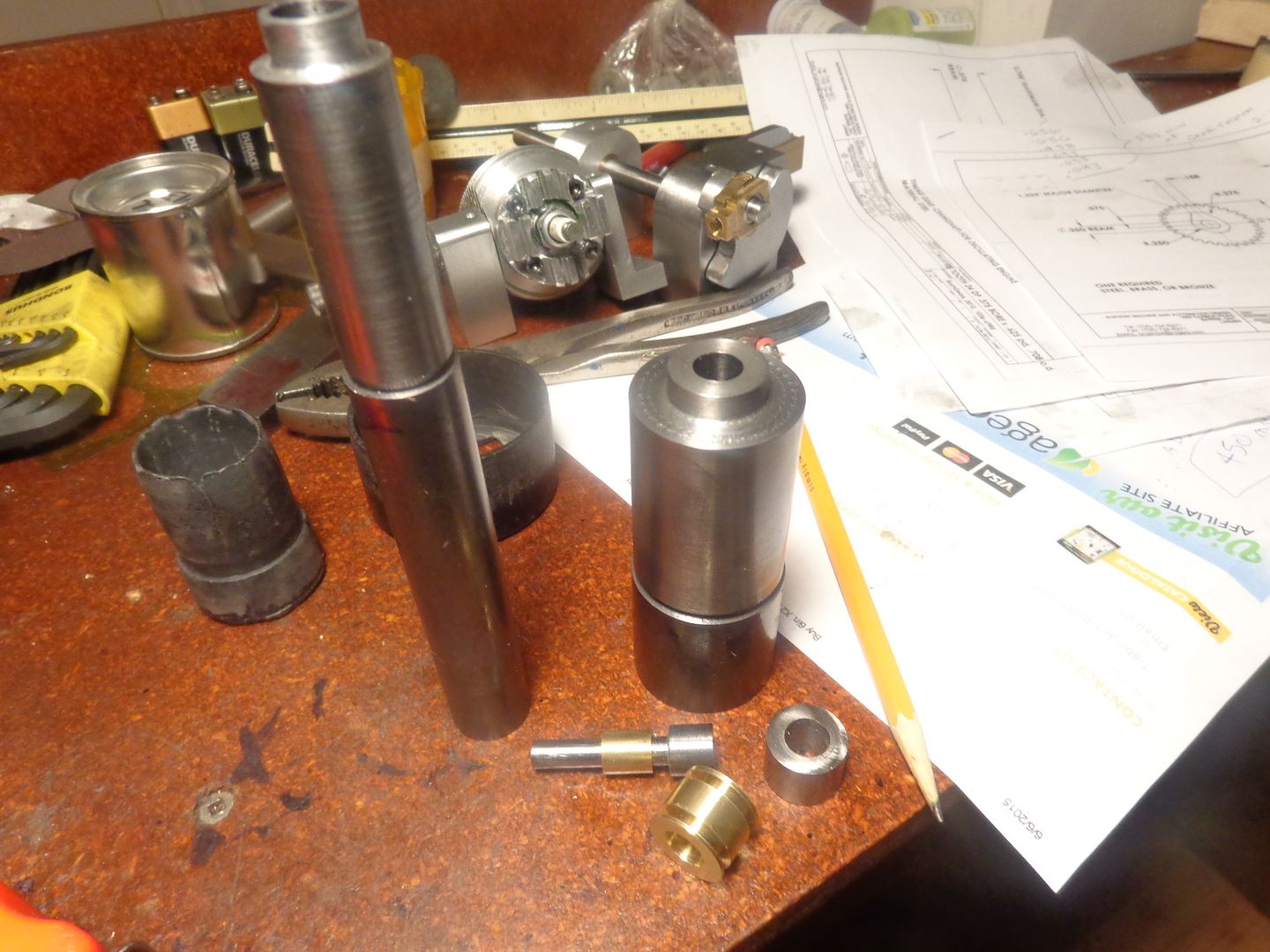
I actually managed to have a free morning at home today, so I thought I had better do something to keep this engine thread alive. I won't have access to a mill until my DRO's arrive and are installed, so I decided I would make as many round parts as I could on the lathe. I have turned and bored the blanks which will become my timing gears, plus enough extra gears to help out some poor fellow in USA who got my Rupnow Engine-2 three quarters built and then found out you can not purchase these particular gears---you have to make them!!! I also made the cam shaft, the bushing which presses into the cam gear, the ignition cam and the governor spool.
 
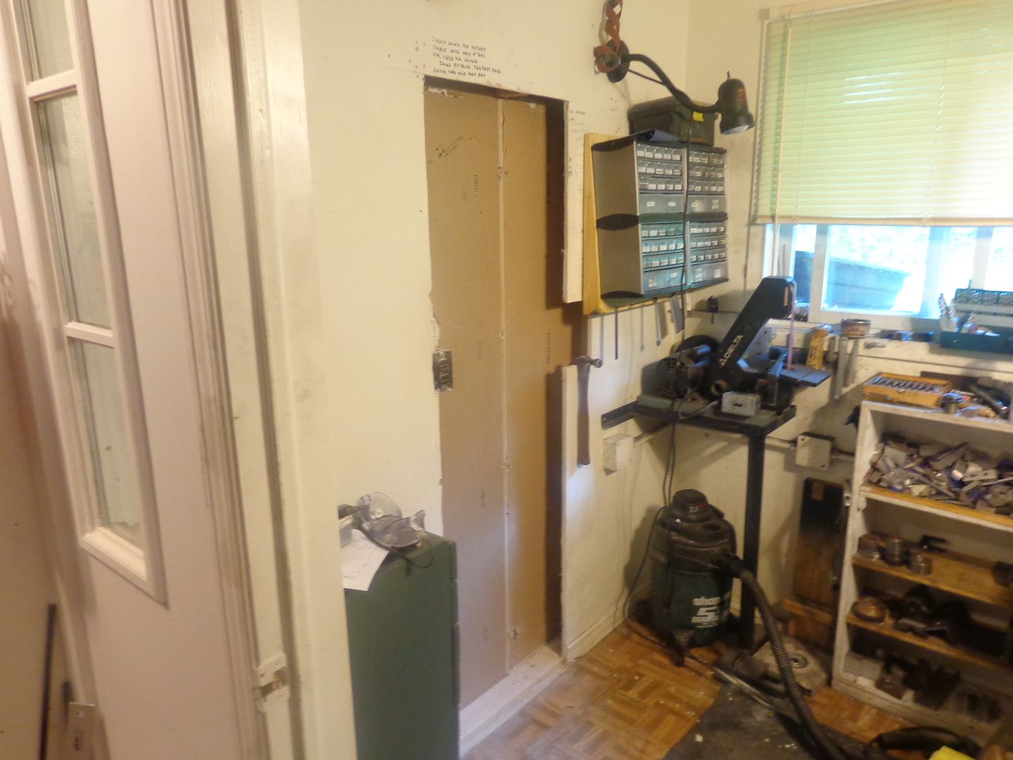
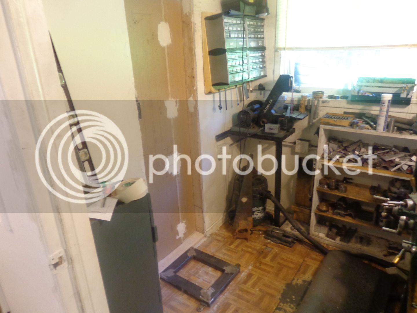
I am now a card carrying member of the infamous "Hole in the Wall Gang"!!! The new mill was about 4" thicker through than the old CT129 mill, and I couldn't afford the amount it would have protruded into my work space between the lathe and the mill. I will gain my 4" back by cutting a hole as shown The hole doesn't protrude into the adjoining room (which is just storage space anyways.) I gained back my 4" of space because the drywall was 1/2" thick and the "2 x 4" is actually 3 1/2" thick. I didn't cut through the bottom "footer" of the wall, because I didn't want to mess with the structural integrity of the wall itself. I will build a 1 1/2" thick x 3" wide rectangular steel tubing spacer to go under the front and two sides of the mill stand, and the back side of the stand will rest on top of that "footer". I still have to frame in the top and one side of the opening with 2 x 4's, and do a bit of trimming and plastering. I will have that finished by the time my DRO kit gets here.
 
Last edited:
Like the idea Brian.I am an expert on using every additional inch of available space.I have built lots of bookshelves by removing the front panel of plasterboard and setting the shelves into the wall.The shelves are sized to suit
paperbacks and only project 50mm Can you remove another section between vertical studs and make some useful storage shelving ? Regards barry
 
Nice work Baz. I am not a good 'finish' carpenter by any stretch of the imagination, but I'm great at framing and drywall work.--especially in the machine shop, where it doesn't have to meet too many critical eyes except my own.---Brian
 
For all you Canadians out there, who might consider buying this CX601 mill from BusyBee tools--A word of caution!! My old CT129 mill was set up so that each increment on the X and Y dials was .002" of table travel, and one full turn of a dial moved the table an exact 0.100". This made for a very easy mental calculation to determine how far you moved the table in either the X or Y axis. For some unknown reason, this new mill is .0025" movement for each graduation, and the table moves an exact 0.125" for one full turn. I checked this with a dial indicator, and it is correct.----This moves things into the realm of impossibility to do any kind of mental calculation of how many full turns and graduated marks you must turn the dials to move a given distance.----So---If you buy this mill, be prepared to use a calculator to figure out every move of the mill table, or shell out close to $1000 for a two axis DRO set-up. In my opinion, this is just about the stupidest thing I have ever seen. Caveat Emptor!!! (Buyer Beware.) If I had known about this before I bought the mill and got it home, I wouldn't have bought this particular mill.
 
Last edited:
This is very strange. .150 advance per turn is a 6.6666 thread per inch. I do not believe anyone made such a thread. But .15 inch is 3.81 mm and that is also a very strange pitch.

However 4mm is .157 inches, so if you are making a .007 error in your dial measurement then you have a 4 mm metric thread.

You really need a good DRO to use this thing.
 
Hi Brian, I have the same problem on my mini mill. It's set at .0625 for 1 full turn, But over time I have adapted. With zero setting circles you can still do the math in your head, it just takes a little longer. BTW you are making great progress on the engine. Everything looks really good.
 
I'm really not looking for the sympathy vote here. After six years of milling only using the dials, I was beginning to wonder just how nice it would be to have a DRO set-up, but simply don't do enough "for pay" milling to justify the expense. Fortunately, I have had two steady months of engineering design work, which pays for the mill and accessories. I have sold the old mill and a bunch of other tools which I no longer use, and that has pretty well covered the cost of the DRO set I have on order. I do use my lathe and mill for quite a bit of prototype work for some of my customers, but it is all very "hush-hush" stuff. I think it is a good milling machine. It is very robustly built, and has a whopping great 8 1/2" travel in Y axis and 23 1/2" in the X axis travel. It's just that I really resent being forced into buying a DRO kit because of the way the dials are set up.---Brian
 
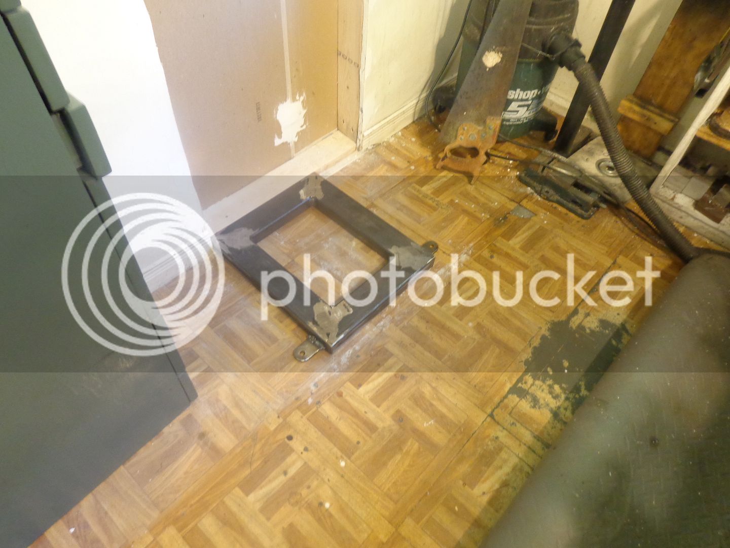
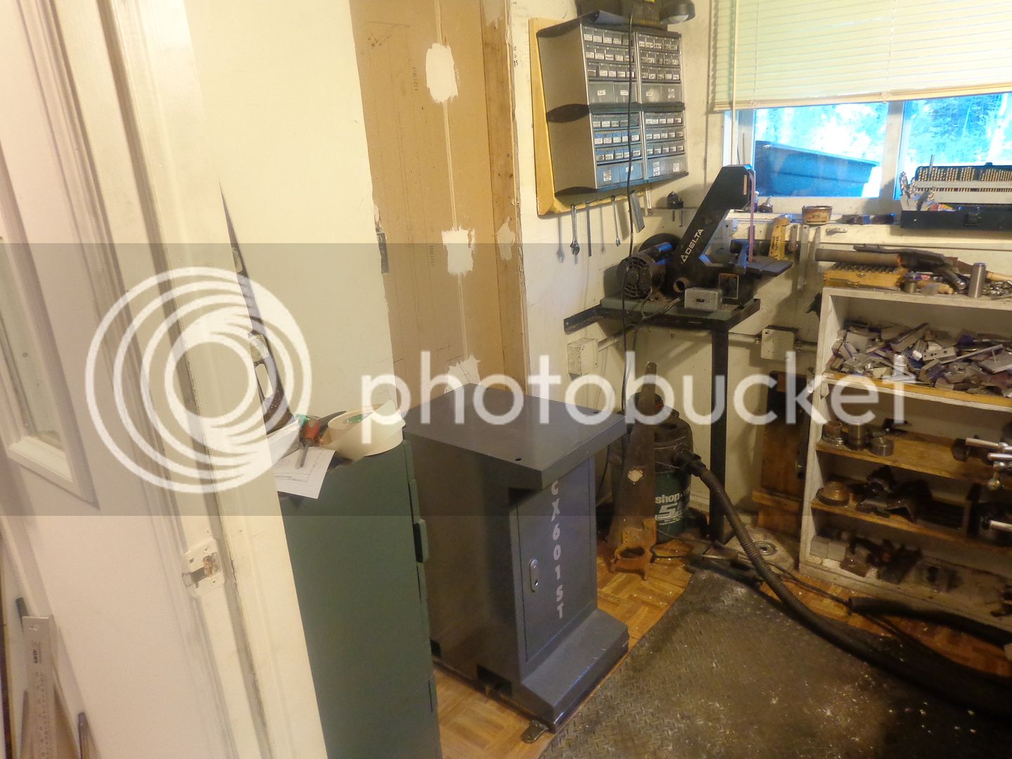
Things are going well with the milling machine installation. I have finished framing in the hole in the wall, and fabricated a welded sub base which is 1 1/2" thick, and exactly 3 1/2" shorter than the milling machine support cabinet base. The cabinet/base will set on top of the base and on top of the bottom "2 x 4" at the bottom of the wall. (A 2 x 4 is actually 1 1/2" x 3 1/2"). the two "ears" sticking out from near the front of the welded base will eventually be lag bolted into the concrete floor. The cabinet/base will set right up tight to the near side of the opening in the wall, and be lag screwed to the vertical 2 x 4 which forms one side of the opening. The opening in the wall is about 7" wider than the cabinet/base, so I may frame things in a bit more and screw the other side of the cabinet/base to the other side too---jury is still out on that. The welded sub base will be bolted solidly to the cabinet/base before the mill and cabinet/base are moved into place. The 1 1/2" thick welded sub base is made from hollow rectangular tubing, so I will drill large clearance holes in the side closest to the floor and smaller holes through the top side for 5/16" bolts which will pass through drilled holes into the underside of the cabinet/base.

 
And that, my friends, is a beautiful thing!! Everything so far is going according to plan. I have to drill a few holes in the side of the cabinet to attach it to the stud beside it to give the stand some more stability. (These China stands are sufficient to hold up the mill, but they are pretty damned wobbly when you have a 500 pound mill setting on top of them)---to say nothing of top heavy. I don't want my epitaph to read "Here lies Brian, crushed to death by his own milling machine that toppled over on him!!" :eek::eek:The only comment I have on this work so far, is that the steel in the base of those China stands is harder than the Devil's horn. It appears to be made from the same material as old bed rails that I have "re-claimed" for projects. I almost gave myself a hernia drilling eight 5/16" holes thru the base to attach my welded sub base. I have to disassemble everything and paint my welded sub-base with grey Tremclad (rust resistant) paint.
 
Good work Brian,i get a lot of pleasure from this sort of work,and as soon as your done you find further improvements.Those storage drawers to the right look as though they are just waiting to be recessed in the wall ? When your tight for space the things you do
 

Latest posts

Back
Top