I have had an old Herbert surface grinder for many years, and it has done sterling service over the years, easily achieving 0.0002" accuracy most of the time.
There has been one major problem with it over the years though, it only has a 7" x 4" stroke, limiting the size of jobs I could carry out.
So a new basic machine was ordered and was delivered about a month ago. This one will give me a grind size of 12" x 6"
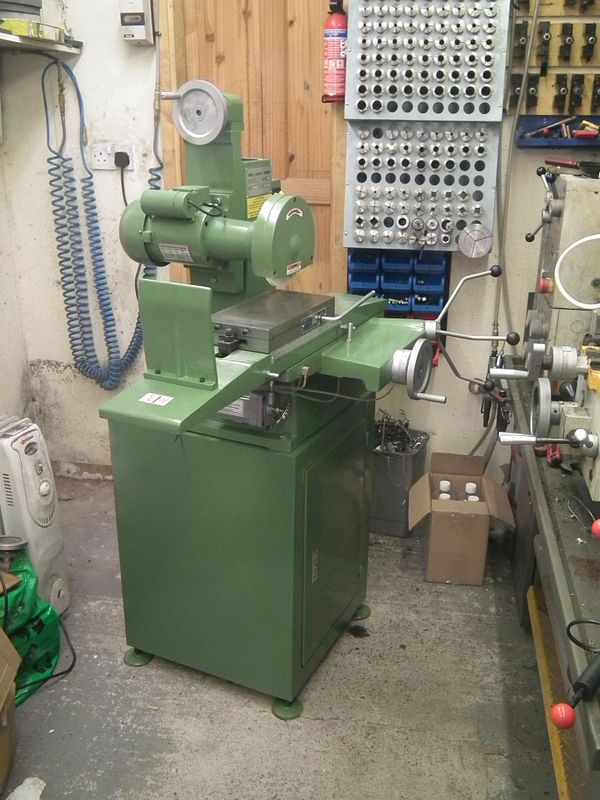
I had major trouble getting this machine into my shop. The stand was no trouble, but the main casting, minus the removeable table, came in at around 400kgs (about 800 lbs).
I had thought of all ways to get this up the steps and through my shop, but manually moving it into the shop and onto the stand was the major problem.
Luckily John Stevenson came to the rescue will all the right kit to do the job, and it only took about 15 minutes. Having good friends really does pay off when you come across problems like this.
So now comes to the setup of the basic machine.
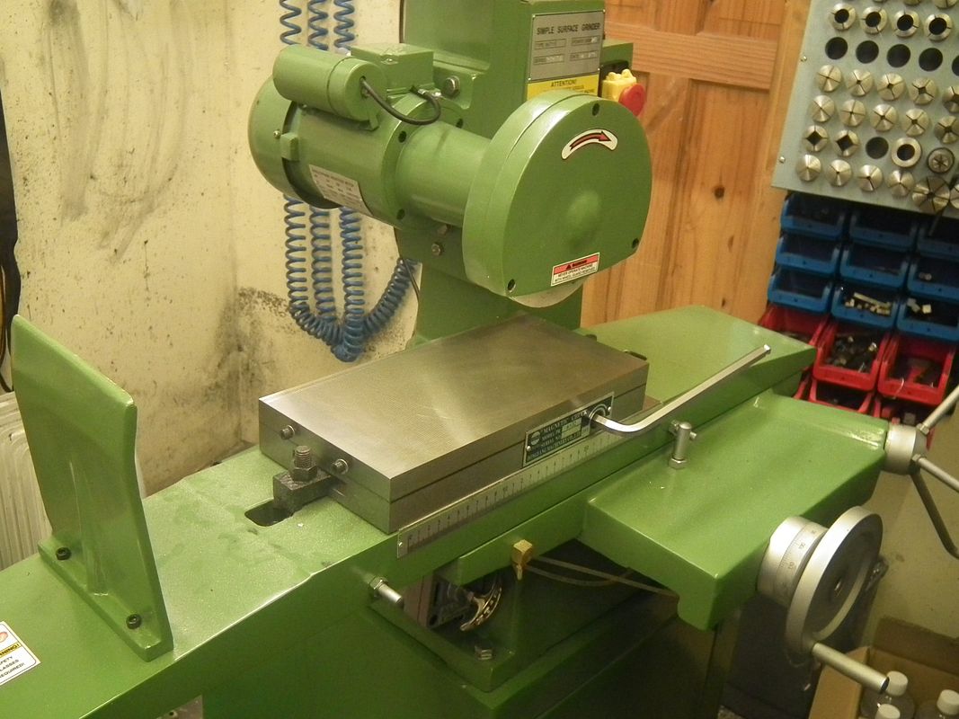
Firstly was to mount the magnetic chuck, getting it into the correct position and PERFECTLY in line with the stroke of the machine. That was really no problem with a 1/10ths clock and a very steady hand. Unfortunately this is when I found the first problem.
The reason you set the table up to the machine is so that you can use the built on side and end stops to get your job perfectly positioned. These stop strips were made from aluminium, not an ideal material, so one of the first jobs will be to make new ones from strip steel.
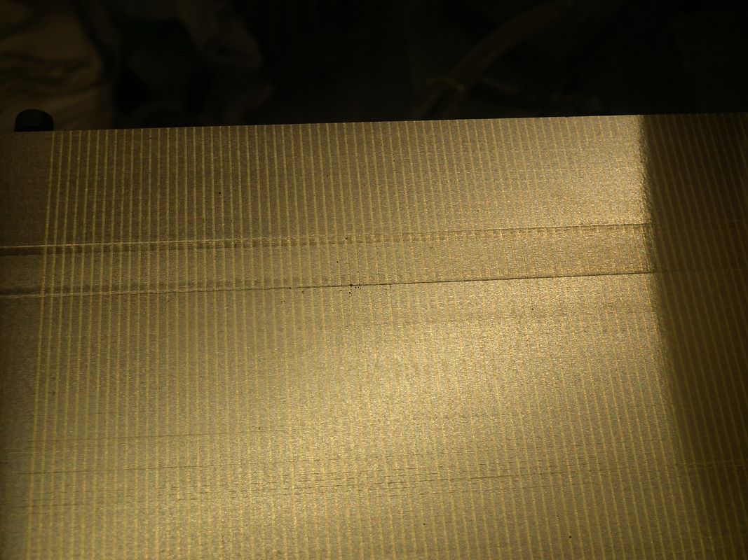
I can work without stops for the time being, but yet again, another job has to be done. The mag chuck needs to be faced all over so that anything placed on the table will be ground perfectly parallel to the face of the job that is down on the tables' surface.
But first, the wheel has to be balanced.
Luckily I had managed to pick up a balancing unit very cheaply.
So the wheel had to be dressed to get it running straight before using the balance, that was soon achieved with the supplied dressing stick and holder.
Then it is a matter of mounting the wheel holder onto a balancing mandrel, again supplied with the machine, then place it onto the knife edges on the previously levelled balancing unit.
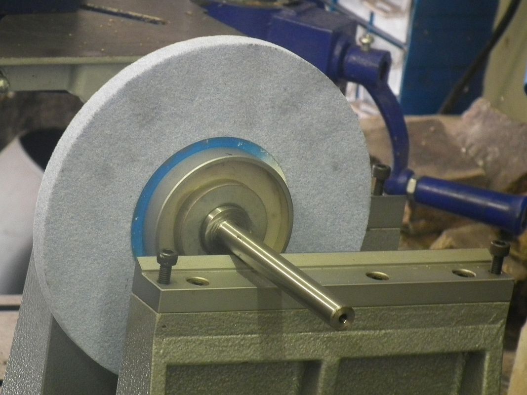
I ordered two extra wheel holders for a green and blue wheel as well as the normal white wheel. This one hasn't been fitted with balance weights just yet.
This one has, and five minutes later, the white wheel was perfectly in balance, having no heavy spots at all, just by positioning the balance weights in the correct positions. It is just a matter of practice. My old machine ran with no wheel balancing at all, no provision for it, and sometimes caused some bad effects on the ground surfaces, because of imbalance.
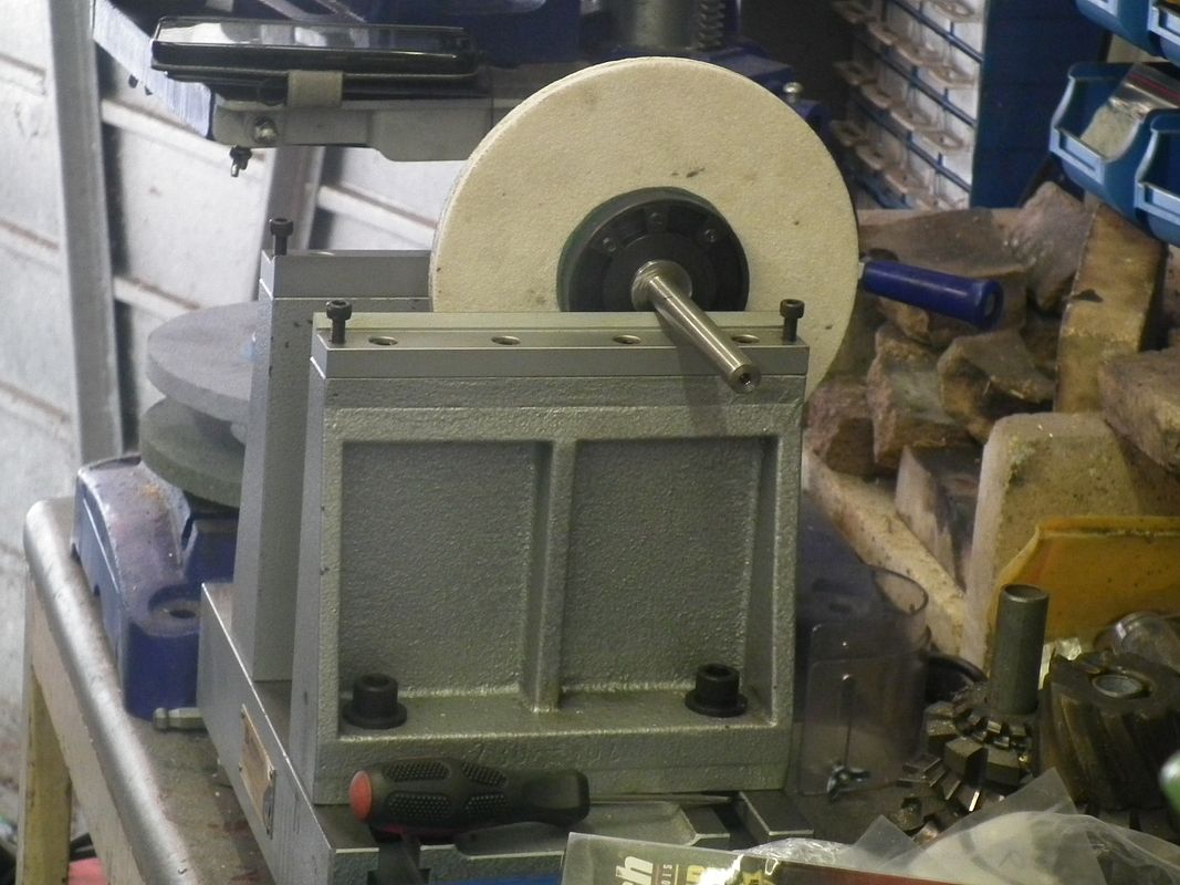
So the balanced wheel was fitted to the machine and I started to level the mag chuck.
The first run over got it level, leaving just a spark out over the surface to get it perfect.
Unfortunately, after a little while of doing the spark out, the grinding spindle dropped about 0.002", leaving a horrible groove across the table surface.
Not to be put off, I redid the table top, and on the second run it did the same thing, but not quite as deep.
Time for a bit of ass kicking at the suppliers.
Warco, from whom I had bought the machine couldn't come up with a simple answer other than annoying me stating that I had to go through the balancing routine first. After being told that I most probably had more experience than him with surface grinders (I used to do it in a production environment), he just shrugged his shoulders and left me to it.
So I really do need to sort this problem out before going much further.
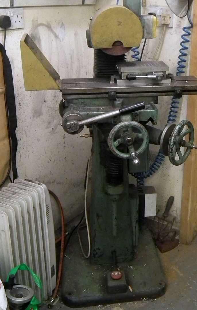
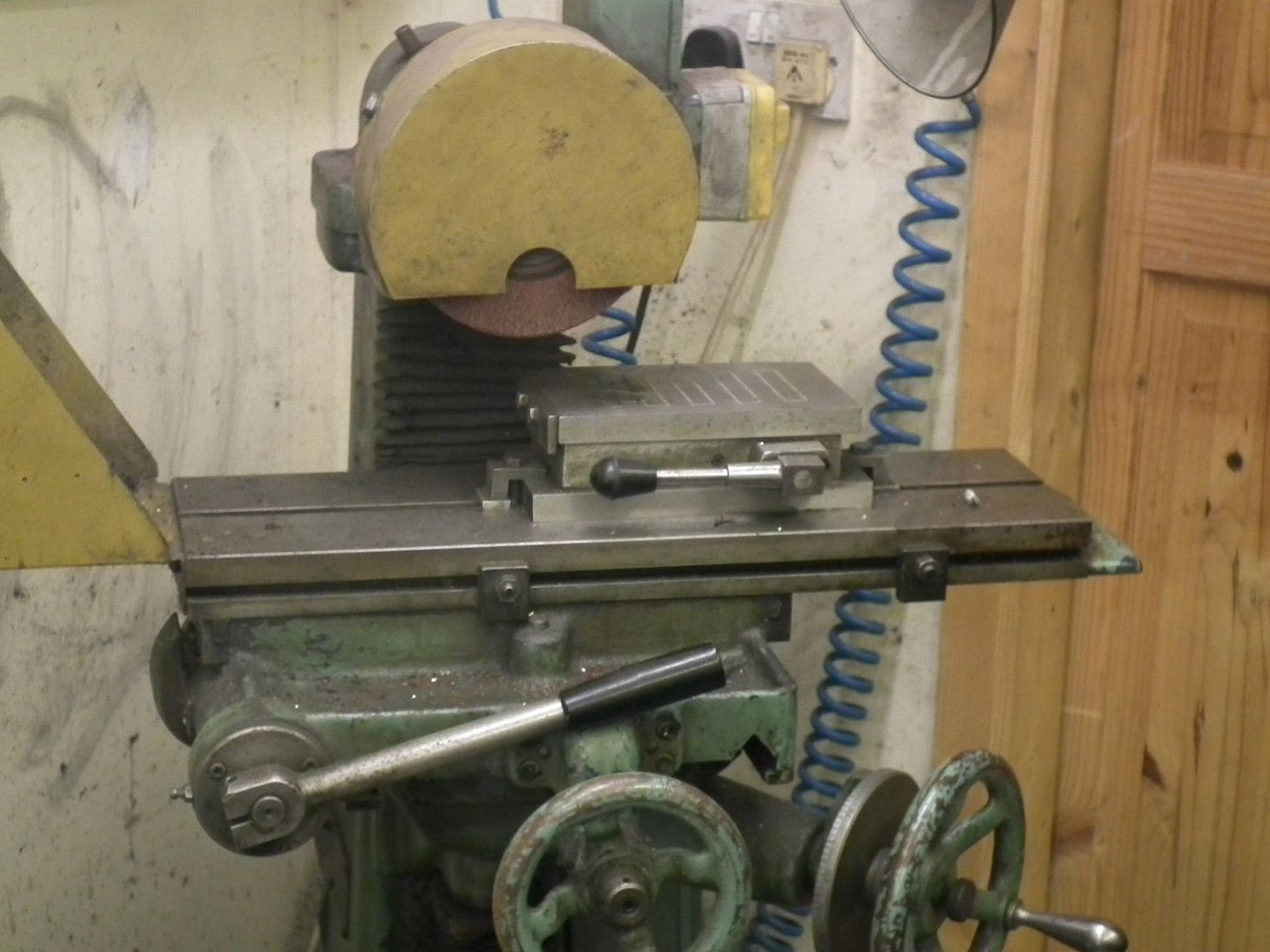
I suspected that it was something to do with the balance weight down in the bowels of the main casting, used to support and balance the spindle as it goes up and down.
In these two shots, I have already lifted the support cable up, the cable normally just runs over the top of the cross bar with the locking nut, not an ideal situation, as the tension would be variable as it was metal to metal friction rubbing, plus also it could move from side to side.
I have come to the conclusion that the rough face of the balance weight is catching on the even rougher face of the column insides, so causing the hanging up and sudden release.
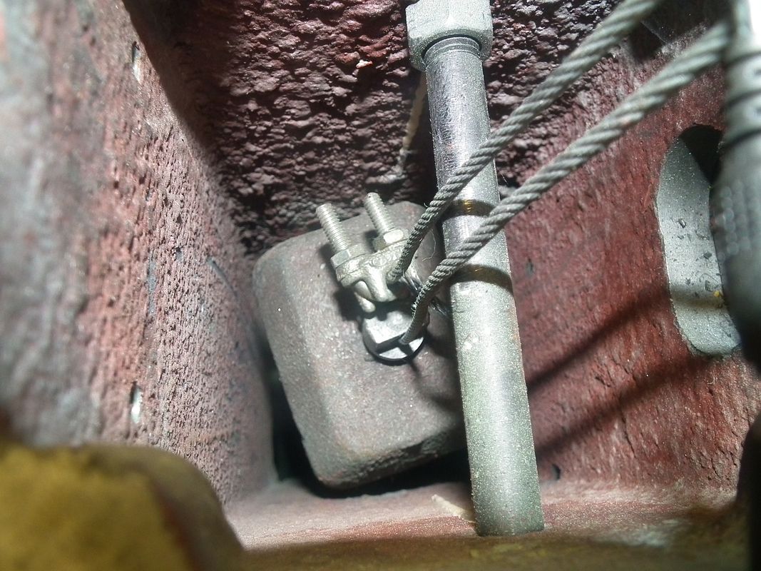
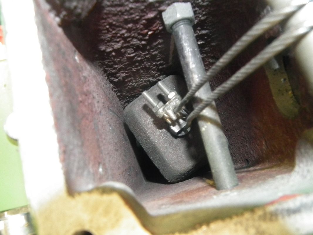
So after a bit of further exploration I have decided to swing the weight around slightly on it's lifting eye, so that it is more square to the column insides and make a roller for the cable to run over, so that it can't move side to side.
So that is as far as I have got with it at this time, so watch this space to see if I fall flat on my face. Unfortunately, I have to wait for my mate to come over to lift the weight out for me before I can proceed further.
Luckily, I have a bit more to show you before I had the machine moved into my shop.
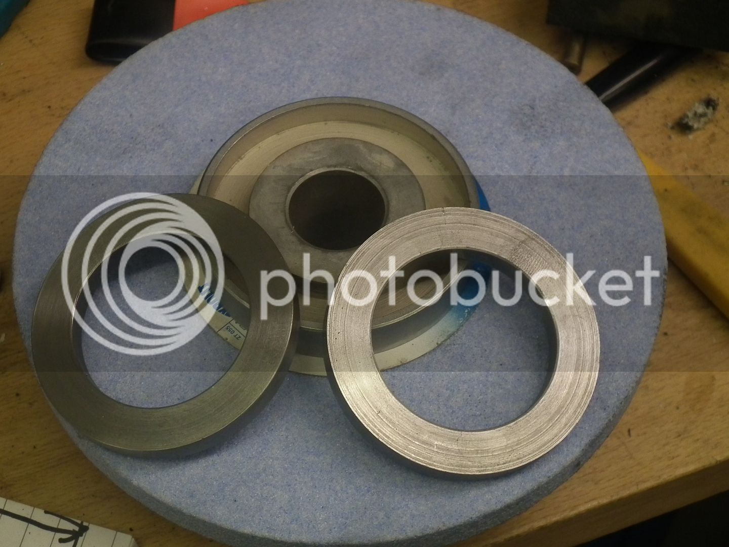
As I said earlier, I had bought a couple of special wheels that should cope with 99% of what I want to do, and I had ordered a couple of machine holders for these wheels. Unfortunately, they are not supplied with balance weights, so I have already got through some of the making process.
Grabbed hold of a bit of rough stuff from the scrap box and turned the OD required (measured up from the wheel holders).
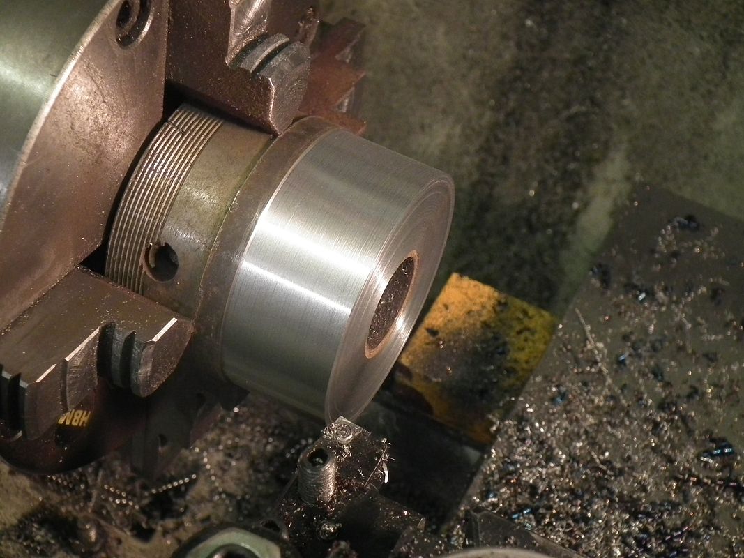
Then bored the ID.
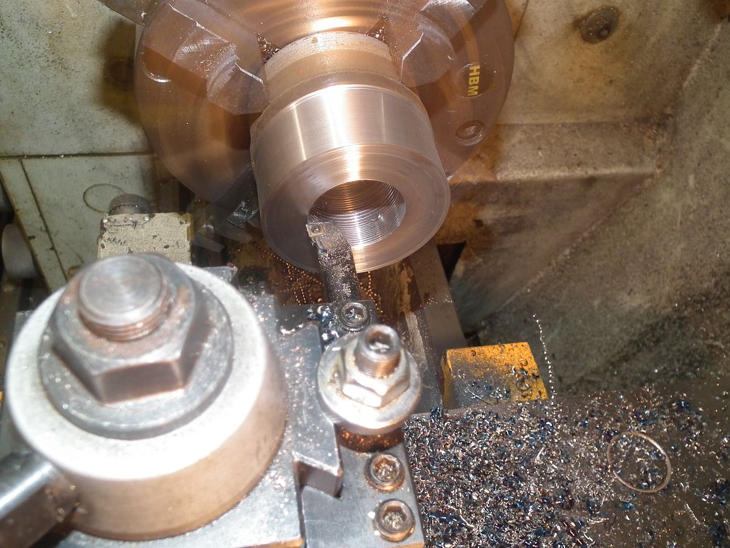
Followed up by parting off the disk.
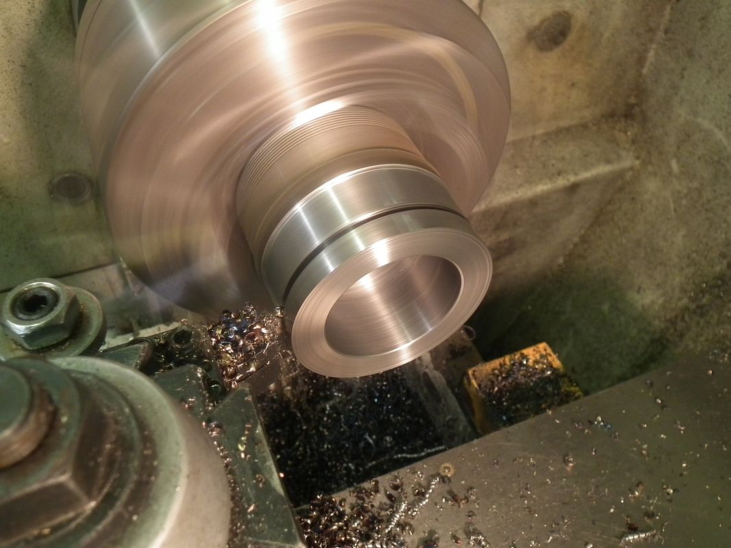
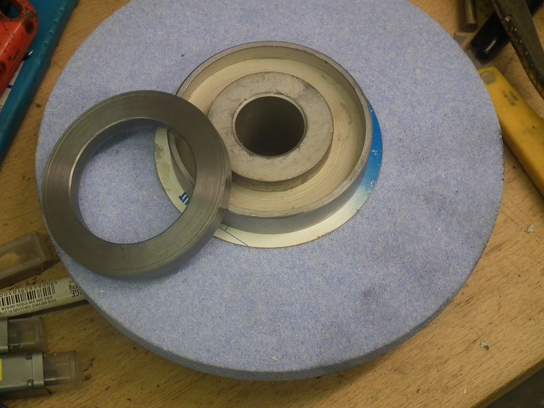
It fits just right
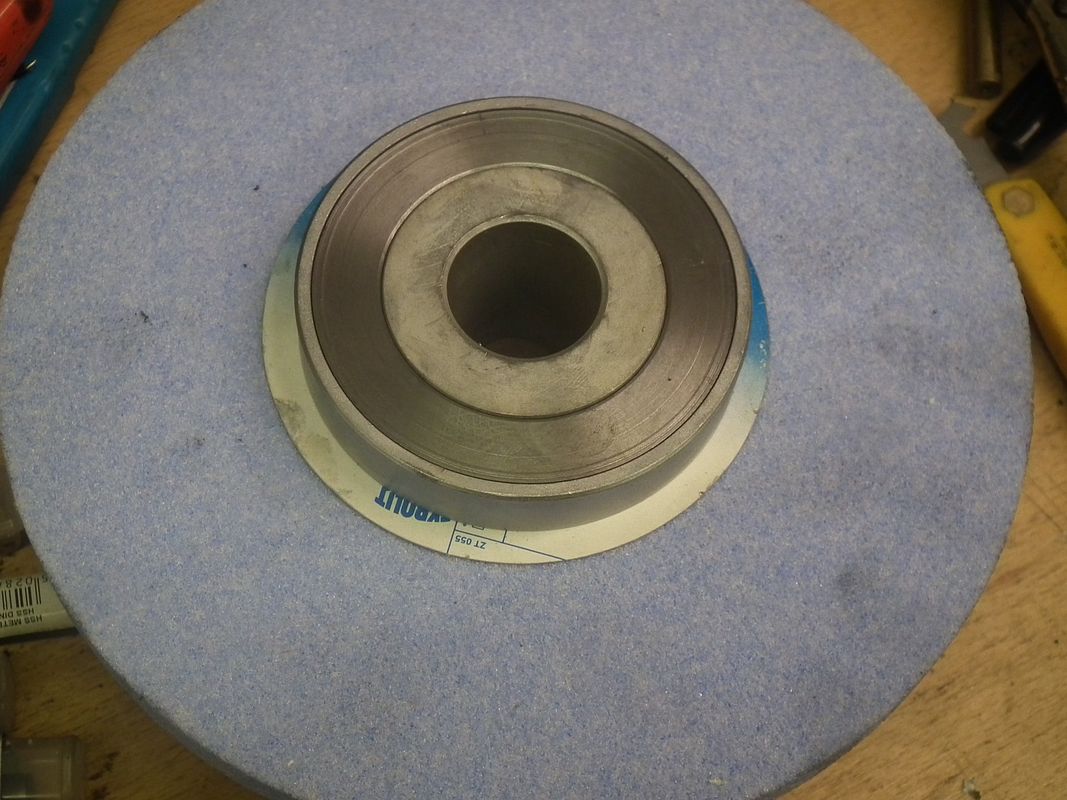
You never know, I might need a few extra over time, so I made two.
After putting on a marking coat, using a round bar centre finder, I roughly marked out the segments I require. They don't need to be exactly the same, something near enough will do just fine.
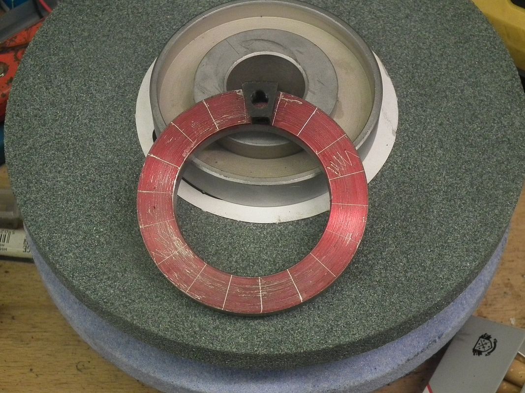
It was just a matter of getting the two opposing lines parallel with the vice jaws and making the cut.
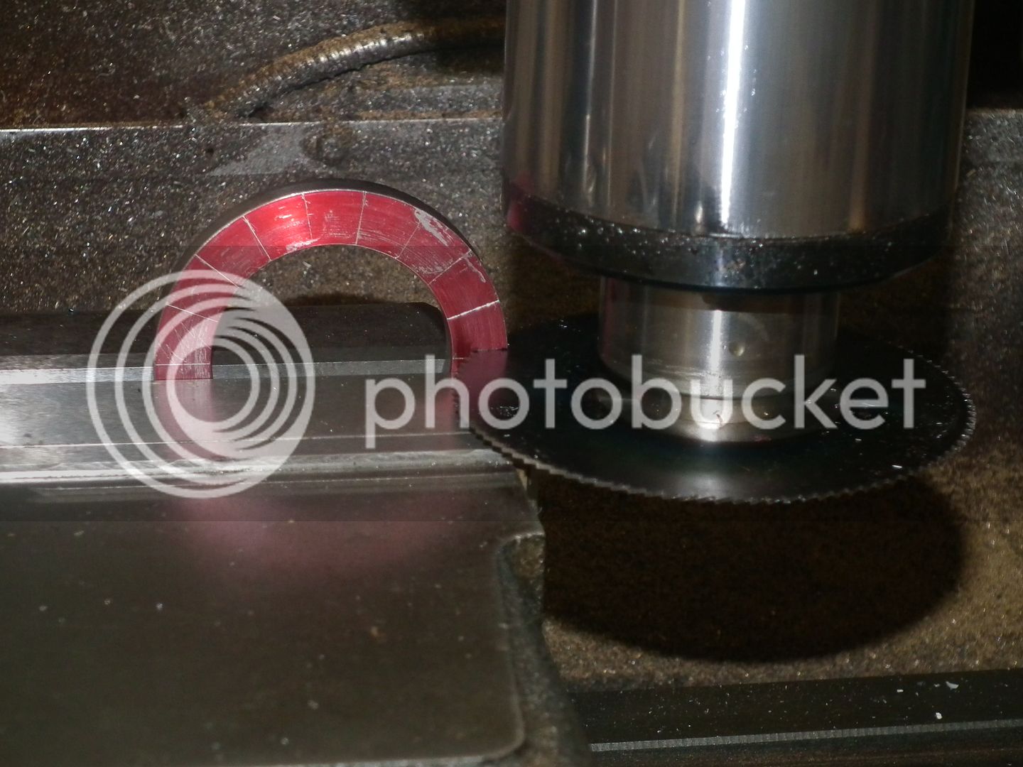
But not cutting all the way through.
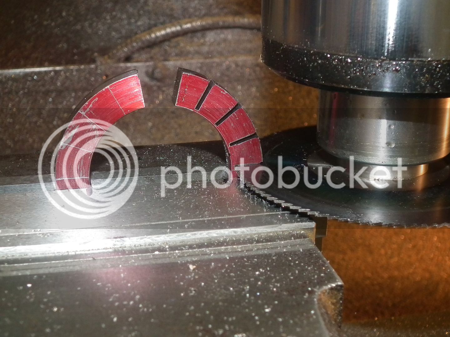
Then just snap them off, the second pic shows how many I made.
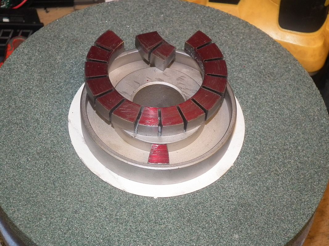
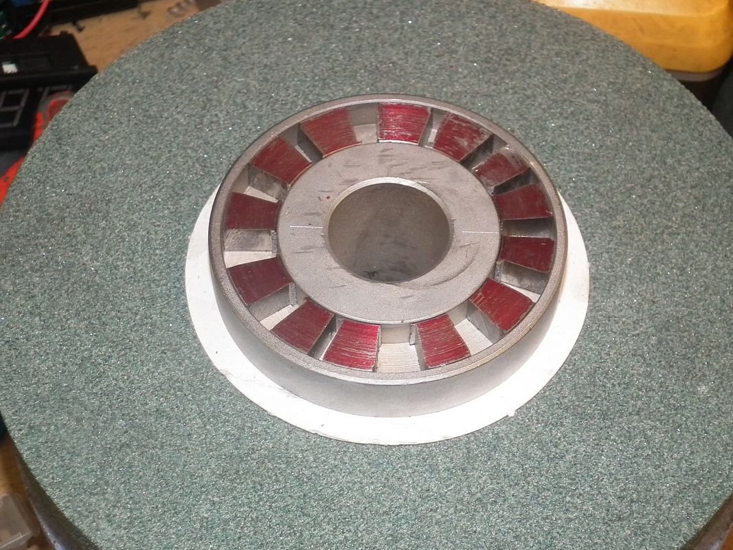
This is another job that requires finishing off, dressing, drilling and fitting a grub screw and ball bearing, but the machine fix must come first.
To Be Continued.
John
There has been one major problem with it over the years though, it only has a 7" x 4" stroke, limiting the size of jobs I could carry out.
So a new basic machine was ordered and was delivered about a month ago. This one will give me a grind size of 12" x 6"
I had major trouble getting this machine into my shop. The stand was no trouble, but the main casting, minus the removeable table, came in at around 400kgs (about 800 lbs).
I had thought of all ways to get this up the steps and through my shop, but manually moving it into the shop and onto the stand was the major problem.
Luckily John Stevenson came to the rescue will all the right kit to do the job, and it only took about 15 minutes. Having good friends really does pay off when you come across problems like this.
So now comes to the setup of the basic machine.
Firstly was to mount the magnetic chuck, getting it into the correct position and PERFECTLY in line with the stroke of the machine. That was really no problem with a 1/10ths clock and a very steady hand. Unfortunately this is when I found the first problem.
The reason you set the table up to the machine is so that you can use the built on side and end stops to get your job perfectly positioned. These stop strips were made from aluminium, not an ideal material, so one of the first jobs will be to make new ones from strip steel.
I can work without stops for the time being, but yet again, another job has to be done. The mag chuck needs to be faced all over so that anything placed on the table will be ground perfectly parallel to the face of the job that is down on the tables' surface.
But first, the wheel has to be balanced.
Luckily I had managed to pick up a balancing unit very cheaply.
So the wheel had to be dressed to get it running straight before using the balance, that was soon achieved with the supplied dressing stick and holder.
Then it is a matter of mounting the wheel holder onto a balancing mandrel, again supplied with the machine, then place it onto the knife edges on the previously levelled balancing unit.
I ordered two extra wheel holders for a green and blue wheel as well as the normal white wheel. This one hasn't been fitted with balance weights just yet.
This one has, and five minutes later, the white wheel was perfectly in balance, having no heavy spots at all, just by positioning the balance weights in the correct positions. It is just a matter of practice. My old machine ran with no wheel balancing at all, no provision for it, and sometimes caused some bad effects on the ground surfaces, because of imbalance.
So the balanced wheel was fitted to the machine and I started to level the mag chuck.
The first run over got it level, leaving just a spark out over the surface to get it perfect.
Unfortunately, after a little while of doing the spark out, the grinding spindle dropped about 0.002", leaving a horrible groove across the table surface.
Not to be put off, I redid the table top, and on the second run it did the same thing, but not quite as deep.
Time for a bit of ass kicking at the suppliers.
Warco, from whom I had bought the machine couldn't come up with a simple answer other than annoying me stating that I had to go through the balancing routine first. After being told that I most probably had more experience than him with surface grinders (I used to do it in a production environment), he just shrugged his shoulders and left me to it.
So I really do need to sort this problem out before going much further.
I suspected that it was something to do with the balance weight down in the bowels of the main casting, used to support and balance the spindle as it goes up and down.
In these two shots, I have already lifted the support cable up, the cable normally just runs over the top of the cross bar with the locking nut, not an ideal situation, as the tension would be variable as it was metal to metal friction rubbing, plus also it could move from side to side.
I have come to the conclusion that the rough face of the balance weight is catching on the even rougher face of the column insides, so causing the hanging up and sudden release.
So after a bit of further exploration I have decided to swing the weight around slightly on it's lifting eye, so that it is more square to the column insides and make a roller for the cable to run over, so that it can't move side to side.
So that is as far as I have got with it at this time, so watch this space to see if I fall flat on my face. Unfortunately, I have to wait for my mate to come over to lift the weight out for me before I can proceed further.
Luckily, I have a bit more to show you before I had the machine moved into my shop.
As I said earlier, I had bought a couple of special wheels that should cope with 99% of what I want to do, and I had ordered a couple of machine holders for these wheels. Unfortunately, they are not supplied with balance weights, so I have already got through some of the making process.
Grabbed hold of a bit of rough stuff from the scrap box and turned the OD required (measured up from the wheel holders).
Then bored the ID.
Followed up by parting off the disk.
It fits just right
You never know, I might need a few extra over time, so I made two.
After putting on a marking coat, using a round bar centre finder, I roughly marked out the segments I require. They don't need to be exactly the same, something near enough will do just fine.
It was just a matter of getting the two opposing lines parallel with the vice jaws and making the cut.
But not cutting all the way through.
Then just snap them off, the second pic shows how many I made.
This is another job that requires finishing off, dressing, drilling and fitting a grub screw and ball bearing, but the machine fix must come first.
To Be Continued.
John


![DreamPlan Home Design and Landscaping Software Free for Windows [PC Download]](https://m.media-amazon.com/images/I/51kvZH2dVLL._SL500_.jpg)


")