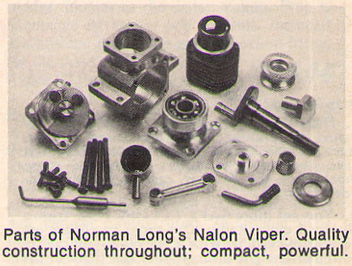
Nalon Viper 2.5cc CI Engine

Home Model Engine Machinist Forum

Help Support Home Model Engine Machinist Forum:

This site may earn a commission from merchant affiliate links, including eBay, Amazon, and others.
That was exactly my point to the person who suggested this on the other forum. Not practical at all unless one can load the front outer ring in the opposite direction to the load on the inner - hence my thought that, as the crankshaft is acting as the spacer - which for all intents and purposes it is - then possibly a tough resilient compressible material acting in the other direction on the outer ring may, potentially, have this effect.

I am not suggesting that this is the road to take - merely that it has a potential. The twin ball race engines made so far plus those odd commercial ones renovated (twenty plus) have all been set up as previously described with a very small clearance behind the front bearing.

The bearing fit on all is very smooth and free - obviously an important requirement - That they have all run and run well is all I can say to qualify my reasoning.

Tug
 
@Ramon You could use a wavy washer to spring-load the thing. Or maybe a really skinny Belleville washer. Even once you're past the need for it to be custom-made, I can see all sorts of difficulties with getting the material and temper right so that it stands up under heat cycling and vibration, but you could try.

@Peter Twissell : From my understanding of how the whole preload thing works, you could space the outers out and the inners in, instead of the other way around, so Tug's notion of an O-ring would work for as long as the thing had some spring.

And, having worked in aerospace, I know there's some guy in the corner with an advanced degree and no concept of practical application who's thinking that if you make the case out of the same material as the crank, then the case and the crank together could be precision ground (or shimmed) to provide the right preload. Never mind wear and thermal effects -- they'd convince the boss that it'll work, and if they've also got political chops the thing will actually get into production before people realize that it doesn't work over temperature.
 
Hello Tim, yes I guess a strong narrow banded wavy washer would work but my thinking on this is only just that - a thought. I'm pleased to see you refer to it as a notion :)

So many engines have been set up 'the other way' I feel there's little to be gained in trying. If it was a really viable proposition then I'm sure it would have been done by many of the high performance engine manufacturers long before now which was the thrust of my reply to the original poster on the other forum.

The main object is to get the lower end as true as possible - bearings exactly concentric and parallel to each other with no hint of stresses to inhibit a truly free running shaft in the slightest. It's easy enough to achieve with home based kit but we'll leave that until Patrick gets there. He's got that case to make a start on first;)

Tug
 
Steel housings have been used successfully in many competition engines. As well as aluminum bearing spacers on the inner races. It's a very complicated application.

Bearing axial clearance is part of the design with the rest of the components to provide acceptable clearance. Production sport (not competition) engines will not be critical of this. In all cases, bearing races must not slip in the housing, thus any axial clearance between outer races and the case is useless.

Theory is fun, but when these parts are made, if the bearings are found to bind upon assembly, a shim can be placed between the front bearing and crank shoulder. This was common practice in many production hobby engines. Recesses to prevent rubbing of the races is standard practice.

Hi 'DP' (Greg?)
Are you not meaning radial clearance as I cannot see why axial clearance would allow bearings to slip in their housings.

The effect of adding a shim is no different from having a crankshaft fractionally longer than the make up of the crankcase length between the rear of the front housing and the rear of the rear bearing fully seated.

This is not 'theory' but based on actual application over several builds of diesel engines half of which have been twin ball raced.

I don't dispute that much has beeen done to improve high end engines in high end useage and using superb machines with excellent measuring facilities but perhaps we need to consider something here.

This is trying to help someone who has just finished his first two small engines after quite some difficulty to get them to run. Fired with that success he has picked a design to follow up on what was designed as a racing design circa 1950 and is to be built on basic kit - something we shouldn't overlook, unless, that is, I'm missing something here

Regards - Tug
 
Last edited:
I think you hit the nail on the head there Ramon, this is the construction of a replica Naylon Viper. If someone wants to use it as a basis for their own modifications then that is another story. With most of them destined for a few bench runs and not likely to be mounted in an airframe any modification are unlikely to reap benifits.

It's a shame a few details were missed off of the drawing, whether that was Eric's measuring or when Ron drew it up. A quick look on Model Engine news will show the OP that there was a raised area for the inner race of the rear bearing to seat against if you look closely at the dismantled original. Also note the reduced diameter between bearings.

An alternative to adding shims as DP suggests would be to make the shaft a little longer and skim a bit off the face that the collet bears against to get the required fit on assembly.

648095.jpg
 
An alternative to adding shims as DP suggests would be to make the shaft a little longer and skim a bit off the face that the collet bears against to get the required fit on assembly.

Well that's exactly what I've been saying from the outset Jason but unless I'm not explaining myself very well it doesn't seem to have come across as such.

I think it would be very fair to say that in the world of home made engines none did those of us who do so better service than Ron Chernich on MEM. His interest in encouraging such has to my mind not been repeated since his passing. I don't know exactly when Ron drew out the Nalon but he was no doubt beginning to feel the effects of his illness. We all know - rather we all should know - that despite the best will in the world those who do drawings will inevitably omit something or, dare it be said, even make a mistake.

The Nalon is a great design - a bar stock engine well ahead of it's time and aimed primarilly for the team racing fraternity. I beleive that it's failure to make a mark was a business decision and nothing to do with the engine itself.

It makes for a very good home build project with, if made well, with a performence to boot no doubt but what it's being made on, what it's being measured with and what the skill of the builder is should always be kept firmly in mind - that is - in my opinion :)

Tug
 
Hi, and thanks again for the replies. I'll be making some swarf soon i promise so please bear with me as I'm going slow to go fast later (or probably slow by all your standards.

At the risk of doing this one 'to death', below is the CAD now taking into account what I think i've heard above by adding an 0.1mm bit of breathing space behind the front bearing.

The inner race of the front bearing is now drawn tight between the step on the crankshaft shaft and the prop driver/cone and the rear bearing is pressed in tight against the front housing with a little bit of space so the inner race doesn't rub.

The prop should be pulling everything in the correct axial direction but the press fit should stop anything moving anyway. Worst case the bearings move in the wrong direction, 0.1mm should be easily absorbed by the float on the gudgeon pin up-top.

I think I understand it. Sorry of this is all so obvious. Promise some more action soon! :)

Patrick
Screenshot 2020-11-27 at 18.46.16.png
 
You are getting close Patrick ;)

Just make sure that the gap behind the rear race inner is nothing more than a scrape - literally a scrape. It needs to just pull the bearing together slightly before coming up tight - too much and you will have the same situation at the other end - crowding the rear race. If you are not sure of getting that right just make the face flat all over. Far better to have a small degree of float in the bearing than crowding it.

I've been reading the FMV story again - the last time was when it first appeared in Aeromodeller! They do indeed have a spacer as has been previously mentioned but are insistent that the two bearing inners are pulled tight together against that spacer - which brings it all round back to the beginning!

Tug
 
Just a couple of armchair comments to consider

- red arrow, this area looks a little thin for where a lot of forces congregate. Usually commercial 2S engines are quite meaty by comparison and typically even have an array of gussets integrated into the casting. Since you will be turning, might want to give yourself the benefit of more material. It might serve a similar purpose to give the carb throat more material to enter & reside in on the top side.

- green arrow. Usually the back side of the drive washer is flush with the end of the crank housing. Not sure if its for debris mitigation or aesthetics bu it just looks more right. Sometimes the front face of the DW is larger diameter to better fit a specific prop range, but that's up to you. Sometimes you see 2 threaded holes in the front face to use a puller rather than trying to grip on the radius area. Even when the fits are right, oils & such have a way of turning into an effective adhesive over time

- purple arrow. Not sure if this is an aberration of your cross section but the hole should go straight through?
 

Attachments

  • 2020-11-27_15-17-18.jpg
    2020-11-27_15-17-18.jpg
    41.5 KB
I had all this typed out yesterday, but dinner and all...

Of course you can design to allow the necessary clearance. The prints do not show this. Once the parts are made and there is a problem, the shim is the easy solution.

The ideal design would result in a specific end play (axial clearance) in the crankshaft at operating temperature. This is what appears to be strived for in competition engines. Theory referred mainly to the idea of attempting to preload bearings in a model engine.

To be honest, I have no idea what crowding refers to. Preload or the races rubbing the housing?

You wrote "There has to be some clearance behind that front bearing in it's housing otherwise binding will occur" This is not the case in any production engine I've measured. The outer races are always pressed to the bottom of the bore and interference fit so as not to move at operating temperature. If there is any chance for movement, it will be the rear inner race on the shaft. And there is usually a clearance between the inner race and crank web. Further "The fit of the front bearing in it's housing is usually of less tolerance ie tightness, than the rear fitting.This allows the bearing slight movement as the shaft expands/contracts with temperature variation" I have never seen this in production. It may be terminology, I think you are referring to a slip fit of the out race vs the standard interference fit. The Nalon prints say both bearings are a press fit in the case.

In virtually all designs I've seen, both outer races are interference fit to the case, even at temperature and the front inner race is clamped to the shaft. Bearing radial clearance and axial spacing results in some endplay in the shaft. The shaft and case expand at different rates.

A: If the rear inner race is an interference fit, the shaft and bearing axial spacing is such that differential expansion still leaves desired clearance, no trouble. This is a typical race engine setup.

B: If the rear inner race is a clearance fit on the crank and there is room for movement, no trouble. This is typical sport engine setup. This allows looser production tolerance.

Going by the Nalon prints, it's line to line with no clearance between the rear inner race and web. I would add some and allow for a push fit.

I agree that the skill of the builder comes into play, but one can only build to the prints given. Following erroneous prints (regardless of the source), there is truly only one possible outcome. If we assume the skill level doesn't recognize the importance of the bearing assembly, the prints should include it. If we get into how to fix the prints, then there is a lot to be said about the how and why.

I've attached what I will do, eventually. Forgive the awkward prints as I work in metric and this is a clumsy combination of both. So far, I only have the front end drawn and don't know how the rest fits. The crank pin is in the same position as designed and there is plenty of clearance for the rod anyhow. The only other change is the outer races stand 0.2mm proud of the case and the housing flange is thicker.

Eh, sorry for so many words.

Greg
 

Attachments

  • NALON_VIPER_BRG_HSG.PDF
    62.6 KB
Petertha,

I was under the impression this was a 'concept' drawing to ascertain the layout as opposed to a drawing to work to but I would agree that as drawn the red arrow area is a little 'thin' and most definitely the tapered hole for the collet should go all the way through the prop driver. There should be a gap however between the prop driver and front of the crankcase - the amount is debatable - too close and debris can be difficult to remove and score the surfaces, too much and debris can find an easy access to the ballrace!

I'm not conversant with larger more modern motors if that is what you are referring to but in all the commercial engines up to 60 size I've handled over far too many years I have yet to see one with holes in the prop driver to assist removal. This is completely new to me. With an ali driver on a brass collet just simple heat will quickly loosen the driver if the taper is not made too fine. As drawn I would say it is possibly on the fine side. I find 25 - 35 * inclusive usually self release with heat quite easily.

Tug
 
Hi Greg,

I have always understood 'crowding' to be when a ball race is stressed beyond it's running tolerances the balls squeezed by an excess external force, either radial or axial. Perhaps I'm wrong with that terminology.

However in this engine if there is insufficient clearance between the end of the crankshaft and the rear face of the front housing then there is the potential to do just that. Your drawing is much as I have set my own engines up - I just don't see the need to fit a shim when the tolerances can be inbuilt on the shaft.

I agree the the interference fit on both bearings should be correct for the bearing specs however I have always made my engines with a slightly less (outer) tolerance on the front housing to allow for any expansion of the case which allows the case to 'move' over the bearing to suit. As you say the inners are firmly clamped to the shaft - the rear race a tighter fit on the shaft than the front but definitely not clearance. Reading through that FMV story yesterday I note his comment - 'the front bearing should be able to be pushed in with a strong thumb or tapped in with a piece of wood.' I'm sure you would agree that's not the same tolerance that the rear bearing would have and if the tolerance on the shaft was too tight at the front it would probably act to push the bearing out as the shaft was inserted if so fitted.

I don't see any advantage of a crankshaft moving in the rear inner bearing as opposed to having a very small clearance at the front for axial alignment

As I said earlier the Nalon GA prints are 'concept' with no allowances and tolerances. Any builder has to do as he sees fit with what he is able to achieve and with the equipment at his disposal. Now I agree that the prints should convey the information but despite the best will in the world, mistakes and ommissions not only can or do but will happen. That was certainly the case on the two that I have had published, despite double and triple checking. Incidentally I was also 'questioned' on the ETA's article and drawings by someones perceived inability to work to the tolerances shown for the rear bearing fit! - Both side of the coin!

I know this is a 'racing engine' by design but also as said, one from 1950. If one wants to build it with modern knowledge and incorporating practices developed over years that's one thing but that's a completely different situation from making an engine as an exercise and running on the bench for pleasure - that's another ball game all together. Patrick hasn't made his intent clear on that aspect as yet but given this is ony his third engine I doubt that he has the former in mind.

I'm sure you would agree Greg there's a huge difference for building an engine that has to sustain maximum output over several minutes of a race to that of the average home builder producing something to his own satisfaction that simply 'works' (but works well of course :) )

I note your intention to make one (eventually) - I have a 5cc version crankcase done years ago but that's an eventually too

Regards - Tug
 
Last edited:
Let's forget the entire idea of the racing setup as it's far beyond the scope of antique designs and bench running. If you caught the comments about the Nelson design, though vague, imply quite a bit of effort to get the right bearing clearance.

Again, I have never seen (limited to 80's and later) a production model engine with a front bearing that could be pushed in by hand. The latest OS I've had in my hands had rear bearings which dropped onto the crank will the slightest effort. All thrust is taken up by the front bearing, and it's well within spec for load. There are several modern engines which have clamps retaining the front bearing. A floating bearing fit will only get looser with running.

The ability to work to a print is up to the builder. Calling out a press fit without the builder understanding what that maybe is still asking a lot of a builder. Loctite bearing mount is not out of line for bench racing. Looking at tenths or micron callouts on a print may look scary, but with some practice and technique not impossible.

We do essentially agree. :)

I didn't have the Viper prints in my library until I posted on Wednesday and found them on Adrian's page. The same page showed the Russian VIKHR 2.47. The tidbit about CAD and having a go at prints caught my eye. The model is 90% complete and prints will follow. It turns out the drawings presented in the Gajewski book for this engine are also conceptual, with errors and lack of clearance. Some others in this book were fully toleranced. The bearing arrangement intended is unknown, probably both bearings slip fit over the crank. I also wonder how the piston was made. I'll probably do an as designed backend and one slightly altered for easier home building.

Oh, I love your 5cc builds. I'd be more inclined to attempt some in 0.5cc myself.
 

Attachments

  • VIKHR_2_47_GK.jpg
    VIKHR_2_47_GK.jpg
    73.1 KB
Last edited:
regarding the red arrowed area, Ron's drawing show it differently with the concave waist blending into the front flange, this can also be seen on the photo of the original I posted earlier so a modification to the 3D model will not only allow this to be thickened up but remove the sharp internal corner that could be a stress raiser.

I've not see the thrust washers Peter mentions on any of the older engines only on newer ones, maybe due to the more recent use of electric starters pushing the front end back into the bearing which you don't get when hand starting combined with the use of "D" shaped drive for the prop driver and not a collet..
 
Hello Greg,

Well I've stripped quite a few engines over time but don't ever recall any rear bearings with what I would deem a loose fit on the shaft. Doesn't mean I disagree with you just I can't recall having witnessed it. To me though to have the shaft 'loose' in the rear bearing seems to defeat the object. Agreed though the fit must be such that it only just grips and not a force fit.

I noticed the comments on Henry Nelson method in the FMV story - particularly that he had (to them) an excessive interference fit on the rear outer bearing to cope with radial expansion but that he fitted races with very high clearance - something which they (Metkemeyers) state were difficult to source unless made in large orders.

Looking at the VIKHR drawing the set up is quite different in that the prop driver is not seating on the bearing so the bearings are held purely by their interference in their housings. I don't quite understand those two small areas behind the inners though. Does that represent a gap or is that an insert?

As we both agree though, an engine set up for the kind of performance required for competitive racing is a very different matter.

Yes the person who questioned the tolerances felt exactly as you infer. But the ability for the home builder to achieve it without recourse to grinding precision is there with careful application.

Lot's of Ron's drawings (and my own) feature line to line GA but the parts drawings should have the tolerances/allowances drawn. Even then things get left out. I checked my Oliver Tiger drawings - no dimension shown on the crankcase for the distance between bearing housings (it can be interpolated though) The crankshaft however does show an increase of 0.1mm over that build up.

.5cc ??? :oops: Ha no way. I'll give that a miss - far too small for my liking but I am thinking about coming down by half

Jason - Peter, the only engine that I can think of that has a thrust washer behind the prop driver are the OS 35 engines but they are plain bearing.

I really hope we haven't spoilt your thread with all this Patrick we really ought to hand it back over and see what you've been up to :)

Regards - Tug
 
Last edited:
Just a couple of armchair comments to consider

- red arrow, this area looks a little thin for where a lot of forces congregate. Usually commercial 2S engines are quite meaty by comparison and typically even have an array of gussets integrated into the casting. Since you will be turning, might want to give yourself the benefit of more material. It might serve a similar purpose to give the carb throat more material to enter & reside in on the top side.

- green arrow. Usually the back side of the drive washer is flush with the end of the crank housing. Not sure if its for debris mitigation or aesthetics bu it just looks more right. Sometimes the front face of the DW is larger diameter to better fit a specific prop range, but that's up to you. Sometimes you see 2 threaded holes in the front face to use a puller rather than trying to grip on the radius area. Even when the fits are right, oils & such have a way of turning into an effective adhesive over time

- purple arrow. Not sure if this is an aberration of your cross section but the hole should go straight through?
Hello Greg,

Well I've stripped quite a few engines over time but don't ever recall any rear bearings with what I would deem a loose fit on the shaft. Doesn't mean I disagree with you just I can't recall having witnessed it. To me though to have the shaft 'loose' in the rear bearing seems to defeat the object. Agreed though the fit must be such that it only just grips and not a force fit.

I noticed the comments on Henry Nelson method in the FMV story - particularly that he had (to them) an excessive interference fit on the rear outer bearing to cope with radial expansion but that he fitted races with very high clearance - something which they (Metkemeyers) state were difficult to source unless made in large orders.

Looking at the VIKHR drawing the set up is quite different in that the prop driver is not seating on the bearing so the bearings are held purely by their interference in their housings. I don't quite understand those two small areas behind the inners though. Does that represent a gap or is that an insert?

As we both agree though, an engine set up for the kind of performance required for competitive racing is a very different matter.

Yes the person who questioned the tolerances felt exactly as you infer. But the ability for the home builder to achieve it without recourse to grinding precision is there with careful application.

Lot's of Ron's drawings (and my own) feature line to line GA but the parts drawings should have the tolerances/allowances drawn. Even then things get left out. I checked my Oliver Tiger drawings - no dimension shown on the crankcase for the distance between bearing housings (it can be interpolated though) The crankshaft however does show an increase of 0.1mm over that build up.

.5cc ??? :oops: Ha no way. I'll give that a miss - far too small for my liking but I am thinking about coming down by half

Jason - Peter, the only engine that I can think of that has a thrust washer behind the prop driver are the OS 35 engines but they are plain bearing.

I really hope we haven't spoilt your thread with all this Patrick we really ought to hand it back over and see what you've been up to :)

Regards - Tug
Not at all. I'm just taking a while to digest it all! :)
 
Just a couple of armchair comments to consider

- red arrow, this area looks a little thin for where a lot of forces congregate. Usually commercial 2S engines are quite meaty by comparison and typically even have an array of gussets integrated into the casting. Since you will be turning, might want to give yourself the benefit of more material. It might serve a similar purpose to give the carb throat more material to enter & reside in on the top side.

- green arrow. Usually the back side of the drive washer is flush with the end of the crank housing. Not sure if its for debris mitigation or aesthetics bu it just looks more right. Sometimes the front face of the DW is larger diameter to better fit a specific prop range, but that's up to you. Sometimes you see 2 threaded holes in the front face to use a puller rather than trying to grip on the radius area. Even when the fits are right, oils & such have a way of turning into an effective adhesive over time

- purple arrow. Not sure if this is an aberration of your cross section but the hole should go straight through?
Thanks. Armchair comments v welcome. :) Yes the Hole will go straight through. This was sloppy CAD work on my part as I'm a Fusion360 novice. Also the driver will be as flush against the front bearing as I can get it. RE that 'red corner' i will chamfer so theres a 2mm additional material there.
 
Petertha,
I'm not conversant with larger more modern motors if that is what you are referring to but in all the commercial engines up to 60 size I've handled over far too many years I have yet to see one with holes in the prop driver to assist removal. This is completely new to me. With an ali driver on a brass collet just simple heat will quickly loosen the driver if the taper is not made too fine. As drawn I would say it is possibly on the fine side. I find 25 - 35 * inclusive usually self release with heat quite easily.

You're right, it isn't common. The only ones I've seen are on larger displacement engines or retrofitted on known problematic engines. And of course now that I'm looking for pictures, they seem rarer yet! LOL. I might be thinking of bigger displacement or non-collet, straight bore & keyed? But if you Google 'rc drive washer removal' you will get the range of gadgets & how-to articles, so I think I can safely say 'stuck' is not completely uncommon on the smaller 2S engines. The vast majority have the same standard parts layout - split tapered collet that mates the drive washer with the same taper angle.

And I agree with you 100%. For the common small displacement, heat 'should' release even the most stubborn parts purely via the taper angle & higher thermal expansion of aluminum vs brass collet & steel CS. Whether its related to (over) prop tightening, swapping props when engine is still warm, heat/cool distortion, the miracle of castor oil metamorphosis into the worlds strongest glue... I've experienced this many times myself. I try to use torch heat sparingly, but the fun begins when you try to get the puller jaws onto some uncooperative feature of the drive washer without scraping up the material. So the threaded holes is more of a retrofit suggestion for people like us who have the tooling & capability. The holes are completely hidden behind the prop hub & may never get used but are there for insurance. My radial has the same split collet arrangement but there is an array of threaded holes in the drive washer for the prop/washer so I can utilize those if necessary.

Sorry to impose on the post, like I say just armchair comments.
 

Attachments

  • SNAG-11-28-2020 0000.jpg
    SNAG-11-28-2020 0000.jpg
    23.3 KB
  • SNAG-11-28-2020 0001.jpg
    SNAG-11-28-2020 0001.jpg
    34.1 KB
  • SNAG-11-28-2020 0002.jpg
    SNAG-11-28-2020 0002.jpg
    22.2 KB
  • IMG_7201_edited-1.jpg
    IMG_7201_edited-1.jpg
    194.2 KB
  • IMG_7202_edited-1.jpg
    IMG_7202_edited-1.jpg
    176.2 KB
The one in your first picture is not a even a collet type, it has a flat on the crankshaft and "D" shaped hole in the driver so could be overtightening or its been on there a long time.
 

Latest posts

Back
Top