My first I.C. engine, a variation on the theme of Webster

Home Model Engine Machinist Forum

Help Support Home Model Engine Machinist Forum:

This site may earn a commission from merchant affiliate links, including eBay, Amazon, and others.
Hi Bob,

That was a great looking Webster. The Best.th_wav

Trust the weather is OK. Over here its raining almost everyday. Waiting for a good weather window of at least three day to go fishing.
Thanks Gus.
The Weather has been great. Above average temps in the 2 to 3C range, and just filled up at Costco for 74.9 a liter ;D. Not much for fishing around here if you don’t have one of these. Oh, and a tent . . . and a thermos of coffee, ya, that’s coffee :rolleyes:.

0775146_1.jpg
 
Leatherman I’ve seen some engine kits I'd love to build but I'm still too much of a hack at this with way too many mulligans. I’d need to find a kit that came with 2 or 3 of each part.Rof}
 
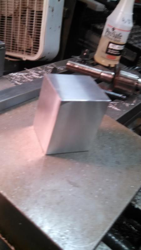
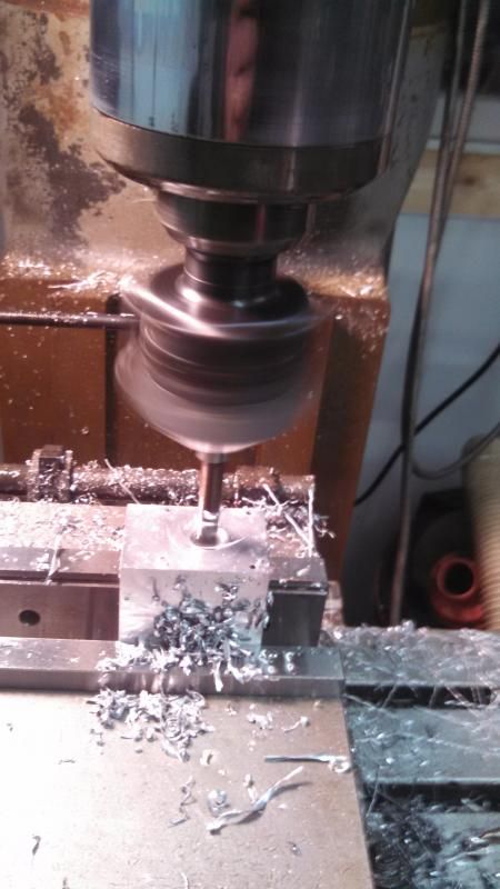
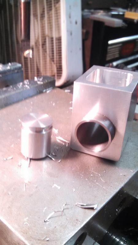
Got in some more shop time this evening. Worked on the water hopper. Started by turning a piece from my aluminum pile into a nice square/smooth blank as a starting point.


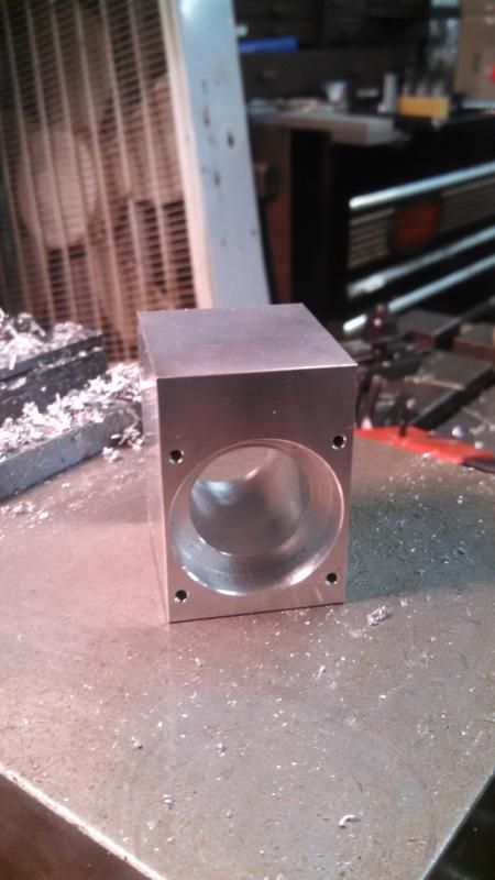
Started with the two stepped bores for the cylinder and the tapped mounting holes.


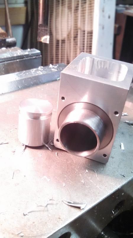
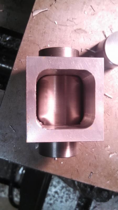
After that I hogged out the inside and after a few tweaks everything fit right in.


Although there is about 1/16" of radial clearance around the cylinder I'm concerned about trapping water underneath it after seeing it in place. I'm considering machining a relief in the middle to permit water to move more easily between the top and bottom of the hopper?

Also, you can see the piston blank in these photos. I machined it on the lathe in between passes of the fly-cutter when making the hopper blank. It's just the right OD and is an excellent fit. I also put the o-ring on for a trial and I'm a little concerned. It seems too tight to me. The o-ring is currently sized for ~10% squeeze, the same as some other members' engines. I can get the piston/o-ring installed and can move it, but it is very snug. I'll hope it breaks in a bit as a complete engine, or else when I lap the valves I may hit the cylinder with some lapping compound and see if I can make it even smoother (although it is quite smooth already).
 
1/16" radial clearance is all you need. There is no need for more radial clearance. I have at least 4 water cooled engines running with that radial clearance. As far as the o-ring squeeze goes--I use Viton o-rings (only one per piston). They measure 0.070" in cross section. I make the groove in my piston .057" deep, which is 81% of the ring cross section and that is about perfect on a 3/4" to 1" bore cylinder. I only use one ring per piston, as one is all you need to get a good seal, and two create too much drag.----Brian
 
Brian, it was on an earlier post of yours that I based my grooves. Same dimensions, .057" deep by .096" wide groove, just one. I'm hoping that when I get it on the engine with the connecting rod, which has much better leverage than my finger, that it won't feel so stiff. Thanks for the confirmation on the water jacket clearance.
 
As a general rule, the nominal thickness of an AS568 or ISO 3601 (standard) oring is not the actual size of the oring.

A 0-series oring is nominally considered 1/16" thick. Actually most of them (004 and above) are .070" The 1/16" thickness is the depth of the oring groove for about a 10% oring compression which is often a good guide for dynamic (sliding) seals.

So you have the following:

0 series - 1/16" nominal - .070 actual
1 series - 3/32" nominal - .103 actual
2 series - 1/8" nominal - .138 actual
3 series - 3/16" nominal - .210 actual

I design oring grooves all the time at my profession. For reasons not important here, I have to violate the published groove dimensions very often. Orings are very forgiving.

Also, the width of the groove isn't super critical. You can go too narrow when there is no room for the ring to squeeze into. You can go too wide (especially for dynamic seals) and the seal will roll in the groove. But as long as you stay about 150% wider than the oring, you're usually in good shape.


...Ved.
 
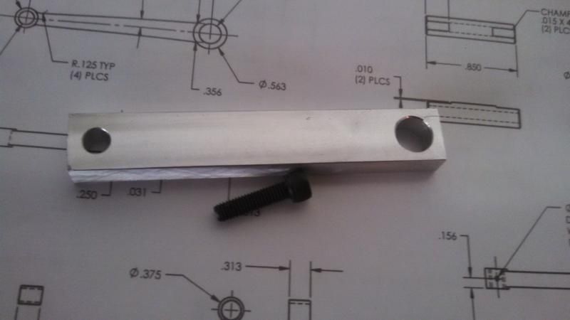
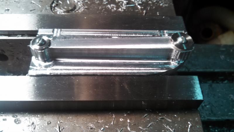
Still working away on the Webster. I've done a few easier parts that I didn't take pictures of (like the frame sides) but the tricky part I tackled today was the connecting rod. Started by making a blank and boring the two holes.


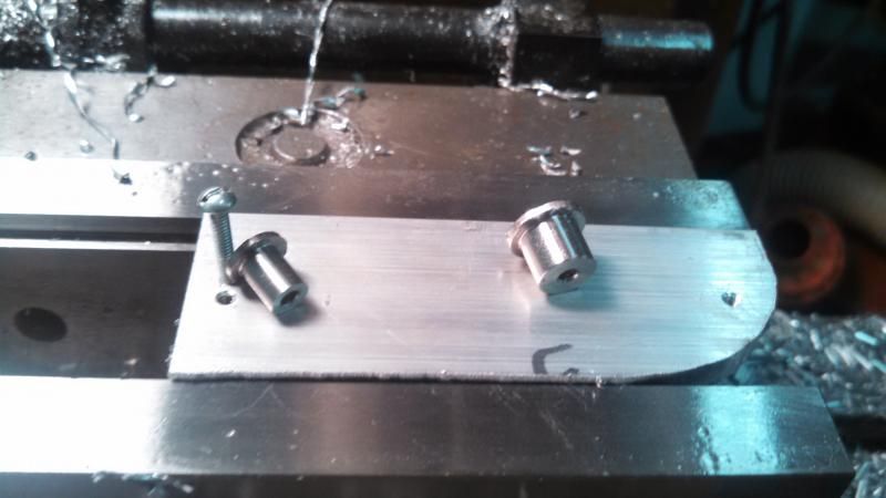
I then took a scrap of aluminum and tapped holes for the conn-rod in two different orientations. I also turned a pair of stainless bushings to bolt it down with.


A little roughing and it almost looks like a rod.


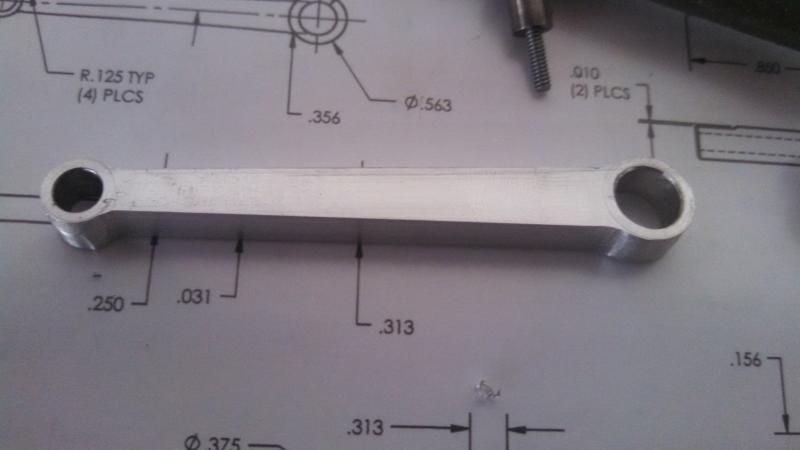
And the finished part.


I'm a bit surprised at how thin it looks around the main bushing end, but I suppose there are quite a few of these running and no one else has broken a rod? If I get time I may try for one a bit thicker than the plans call for just for peace of mind...
 
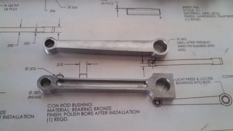
Decided I definitely wasn't happy with the connecting rod so I took a crack at a redesign. I left off the taper and went with my take on an "H-beam" rod:


Much happier with both the appearance, and the strength. Now I can move on :)
 
That is a nice robust looking con rod. However, it is dramatic overkill for the Webster, and all the additional weight around the big end will do is throw the engine out of balance.---Brian
 
Hi Leatherman
The connecting rod I made for my Webster, with the screws is probably around the same weight as yours and has a HUGE split bearing in the big end (don’t know why I made it so big scratch.gif). This is a lot of mass to be tossing around if the engine is running at any speed.

Big End Bearing.jpg
 
  • Like
Reactions: gus
To compensate I made up some bolt on counter weights. These are simple to make so you can adjust the size/weight as needed. If you look on the internet you can find the formula for calculating the weight needed. It’s something like half the con rod + piston + wrist pin – ½ your dogs age *2. The engine runs fairly smoothly and I don’t have to threaten it with a nail gun to keep it from going walkabout.

Counter Weights 01.jpg


Counter Weights.jpg
 
.. I left it .001" undersize so I could hone it.
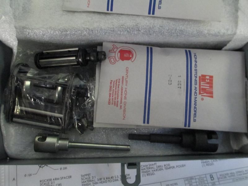
.. I picked up a set of hones for .75"-2" from an estate sale (the guy was a model engine builder).
.. I did learn that I shouldn't leave the bore a full .001" to allow for honing. It only took about .0002" to smooth it out

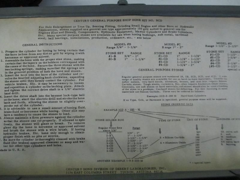
I'm interested in that hone, can you tell me anything more about it? Is it a commercial set or did you mean the previous owner made it? What kind of stones does it require & what grit did you use? Assume you motored in the lathe or a drill with oil etc? About how much time before you achieved finish? Did you measure any resultant diameter change (meaning taper)?
 
12L14 is notorious for rusting. Really bad rusting. I think you have chosen the wrong material for a hopper cooled cylinder.

Brian, I've heard this too. Having said that, what are the options for 'water boiler engine' liners? I cant imagine CI would be much better, it would require stainless steel type ingredients, no? What were the FS engines using or how did they mitigate?
 
I don't profess to be an expert on boiler materials. I don't even know that much about 12L14.---It's just that I have seen numerous posts about how badly 12L14 rusts from exposure to humidity in the air inside a house or shop. I know that cast iron will rust, but it is popular for cylinders because of the graphite which makes up part of its metalurgical properties. I made my first hit and miss engine (the Kerzel) with a 316 stainless steel cylinder and an aluminum piston, because I didn't want to look down the top of the water reservoir and see a rusty cylinder. I used a Viton o-ring on the piston, and never had a problem with differential expansion between the piston and cylinder. Later I made a Philip Duclos hit and miss engine with a cast iron cylinder, and although eventually it did rust on the exterior it never rusted badly enough to cause a problem. (I drain the water out of my engines when not using them). I really don't know how good a cylinder 12L14 will make in terms of wear properties, but if it rusts as badly as I have been warned about simply from humidity in the air, then it can't be good to have it immersed in water.---Brian
 
  • Like
Reactions: gus
To compensate I made up some bolt on counter weights. These are simple to make so you can adjust the size/weight as needed. If you look on the internet you can find the formula for calculating the weight needed. It’s something like half the con rod + piston + wrist pin – ½ your dogs age *2. The engine runs fairly smoothly and I don’t have to threaten it with a nail gun to keep it from going walkabout.

Hi Bob,

Planning to have a DIY MiniMagneto driven by the Webster I made 2012. Will
have the flywheel counter balance using your formula. Its true the Webster vibration nearly caused my Makita BandSaw to crash from work bench to the floor.
Happy New Year.
 
I kind of dropped off the radar for the last couple of weeks. I got the engine about half mocked-up to be able to "give" it to my Dad on Christmas and then took it back to keep working. Since then I've had to catch up on house work, and the FIRST robotics team I've been mentoring has had several competitions and required a lot of time and parts.

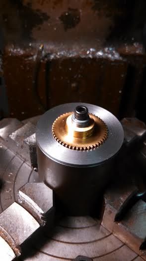
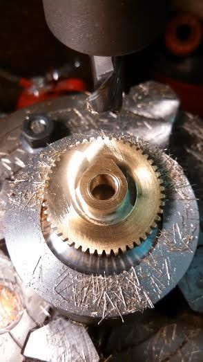
Starting back in I machined the cam. The plans called for this to be made from steel and pressed onto the gear. I'm building the engine to run a ball bearing roller on the rocker, so the cam doesn't need to be hardened. I decided to try machining it right onto the boss on the gear. First I made a mandrel to hold the gear, then I machined it on the rotary table:


Somewhere I messed up my calculations and the finished cam has less duration than called for (.175" instead of .250"). I'll give it a shot anyway, and if need be I'll machine it off later and make a cam separately like the plans called for.
 
A little random knowledge about cam shapes and cam followers.--The Webster engine, in it's original form, did not have a roller on the rocker arm. This means that the cam should have had a radius on the cam flanks (instead of flat sides). With flat sides on the cam, every time it revolves the flat side of the cam will "slap" the rocker arm. If the cam had a radiused flank, it would raise the rocker arm in a more gradual motion and not "slap" it. Cams with flat sides do work well with a "roller follower" because the roller can more closely follow the contour of the cam without getting "slapped" each time the cam revolves.--So, your plan for a bearing as a cam follower is a good one.--However--This bit of arcane science doesn't seem to matter to much with the Webster, because it is a low powered, low revving engine, and seems to work just fine as designed. I am sure that on higher powered, faster revving engines this effect of flat flanked cams as opposed to radius flanked cams makes a large difference to engine performance. I don't think the Webster really cares too much, and will perform well either way.
 
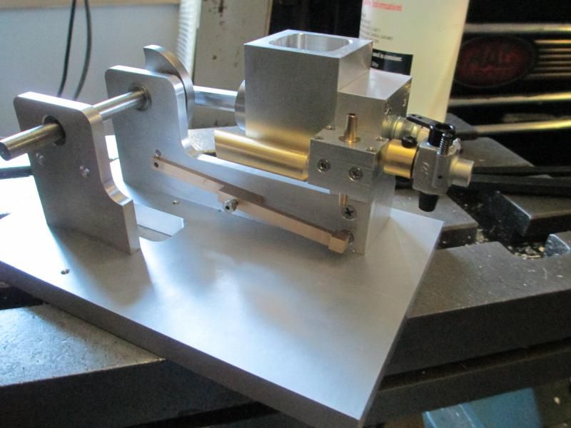
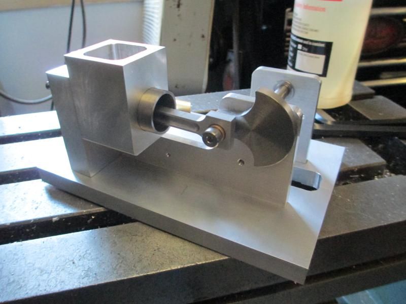
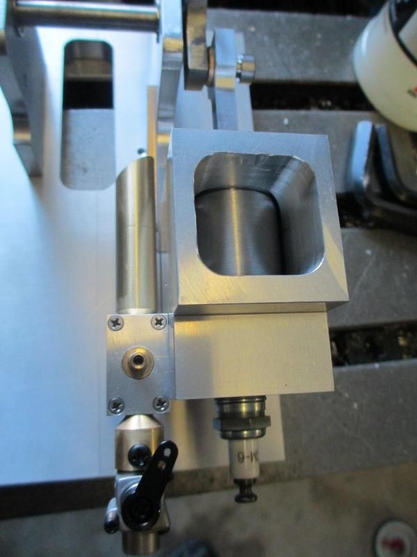
To address a few earlier points, here are pictures of the "mock-up" which is as far as I got in time for Christmas:


I did attempt a "balanced" crank to offset the rod weight and to attempt the keep the engine from walking around too much when running. Got the carb adapter done and installed for an OS #10G model engine carb. Still needs the cam finished, the top of the water hopper, a lot of miscellaneous spacers/bushings/hardware, the points I got didn't include the isolator that the wires mount to so I have to make something for that, and a fuel tank.
 
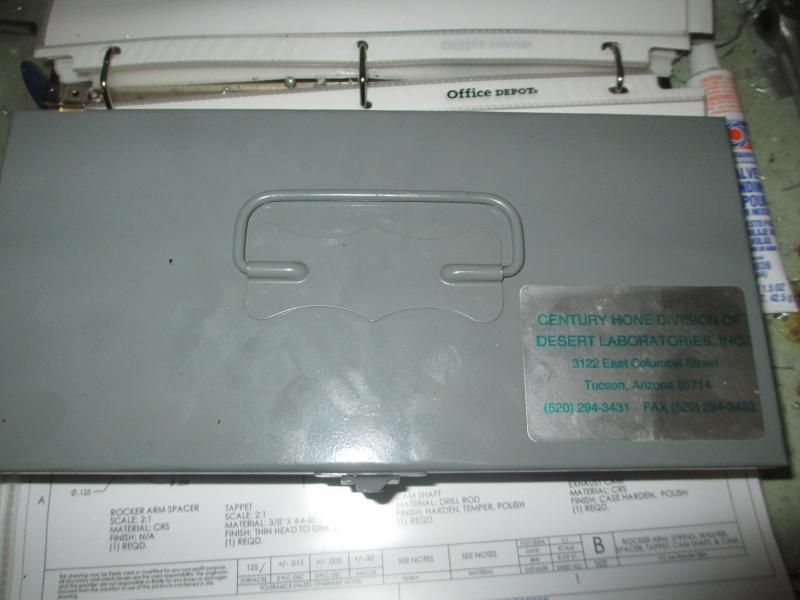
petertha, the hone was a commercial kit. It came with 3 sizes of hones, each of which takes 2 sizes of stones, along with the various drives and such. No idea if they're still in business, but there's a phone number on the lid. Here are some pictures:


A little random knowledge about cam shapes and cam followers.--The Webster engine, in it's original form, did not have a roller on the rocker arm. This means that the cam should have had a radius on the cam flanks (instead of flat sides). With flat sides on the cam, every time it revolves the flat side of the cam will "slap" the rocker arm. If the cam had a radiused flank, it would raise the rocker arm in a more gradual motion and not "slap" it. Cams with flat sides do work well with a "roller follower" because the roller can more closely follow the contour of the cam without getting "slapped" each time the cam revolves.--So, your plan for a bearing as a cam follower is a good one.--However--This bit of arcane science doesn't seem to matter to much with the Webster, because it is a low powered, low revving engine, and seems to work just fine as designed. I am sure that on higher powered, faster revving engines this effect of flat flanked cams as opposed to radius flanked cams makes a large difference to engine performance. I don't think the Webster really cares too much, and will perform well either way.

Brian
How would you reac if every single time you would post something
you would have a NEGATIVE opinion on what you did:hDe:
Let him enjoy his build, I'm 100% sure if he needs help he will ask:fan:
JLeatherman go for it I'm watching, and enjoying:)
 
Back
Top