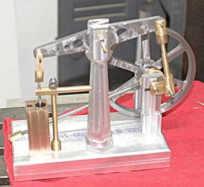
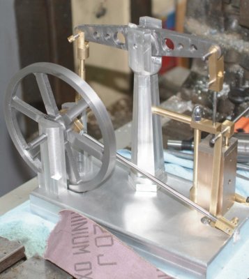
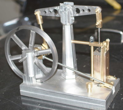
My build of Brian's double scale beam engine

Home Model Engine Machinist Forum

Help Support Home Model Engine Machinist Forum:

This site may earn a commission from merchant affiliate links, including eBay, Amazon, and others.
I had some shop time this afternoon as it's raining lightly outside.

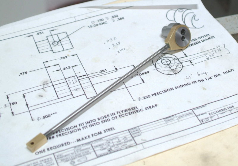
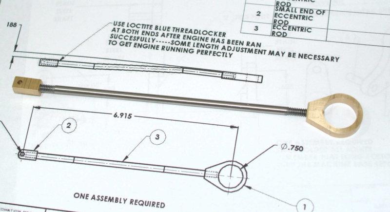
Further exploring threading on the lathe, I cut ~7" of 3/16 drill rod to make the eccentric rod, chucked it, and cut partial 24 tpi threads in each end. I then finished the threads with a 10-24 die, using the partial threads to start the die straight on the rod. The rod is longer than shown in the plan, but I will be able to cut to fit as there are extra threads on each end.
large.jpg


I also did the same to make 10-24 threads on the top end of the piston guide support.

Unfortunately I had an "oops" as I began to drill the base. My "bling" column's base is wider than spec, and I had made the base wider as well. Unfortunately I failed to take that into consideration and drilled the holes too close to the edge. So I will have to make a new base tomorrow night at school. :mad:
 
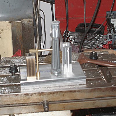
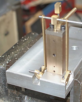
Had a few minutes to "trial fit" the parts that attach to the base:

medium.jpg


Everything is fastened to the base from underneath with screws, as opposed to from the side as in Elmer's design. Since the bearing supports are two pieces I will need to deviate from the plan in terms of where to mount them. Basically the center of the bearing hole needs to be vertically aligned with the hole at the end of the beam when the beam is level.

The valve levers will be in pockets milled into the base rather than to the sides, as I am keeping the base rectangular for "esthetic" purposes.
 
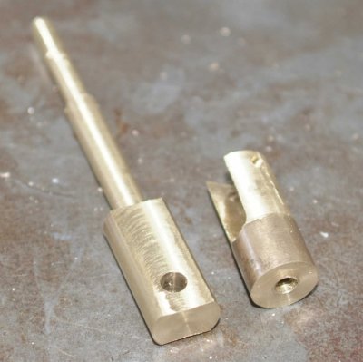
Had a session in the shop this afternoon making the connecting rod parts.

medium.jpg


I turned the end and rod from a single piece of .5" round brass bar. I cut the partial 10-24 threads on the lathe, then used a die to finish them. Then I clamped the rod in a 5c collet with the square collet block, mounted in the milling vise, and milled the flats on opposite sides of the end. Then drilled the hole for the crankshft.

Not having any square brass bar for the clevis I again used the .5" round rod. Cut a length with the hacksaw, faced both ends on the lathe, and then clamped in the collet block on the mill. I used a 1/4" end mill to create the slot, and then drilled the holes for connecting to the beam.

Back to the lathe to drill and tap the through hole for mounting to the connecting rod.

I believe that I have only the top bit of the valve to make, and then it's a matter of putting it all together.

I got my Enco delivery today with boxes of 5-40 pocket head machine screws and 5-40 set screws, so I will have a number of holes yet to drill and/or tap.
 
I had a couple of hours last night to work in the shop. The first task was to remake the piston rod end so that the connection to the rod would be a 5-40 thread to match the rod. Then it was on to fitting the valve and piston in the bores of the cylinder.

The piston already fit fairly well, so I mainly had to clean up internal burrs in the bore from the inlet holes. A little touchup from a needle file and some spindle oil lets the piston slide up and down pretty well. I think that when it's all together running it with a drill, as Brian did, will polish the bore pretty well.

The valves were a much tighter fit, and as well there were burrs from the holes. I ran the 1/4" reamer down the bore once more to clean things up. Then I "polished" the valve rounds with some fine emery cloth and Scotchbrite until they would enter the bore. The fit is still sticky, but I'm going to try the toothpaste lapping technique next.

I'm wondering what is the best way to plug the air holes on the outside of the cylinder. I don't want to do that right away as leaving them open will make the "tuning" easier as then I can see the position of the valves during operation. If I solder the holes shut then I will likely need to ream off the excess in the bore as well as mill the outside of the cylinder block.

I also need to figure out how to construct and attach the air feed tube. I'm thinking that I can thread the hole. If I screw in the feed tube after the valves are in place it won't hurt if if extends a little bit into the valve bore.
 
kvom---When I built mine I made little brass plugs and soldered them into the outside of the cylinder to plug those holes, and I soldered the air inlet in place. When I went to test run the machine, I just played with the valve timing untill I got lucky and it ran.---Brian
 
I did a bit more lapping of the valve bore this afternoon. It's not quite there but getting smoother. Most of the interference seems to be at the bottom.

I then decided to put together my 2-piece eccentric. I built it this way for two reasons:

1) To mill a retaining flange to keep the eccentric strap from "walking", and

2) I didn't have a lot of confidence in turning a 1-piece on the 4-jaw.

So I had two pieces, each with a 1/4' reamed hole. I needed to be able to screw the two together with a 5-40x1/2" capscrew. In order ensure that the holes for the screw would like up with the crankshaft passing through the assembly, I decided to baptise the 1-ton Palmgren arbor press I recently bought from Enco.

I used the press to push a short length of 1/4" drill rod through the reamed holes giving a nice press fit. I was then able to secure this assembly in the mill vise. Having calculated the offset of the screw hole I drilled through the outer piece with a #28 drill. This established the proper hole for tapping 5-40 threads in the inner piece. I then separated the two pieces, tapped the inner hole, and enlarged the hole on the outer to match the major diameter of the screw, and finally drilled a countersink for the head of the screw.

large.jpg
 
It's a lot easier to make progress when your shop is 30' away rather than 30 miles! ;D

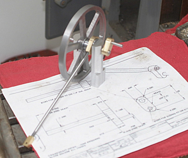
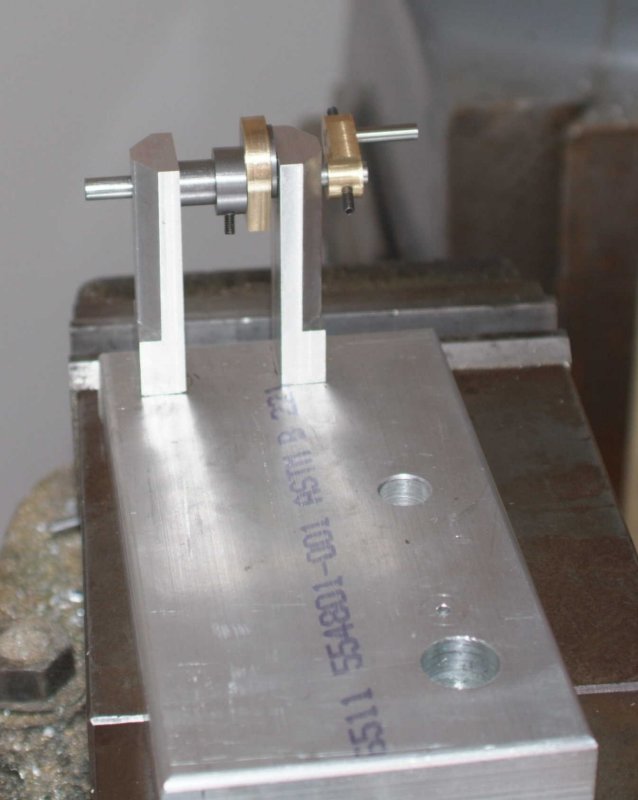
This morning I put together the crankshaft. The press fit is fairly tight and would probably hold when running, but I drilled and tapped holes for setscrews. Then I did a trial fit of the various pieces that connect to the crank:

large.jpg


The shaft spins very freely in the Al bearing supports. I'm not sure how much space to leave between them, but probably .01 on each side will be enough.

The eccentric is loose in the flywheel bore. While locktight would work I think it might be possible to drill a hole at an angle for a setscrew. I don't have a way to hold the flywheel to drill that hole, so I'll try to do that at school: clamp the wheel in a grinding vise and then clamp that in the mill vise at an angle that gets clearance. That way I can take everything apart for polishing once it's a runner.
 
Kvom,

Coming together very well

Best Regards
Bob
 
I put some more pieces together this afternoon.

When I made the beam some months ago I drilled the end hole 1/4" instead of 1/8", so I needed to make some brass bushings on the lathe in order to attach the connecting rod clevis and the piston rod strap. This took a bit of time and filing.

Then I needed to get a smooth slip fit between the connecting rod and the support. Used emery cloth, scotchbrite, anbd finally toothpaste. Seems to be pretty good now, but we'll see when it runs.

I put the pieces roughly together:

medium.jpg


Although the bearing legs aren't attached yet I could tell by trying to turn the crankshaft that something needs adjusting. Some calculations looking at the plan showed that I have made the bearing .313" too high. Tomorrow I'll mill off the extra and drill/tap the mounting holes.

Next todo items after that is ensuring a fit between the piston rod and the cylinder head, at which point I should be able to adjust the lengths of the connecting rod and piston rod so as to get the correct travel range for the piston. I also probably need to make some brash bushings for the beam, as there is a bit too much space between it and the sides of the column.

Saving the valve levers and adjustments for later.
 
This afternoon I reduced the height of the bearing legs and drilled and tapped mounting holes in them. Then I drilled through holes in the base to correspond and countersunk them on the bottom. I could then attach the legs to the base with 6-32 screws.

large.jpg


It's necessary to tighten the screws gradually to maintain the precise alignment of the crankshaft and the bearing holes, but once in place the cramkshaft turns very freely.

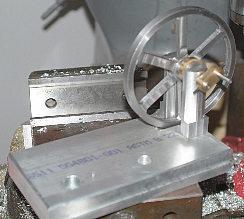
Since the legs are shorter than before, the flywheel would now touch the base, so it is necessary to mill a 0.2" deep relief pocket in the base. After a few trials we have a decent fit:

large.jpg


Before I put the pieces back together I think it's time to flycut the top of the base. I also need to drill the setscrew in the flywheel hub.

The piston/piston rod/cylinder head/rod support aggregation is still a bit stiff when worked by hand. Once i get the rest hooked up again I should be able to exercise the piston by turning the crankshaft with a motor, less work than manual for sure.
 
Now that's a very nice looking engine you got happening there Kvom Thm:

You've certainly got a good eye ;)


Once i get the rest hooked up again I should be able to exercise the piston by turning the crankshaft with a motor, less work than manual for sure.

Now I can't remember the thread where I read this but it is as I recall a bad idea to run an engine in from the crank side, Un-natural wear on the parts.... I remember reading that it is just better to oil everything up and run it on air to get the correct wear into the places it needs to be.


Hope this makes sense.... It figures right to me.


I'm looking forward to seeing this finished ;D


Ralph.
 
Coming together nicely, KVOM. Really looking great!

Chuck
 
had a couple of hours in the shop this morning. My first thing to try was cutting down 5-40 set screws from 3/8" to around 3/16" in length. I clamped them in a 1/8" 5C collet in a hex collet block, then put the block on the lathe held with the 6-jaw chuck. It didn't work too well with a parting tool, but the hacksaw does work.

I also "broke in" my new Enco 5-40 die and diestock on some 1/8" drill rod. I'm using the lathe to cut the threads 80% and the die to finish. The threaded pieces will be used to hold the parts together. I bought some 5-40 hex nuts, but I don't think they look very good given the first piece. I think I may end up making some brass nuts from the 3/16" square stock I have. In the meantime the zinc nuts will do to get it running.

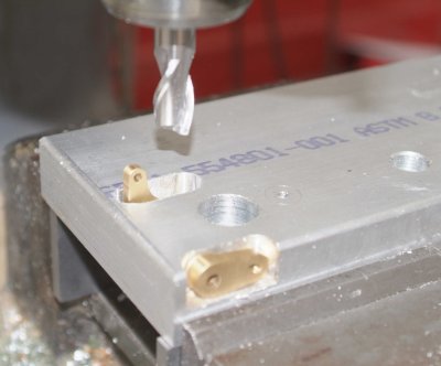
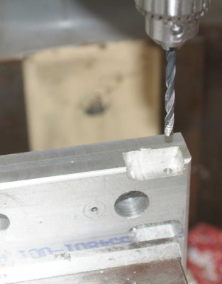
The next job was to mill the pockets in the base for the valve levers:

medium.jpg


The, drilled the through hole for the rod connecting the levers:

medium.jpg


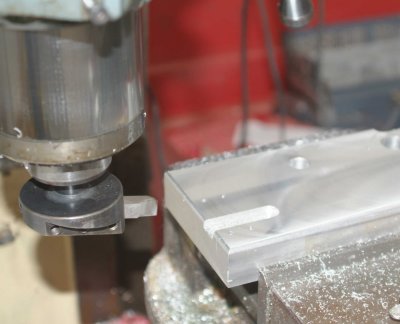
Finally, flycut the top of the base:

medium.jpg
 
Kvom,

I don't know when the hex nut came into being but I would say there is a fair chance that the nuts and bolts used on beam engines were square headed.

Best Regards
Bob
 
FWIW, My usual small-screw-shortening method is to screw them into a pre-tapped piece of scrap, then press the end sticking out into a bench grinder. Zips 'em down in no time, then unscrew them to repair the thread on the end.

Long ago Bogstandard had a great post on making and using studs for better realism on model steam engines that you might want to check out if you're into that.
 
I think that grinding is the right way to shorten screws a little. While I have been waiting to get the final inspection on the garage I haven't had access to my bench grinder.

I'm going to make a couple of the brass squares nuts tomorrow just to see how they look.
 
Because of weekend family commitments, I got to spend only a couple of hours in the shop. Main accomplisment was to drill and tap holes for setscrews for the valve levers and the beam. Got a trial fit on the levers, and started to try to adjust the length of the valve. I also cut the rod to support the center of the beam in the bearing legs.

I think a few more hours will permit me to assemble the entire engine altogether and try to operate it manually and adjust the valve linkage/eccentric rod.

I will still need to plug the two holes and fabricate an air feed tube. I did purchase a regulator valve and gauge to allow me to control the air pressure to the engine.
 
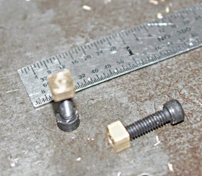
Got a couple more hours to play this afternoon. I did make some square brass nuts out of 3/16" square rod drilled and tapped 5-40. I used the square 5C collet I bought for making nuts for TB3, clamped the rod in the collet and hex collet block, and chucked the block in the lathe. After drilling and tapping I parted off 4 nuts. The nuts are .2" thick, and unfortunately the single parting tool I own is .11" thick, so I waste almost as much brass in parting as for the part itself.

medium.jpg
I need to make another 6 I think.

I then assembled the flywheel/crankshaft/bearings with the column/beam and the cylinder piston. The cylinder has a pretty good sliding fit now and the mechanism is easy to operate by turning the crank. I did get quick a bit of rubbing between the crank lever and the connecting rod end. I slipped a steel washer between them, and this seemed to remedy the situation. I also needed to mill the crank thinner than the plan to get a smooth operation and for the connecting rod to line up properly. I discovered that I have some binding of the mechanism when I screw the column down tightly to the base. I think it's because the bearing holes for the beam shaft were not drilled perfectly. If I leave the column a bit loose then everything turns OK.

Then I did a trial fit of the valve levers, straps, and the valve:

medium.jpg
Then finally a trial assembly of the who shebang:

medium.jpg

The eccentric rod is quite a bit too long. I need to determine the proper positions of the valve during the rotation in order to set it properly. It's threaded on both ends to allow fairly easy adjustments. I believe the brass head portion of the valve needs to be shortened or raised, since when it touches the cylinder head the upper hole is still blocked. The rod connecting it to the valve body is threaded, so I hopefully can adjust it according to Elmer's drawing.

Still a fair amount of work to do, but at least the end is in sight.
 
I got it put together with the eccentric and valves adjusted so that it "ought" to work with some air applied. I now need to solder in the feed tube (sitting on the base) and plug the two valve holes with solder. I bought some solder today and have a mapp gas torch, but I will practice a bit on scrap first.

Although it works OK when cranked by hand, I will need some additional fixups when I take it apart for bling. The eccentric clevis tends to walk off the lever rod, so I want to thread the end of the rod and make a retaining bolt. I also need to fix the pivot point of the column, where I drilled the holes slightly off, so that there is binding when the column is crewed down tight. I think I will drill new larger holes in the correct orientation and put brass bushings in with loctite.

medium.jpg
 

Latest posts

Back
Top