
You are using an out of date browser. It may not display this or other websites correctly.
You should upgrade or use an alternative browser.
You should upgrade or use an alternative browser.
Mirror Finish Fly Cutter
- Thread starter celsoari
- Start date


Help Support Home Model Engine Machinist Forum:
This site may earn a commission from merchant affiliate
links, including eBay, Amazon, and others.
BaronJ
Grumpy Old Git.
Hi Guys,
I posted pictures of mine ten years ago !
I posted pictures of mine ten years ago !
Nice built.
I was able to turn on english captions, and so that worked out.
Makes an impressive finish.
I need to build one of these.
.
I was able to turn on english captions, and so that worked out.
Makes an impressive finish.
I need to build one of these.
.
BaronJ
Grumpy Old Git.
Hi GreenTwin,
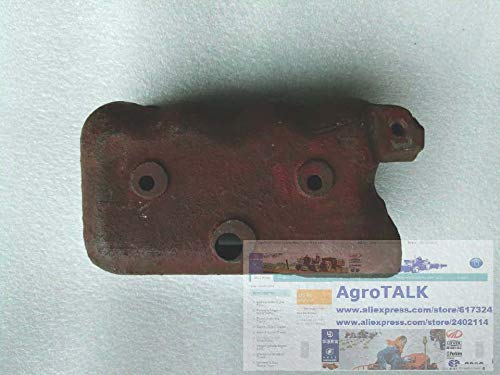
Here are pictures of mine. I have drawings kicking about somewhere as well !


No milling ! Just thee holes. One for a 20 mm shaft, one for a 6 mm square tool bit and a M6 threaded hole for a grub screw.
The disc is made from the off cut of a 100 mm steel bar, 20 mm thick with a pressed in steel shaft.
The surface finish is what ever you want depending upon surface speed and material being machined.
Here are pictures of mine. I have drawings kicking about somewhere as well !
No milling ! Just thee holes. One for a 20 mm shaft, one for a 6 mm square tool bit and a M6 threaded hole for a grub screw.
The disc is made from the off cut of a 100 mm steel bar, 20 mm thick with a pressed in steel shaft.
The surface finish is what ever you want depending upon surface speed and material being machined.
Fly Cutter that was built to give a mirror finish
Greetings from Brazil
Celso Ari
Very nice, thanks for sharing!
John W
I might make one too....I guess it would cut ok, being a full circumference tool head, balanced, and wouldn't bounce on impact of intermittent cutting....Nice built.
I was able to turn on english captions, and so that worked out.
Makes an impressive finish.
I need to build one of these.
.


$40.02
$49.99
Becker CAD 12 3D - professional CAD software for 2D + 3D design and modelling - for 3 PCs - 100% compatible with AutoCAD
momox Shop


$156.90 ($1.40 / oz)
Replacement Combustion Chamber Kit, Burnham V8 and V8H, 1-6 Sec, 108136-01, 1129
Lynn Manufacturing


$649.00
$699.00
FoxAlien Masuter Pro CNC Router Machine, Upgraded 3-Axis Engraving All-Metal Milling Machine for Wood Acrylic MDF Nylon Carving Cutting
FoxAlien Official


$94.99
$109.99
AHS Woodmaster 4400 Maintenance Kit for Outdoor Wood Boiler Treatment
Alternative Heating & Supplies

![MeshMagic 3D Free 3D Modeling Software [Download]](https://m.media-amazon.com/images/I/B1U+p8ewjGS._SL500_.png)


$426.53
DM14 Engine Build Kit, Metal Engine Build Model Great Metal Material for Engineer for Factory
Easoger Official


$99.99
AHS Outdoor Wood Boiler Yearly Maintenance Kit with Water Treatment - ProTech 300 & Test Kit
Alternative Heating & Supplies


$29.95
Competition Engine Building: Advanced Engine Design and Assembly Techniques (Pro Series)
Amazon.com Services LLC


$109.99
AmTech300 - Boiler Treatment Professional Strength (Rust Inhibitor For Outdoor Wood Boilers)
Alternative Heating & Supplies

$39.99
$49.99
Sunnytech Low Temperature Stirling Engine Motor Steam Heat Education Model Toy Kit For mechanical skills (LT001)
stirlingtechonline


$45.99
Sunnytech Mini Hot Air Stirling Engine Motor Model Educational Toy Kits Electricity HA001
stirlingtechonline

$188.98
TM NEXDYNAMI RE41157 Water Pump Compatible With/Replacement For/John Deere 6200 7400 6300 6600 6500 6400 7220 7600 7200 RE41157
VIVID MARKET CORPORATION


Celsoari, Baron,
Excellent! A good stiff holder for the tool.
I think the correct tooling, workpiece material, speed and feed all play a part as well. But this shows you know what you are doing. What shaft speed, depth of cut, feed-rate and workpiece material were you showing? A close-up of the tool shape would help too? Excellent stuff!
One industrial job, in a workshop I managed, was making electrical joint faces (For LARGE busbars) using a similar tooling to face aluminium bars 6 inches wide in a single pass. The machine was a woodworking tool running 6000rpm! A 1mm cut cleaned-up the raw surface in a single pass and using a sharp pointed tool gave the surface finish - not mirror-like - of grooves and peaks so when the joint was bolted-up the intersecting aluminium peaks deformed each other to make a very low resistance (metal to metal) good joint.
The swarf flew from that machine!
That job had a fly-cutter holder very similar to yours.
I am sure a radiused tool would have given a mirror finish on that machine too.
Thanks,
K2
BaronJ
Grumpy Old Git.
Hi Ken,Celsoari, Baron,
Excellent! A good stiff holder for the tool.
I think the correct tooling, workpiece material, speed and feed all play a part as well. But this shows you know what you are doing. What shaft speed, depth of cut, feed-rate and workpiece material were you showing? A close-up of the tool shape would help too? Excellent stuff!
One industrial job, in a workshop I managed, was making electrical joint faces (For LARGE busbars) using a similar tooling to face aluminium bars 6 inches wide in a single pass. The machine was a woodworking tool running 6000rpm! A 1mm cut cleaned-up the raw surface in a single pass and using a sharp pointed tool gave the surface finish - not mirror-like - of grooves and peaks so when the joint was bolted-up the intersecting aluminium peaks deformed each other to make a very low resistance (metal to metal) good joint.
The swarf flew from that machine!
That job had a fly-cutter holder very similar to yours.
I am sure a radiused tool would have given a mirror finish on that machine too.
Thanks,
K2
I've been using this style fly cutter for a lot of years now ! I know that a lot of people have built one. I know of one that has two cutters in it 180 degrees apart but on slightly different radii.
I've, depending upon material used a 1 mm DOC without any problems. I've even used it to surface hardwood, using the drill press. The centrifugal effect of the heavy disc does make a difference to the surface finish compared to the conventional swinging arm type cutter.
Interesting your comment on low surface resistance joints. I did find that worn carbide tool bits tended to produce a burnished finish rather than a cut one on some steels. The tool shape also makes a large difference to the surface finish. I started by using the rounded shape that you see in the picture, but found that a shape more like a lathe tool was more effective.
THANKS Baron.
I agree with cutting using a lathe tool, as while used on lathes against a curve of the cylinder, the same cutting angles are a relationship between the tool and workpiece material, not any perticular machine. And for model work, on "smaller less-stiff machines than needed for industry, smaller cuts with a sharp tool are easier than heavier cuts where "less sharp" carbide inserts are intended.
K2
Must admit that my flycutters seldom get use dthese days. I've gone over to insert face mills as they can be feed at 5-6 times faster for the same given chip load as a single point flycutter and as there is usually at least one insert in the cut all the time the gears in the mill's head run a lot quieter.
Flycutter with HSS may want a feed rate of 25mm/min, insert facemill can go at 400mm/min as the carbide can also be run faster. Also not going to get instantly blunted by a hardspot in a casting
Flycutter with HSS may want a feed rate of 25mm/min, insert facemill can go at 400mm/min as the carbide can also be run faster. Also not going to get instantly blunted by a hardspot in a casting
Thanks Jason. Useful information.
K2
K2
In a shaper a tool bit ground to produce a shearing action rather than a cutting action leaves a really nice finish. You have to take light cuts and a step over that is smaller than the radius of the cutter so it is slow going. Easy enough to get it started and go do something else.
I wonder if a shearing bit would work in this tool?
I wonder if a shearing bit would work in this tool?
Do shapers run a fast cutting speed or slow?
K2
K2
I think most are adjustable for stroke length and speed as well as step over amount.
On mine anyway, there are different pulley speeds on the drive from the motor. Then as the stroke length changes, it effectively changes the tools speed as well. Like a lathe with fixed pulley speeds you try to find one that gives the best cutting speed at a particular diameter. In this case a stroke length/pulley combination that works for a particular setup.
The Scotch Yoke mechanism turns at the RPM from the input pulley. But the because of the geometry of the yoke long strokes move the slowest and short strokes are the fastest for any given pulley size. The other cool thing is that the back stroke is always faster than the cutting stroke.
The design of that thing was a "stroke of genius", pun intended.
Material type and cutter type all play into getting a good finish just as it does on the lathe.
My shaper manual shows how to make a shear tool and it should work in both the shaper and the lathe. That is why I was wondering if it would work in this fly cutter on the mill. My guess is that it would.
Since the cutter in this tool is vertical rather than angled, it would seem that the same cutter used on the shaper or the lathe would work just fine once you got the speeds and feeds dialed in. My experience with mild steel stock is that a HSS shear tool can only take .001 or .002 depth of cut. Definitely for finishing passes only.
I saw a video one time that was a good explanation of the shear tool. Don't remember for sure but I think it was Mr. Pete.
Thanks piper, a new one for me!
Good stuff!
Thanks for posting!
K2
Good stuff!
Thanks for posting!
K2
I think the nearest I have come to this in the past was the use of a round *Bull-nosed" tool for the final cut to get a better fining than the sharp point and slow feed. but that used a cutting action, not a shearing action as the video demonstrates.
K2
K2
It's better to buy them this way but to improve the facing finish of an end mill, grind a small radius on the corner.I think the nearest I have come to this in the past was the use of a round *Bull-nosed" tool for the final cut to get a better fining than the sharp point and slow feed. but that used a cutting action, not a shearing action as the video demonstrates.
K2
Thanks. That's another new one for me!
I'll try it! - I'm happy with lathe work, but there are many tricks and "specials" for milling that I never had the chance to learn. - Just another area of machining that keeps me glued to this site.
K2
I'll try it! - I'm happy with lathe work, but there are many tricks and "specials" for milling that I never had the chance to learn. - Just another area of machining that keeps me glued to this site.
K2
BaronJ
Grumpy Old Git.
Hi K2, Ken,
The same works on lathe tools !
The idea is that the cut is spread over a very small area, wide enough to remove the fine ridge when cutting with a sharp pointed tool.
The same works on lathe tools !
The idea is that the cut is spread over a very small area, wide enough to remove the fine ridge when cutting with a sharp pointed tool.