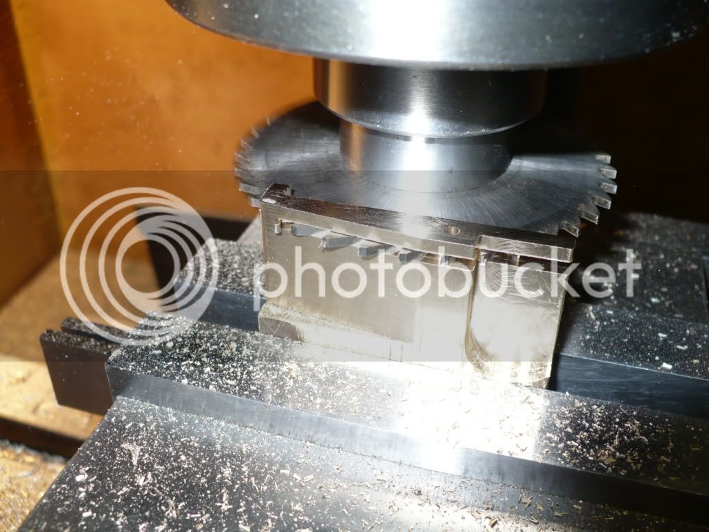
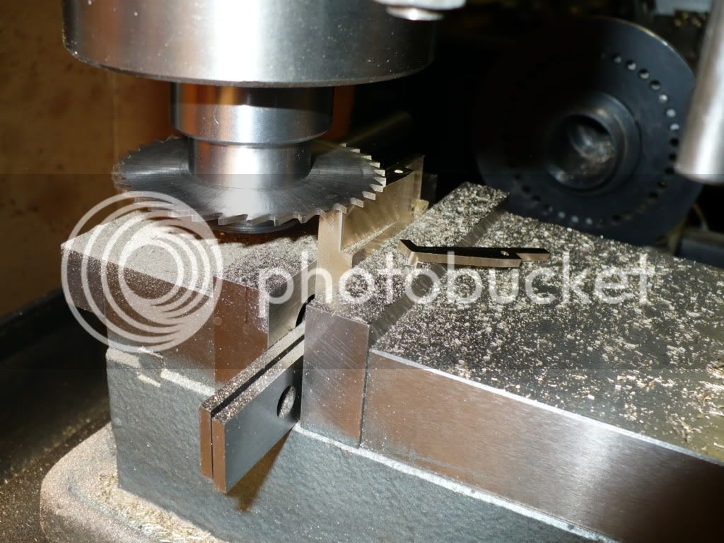
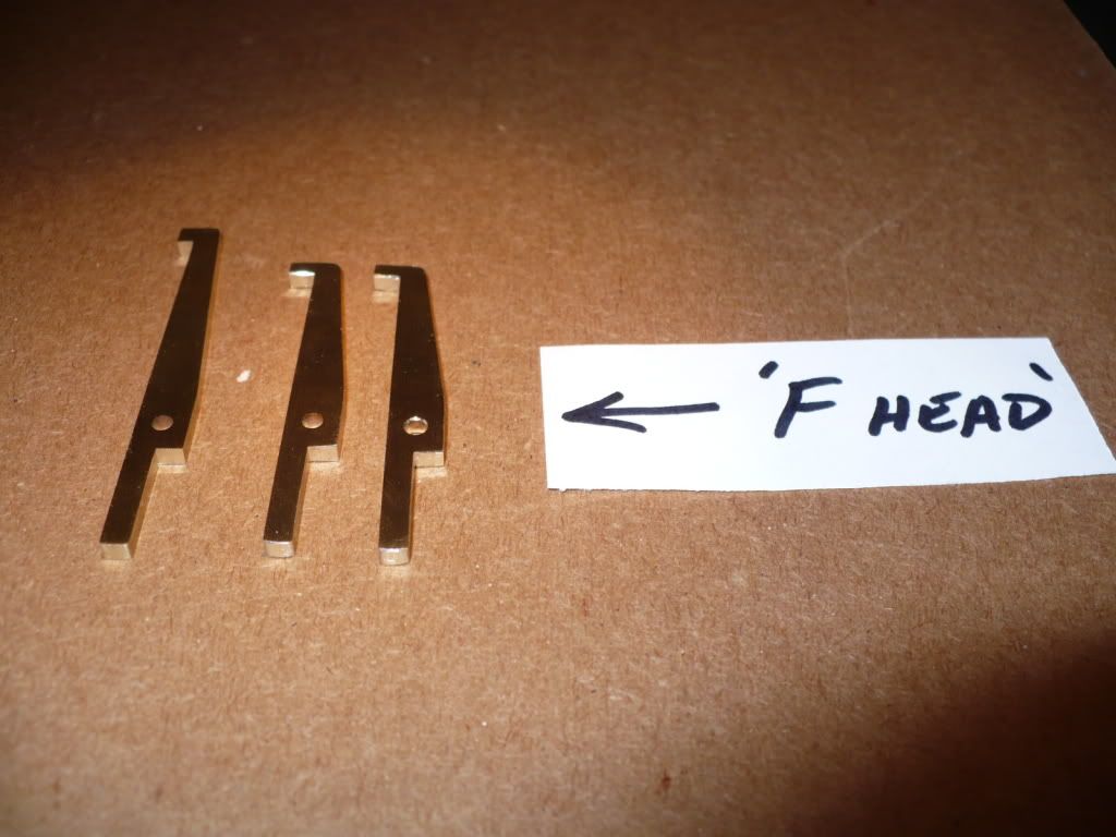
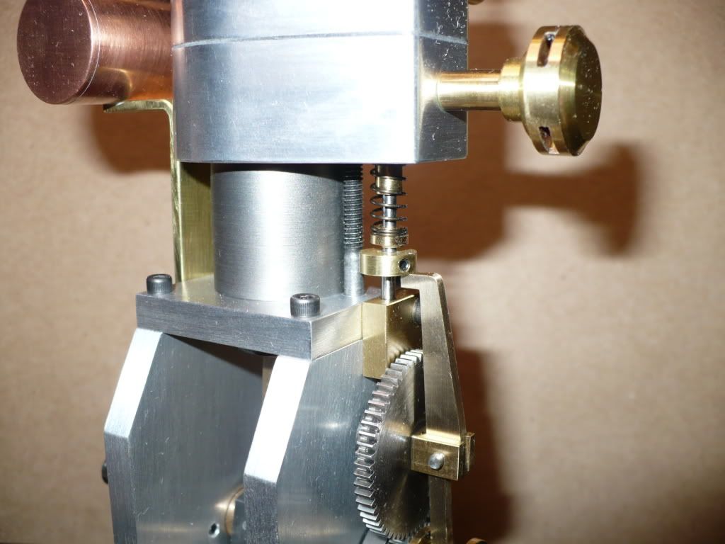
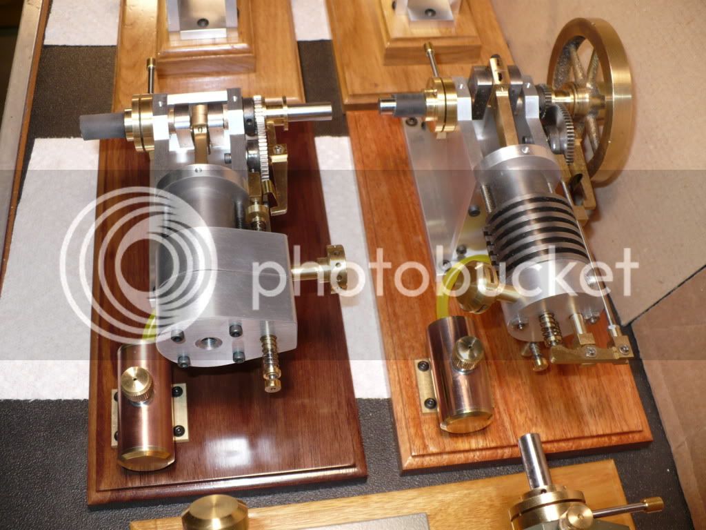
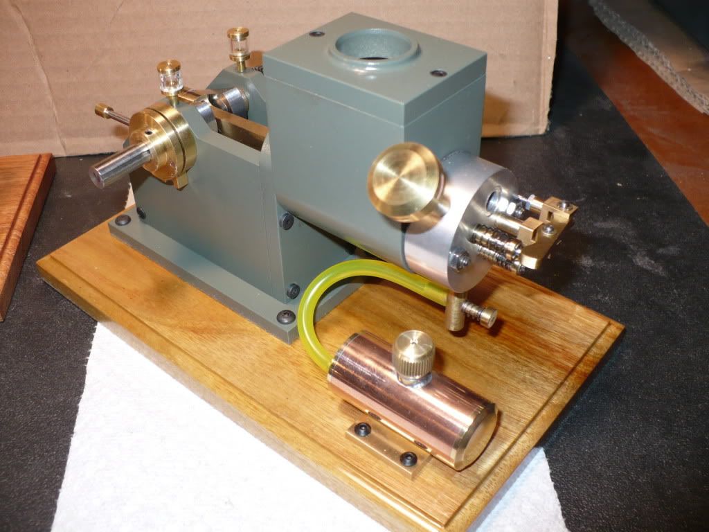
Hi Mike. Yes, I changed the side plates for a cosmetic preference. I lowered the area you mention along with the radius on the front plate. It was important to stay short (above) of the crank's center line, and the mounting hole for the cam gear.
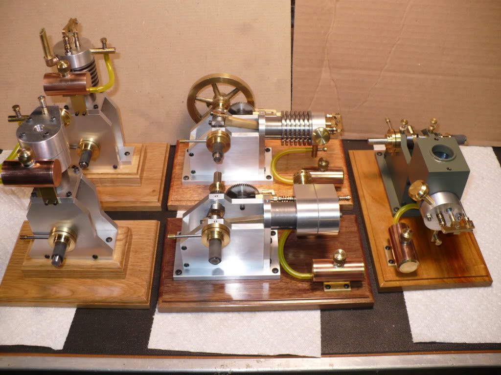
#314 I finished cleaning up the five fuel tanks and attached them to tier bases with 2- part epoxy (JB-Weld). Soldering them to their bases would have probably ended with a disastrous result.
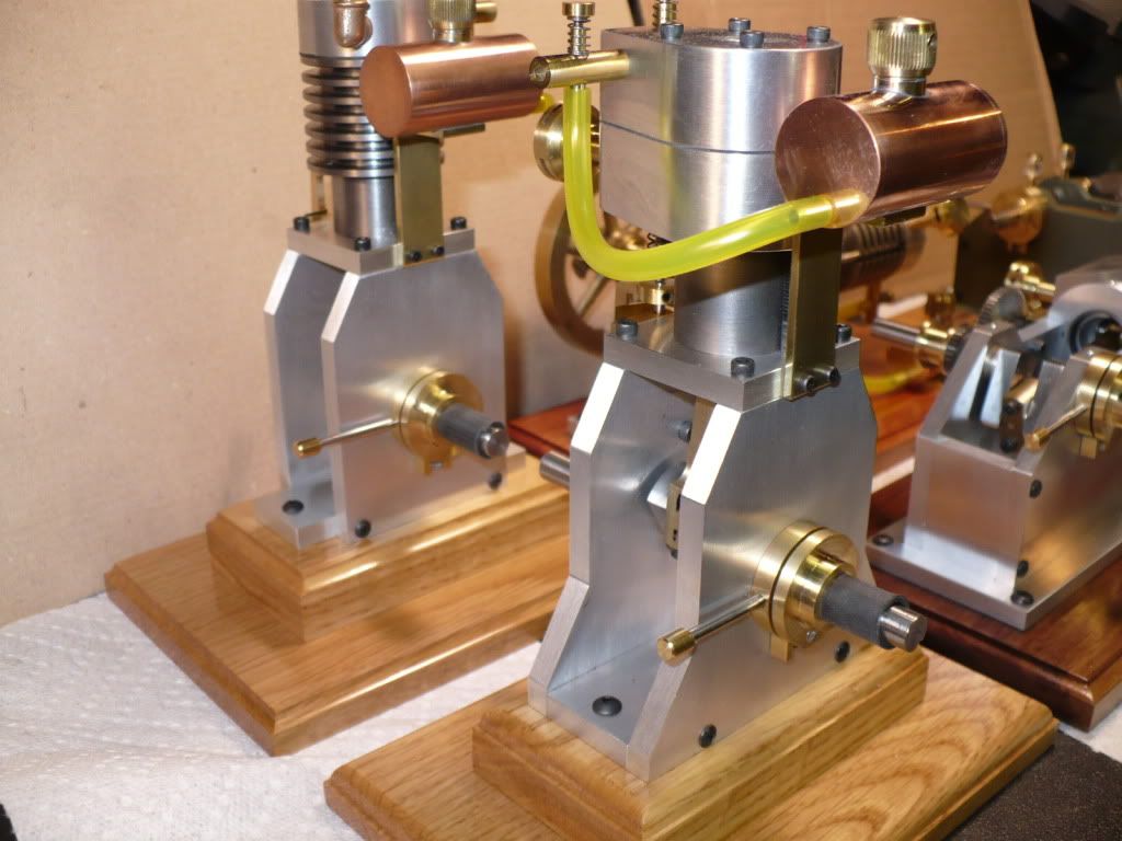
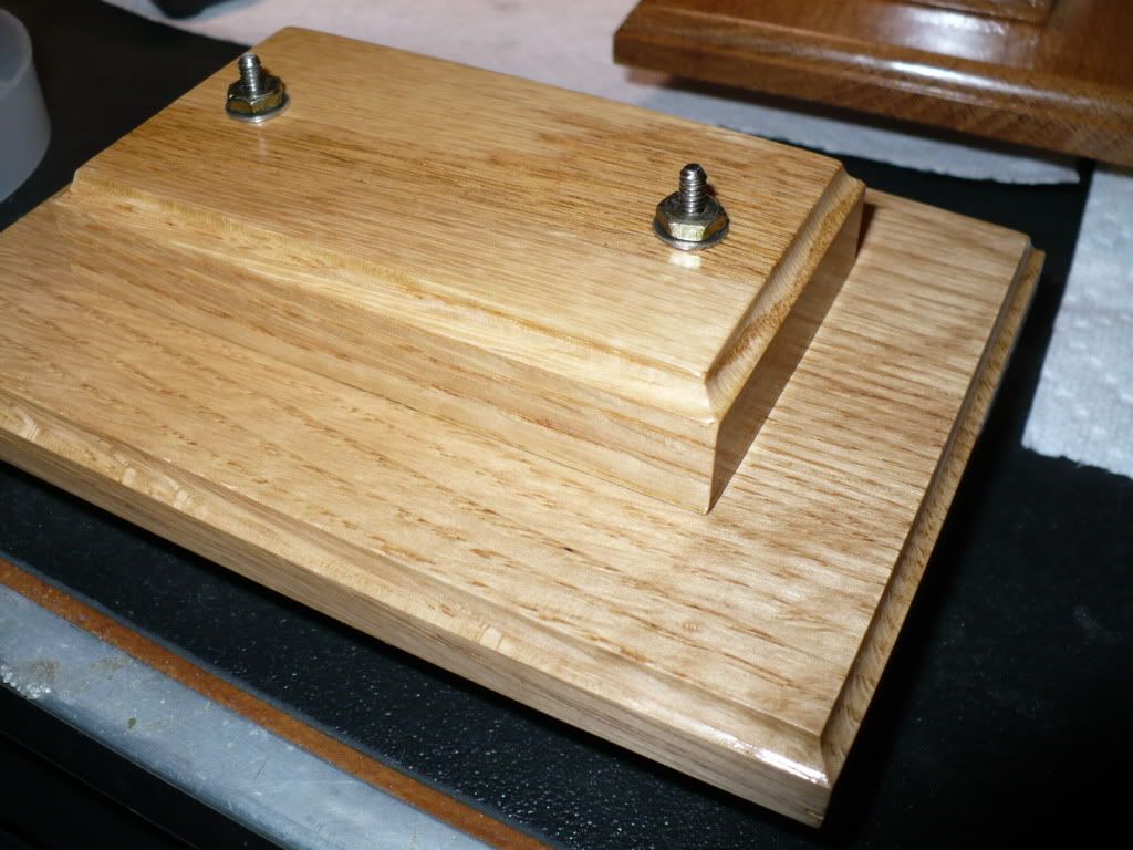
The wood bases are just about finished. I used three coats of sanding sealer, and three coats of satin polyurethane. The two bases for the vertical versions are made of two pieces of oak, a 3/4" block on top of a 1/2" base shown in picture below. With the finish on those already dry I glued one set together with carpenters glue and temporarily bolted them till the glue sets up. 24 hours should be sufficient to remove the threaded rods and use them to glue up the second pair.
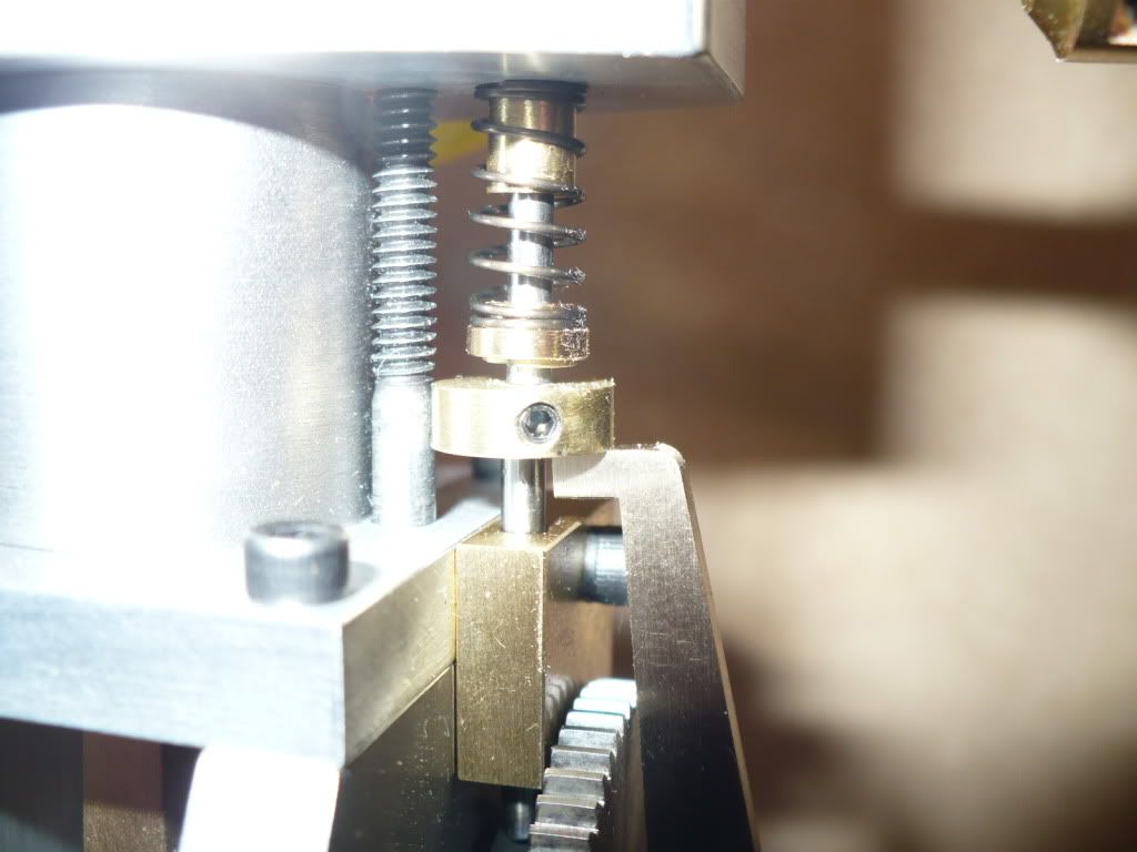
#315 I couldn't understand the drawing and description of the governor weights. It looks like the springs are supposed to be hooked over the ends of protruding 2-56 studs? I deviated from my understanding of the drawing.
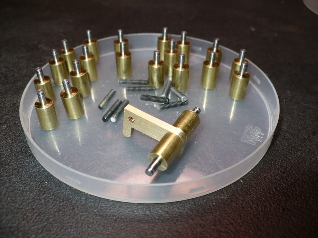
The plan calls for the weights to be .250"dia x .312" long, threaded all the way through for a 2-56 stud to attach the two halves of the weights to the governor arms. I made the weights .250" x .375" threaded 2-56 half way, and reamed 3/32" from the opposite end.
I made studs by cutting off the heads of 10x 2-56 x 1/2" long cap screws. The studs ended up about .440" long which is more thread than needed. I cut 3/32" pins .375" long and added a .020" x .020" groove on each one near the ends to hook the springs onto. The pins are Loctited halfway in with 3/16" showing. This is more than what appears to be 1/8" on the dimension-less drawing. The slightly longer pins eliminate any concern of the spring diameter.
Getting the springs is not going to be really easy! :wall: On the plan it says..."Small hook end springs (2)"

oh:
Two days worth of work, and only two pictures, sorry guys. scratch.gif
-MB




![DreamPlan Home Design and Landscaping Software Free for Windows [PC Download]](https://m.media-amazon.com/images/I/51kvZH2dVLL._SL500_.jpg)


