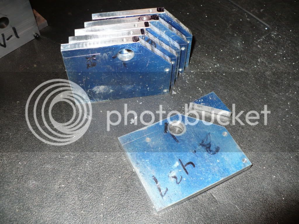
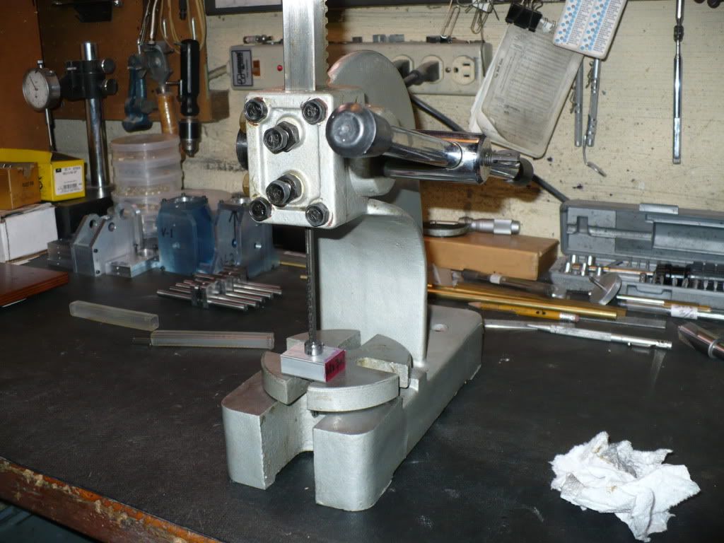
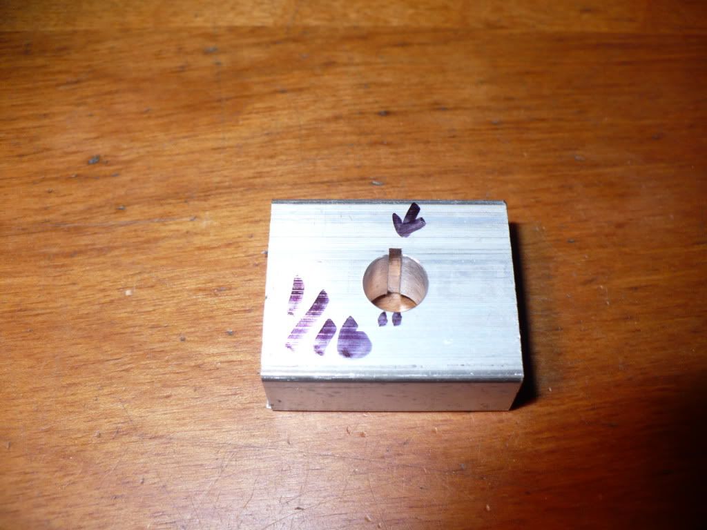
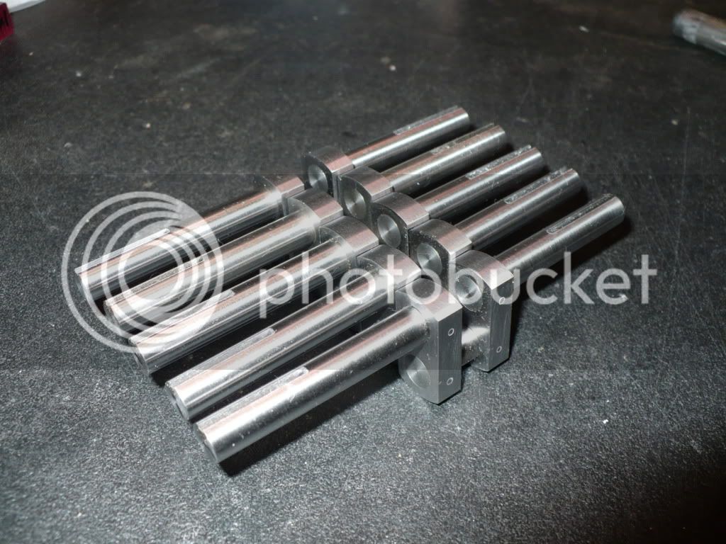
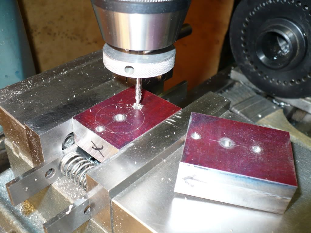
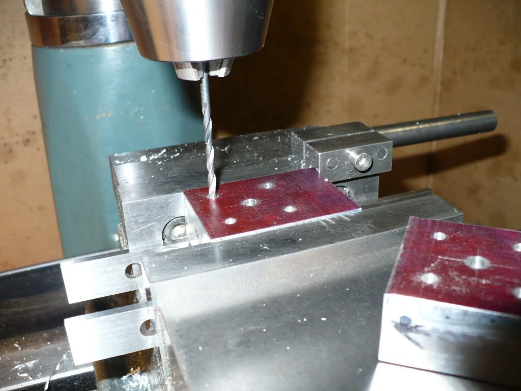
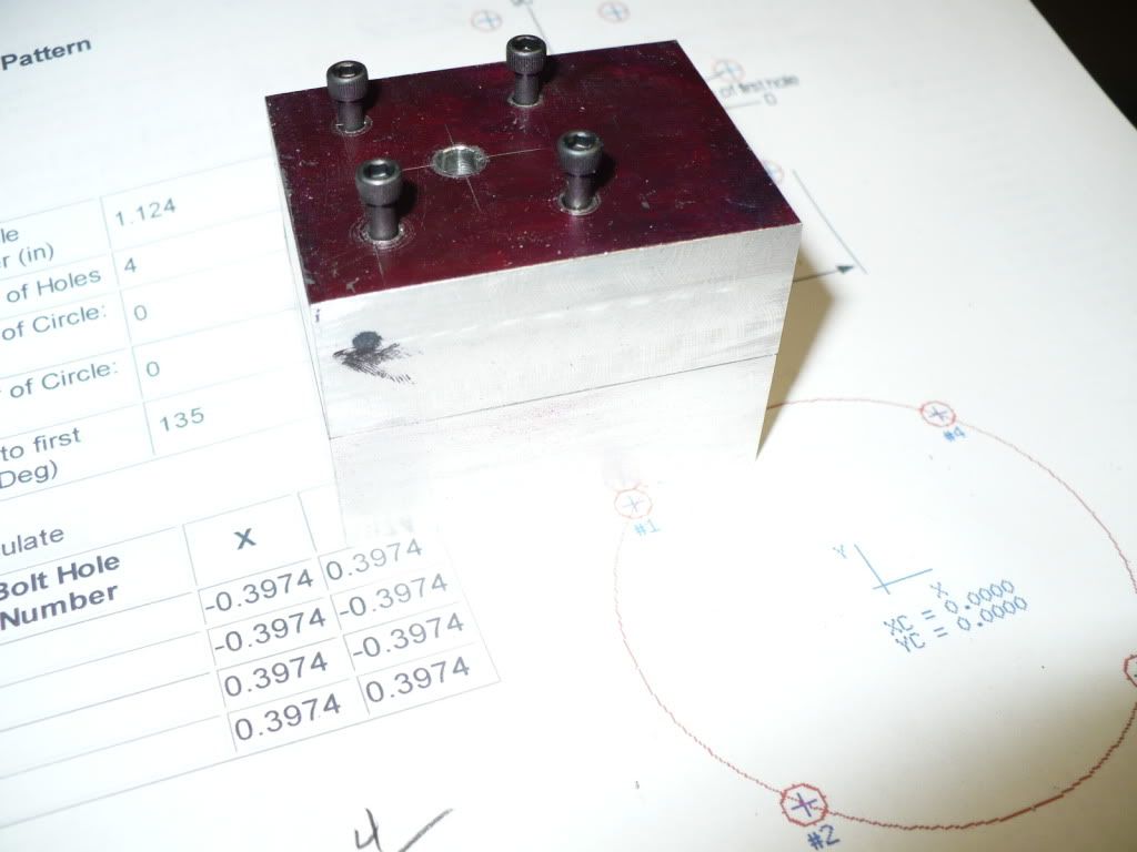
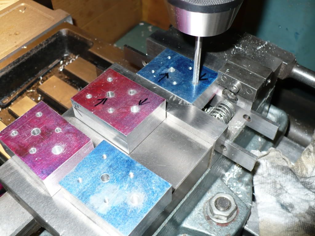
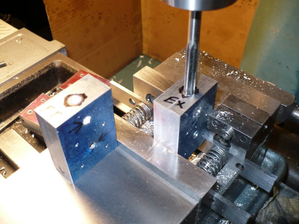
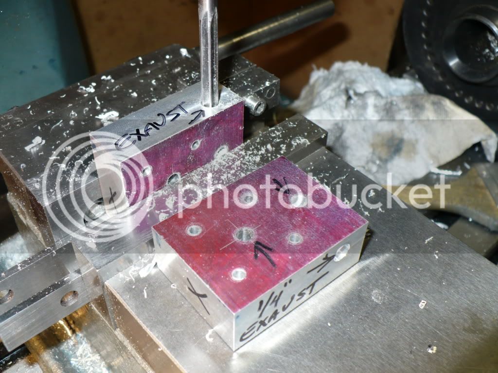
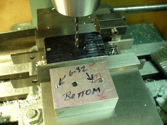
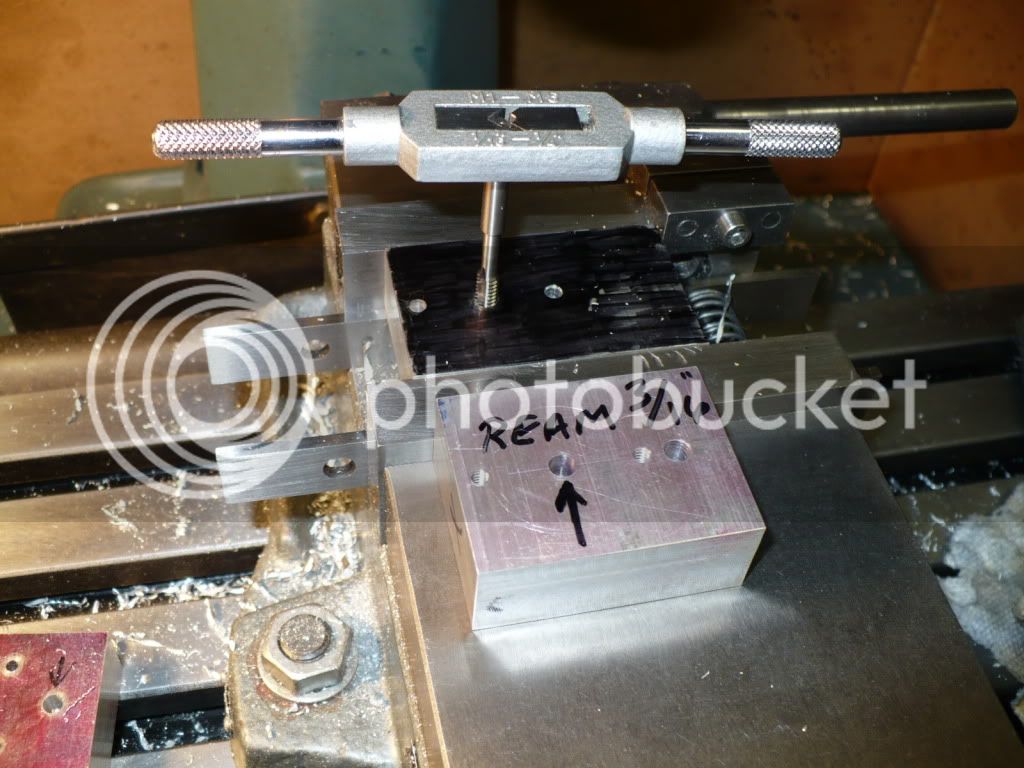
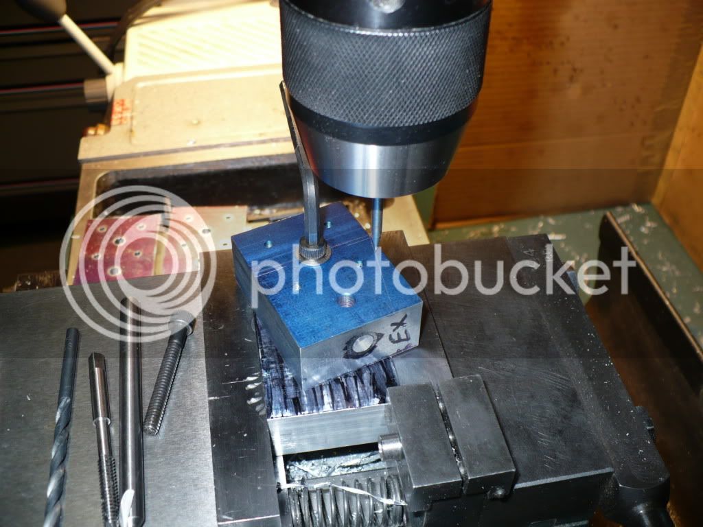
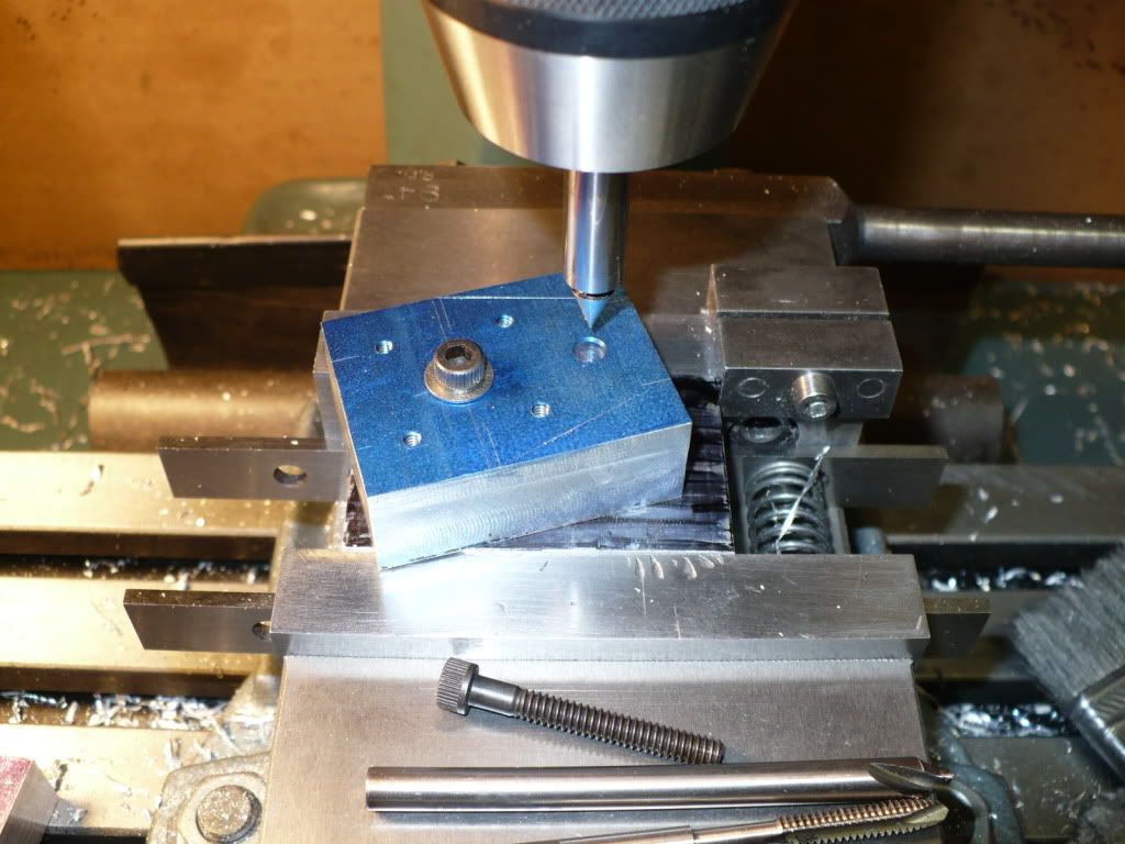
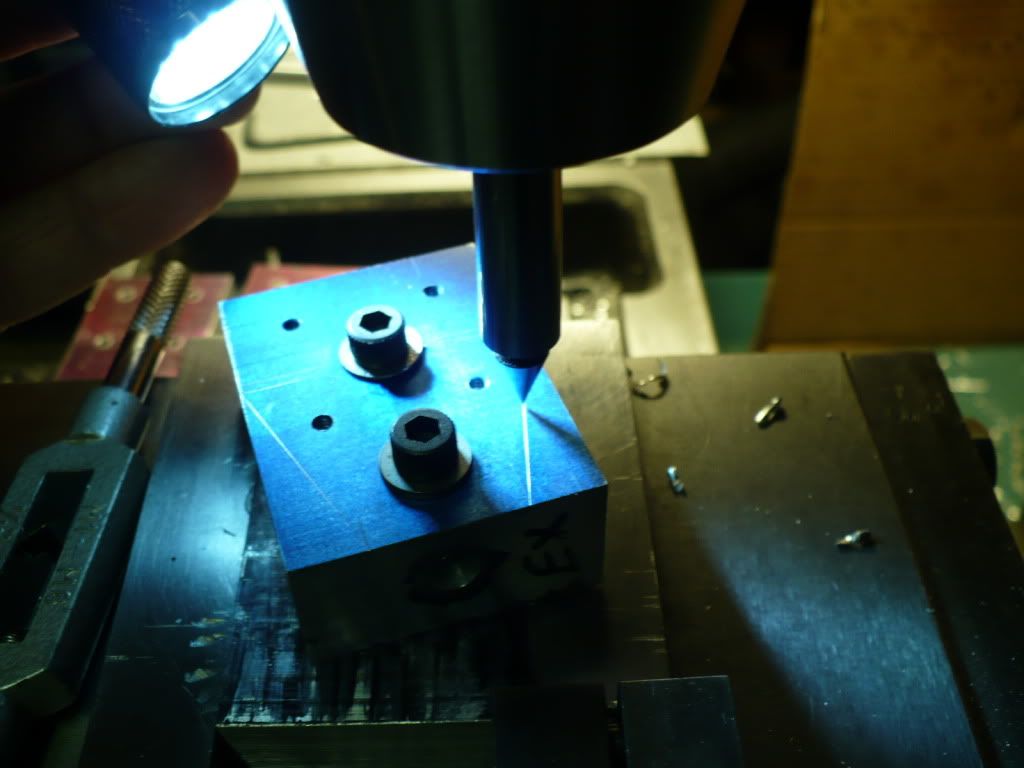
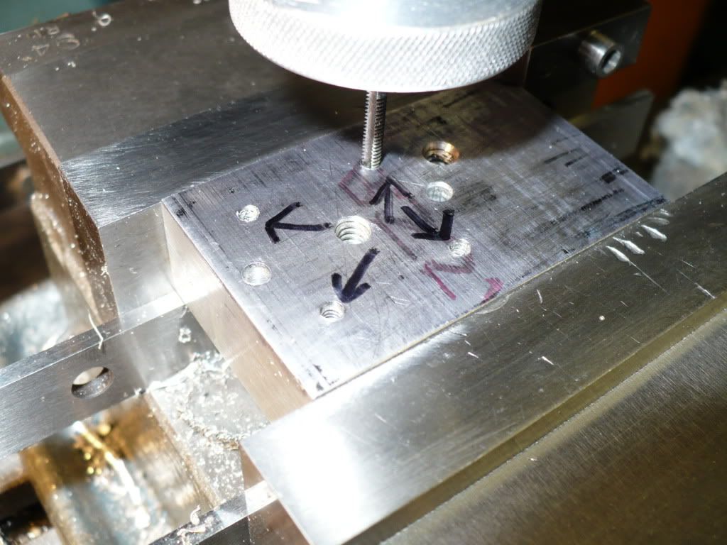
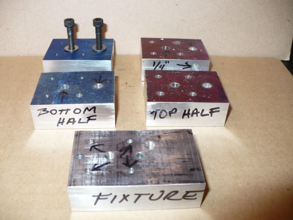
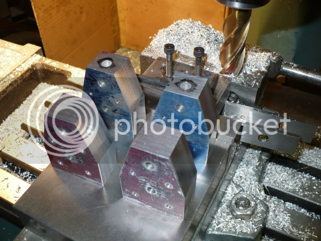
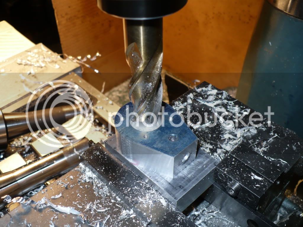
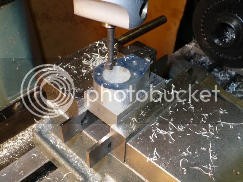
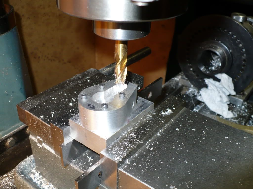
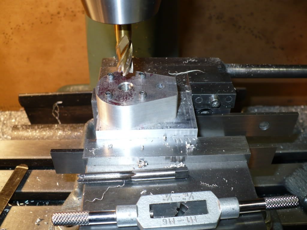
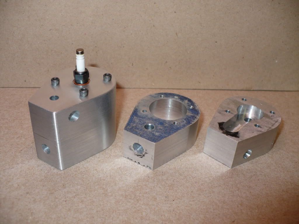
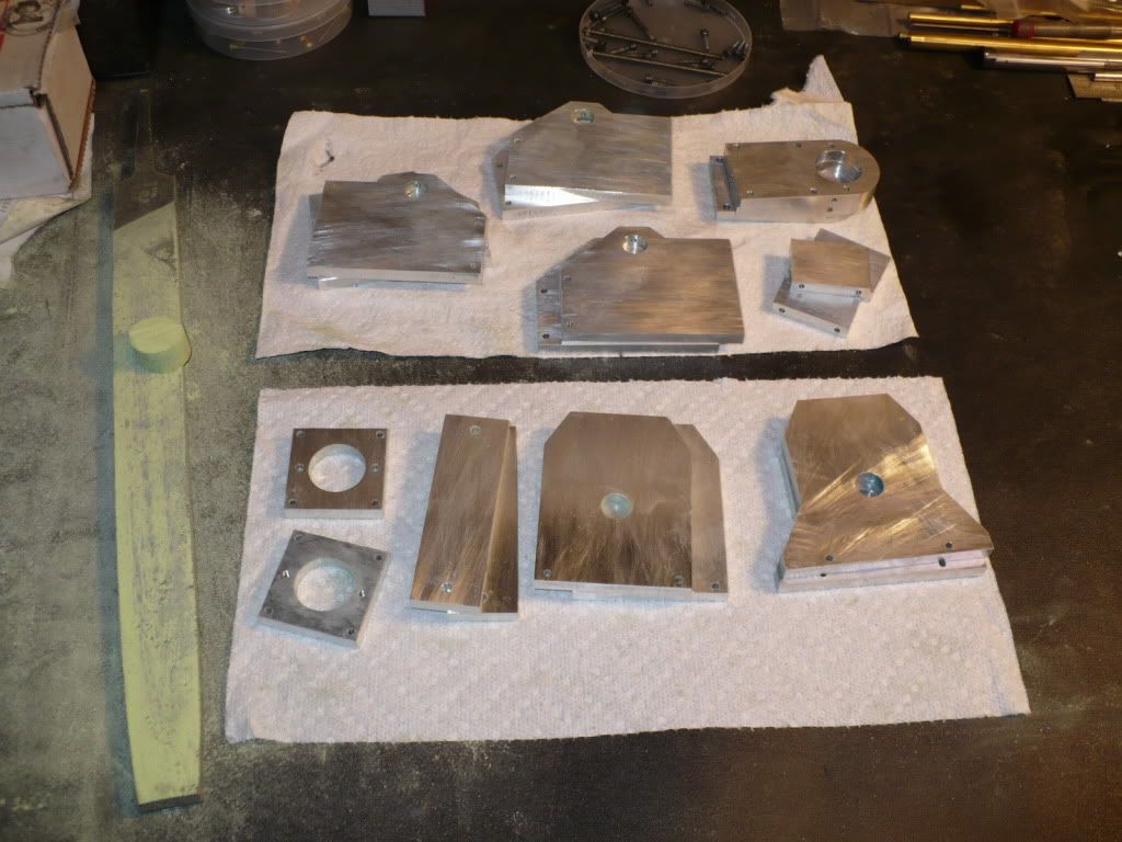
#207 I finished up drilling and tapping the plates for the two vertical versions. I assembled the plates with 4-40 screws and all the pieces fit together well. The only coment I'd like to make is that a #35 drill specified for the thru holes is way too tight, and the screws need to be threaded in before they reach the threaded holes in the mating plates. Adding profiles to all the side plates is next.
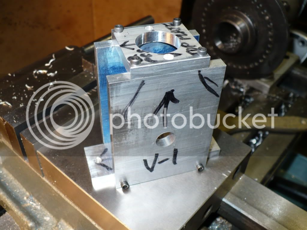
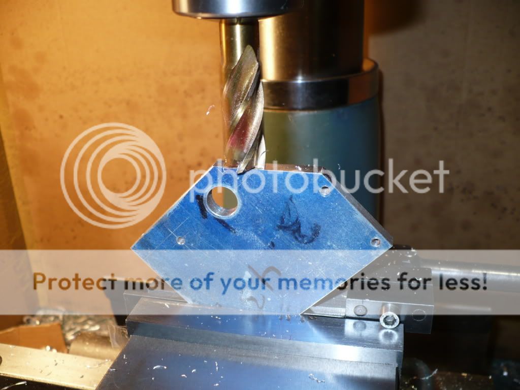
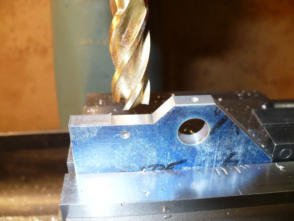
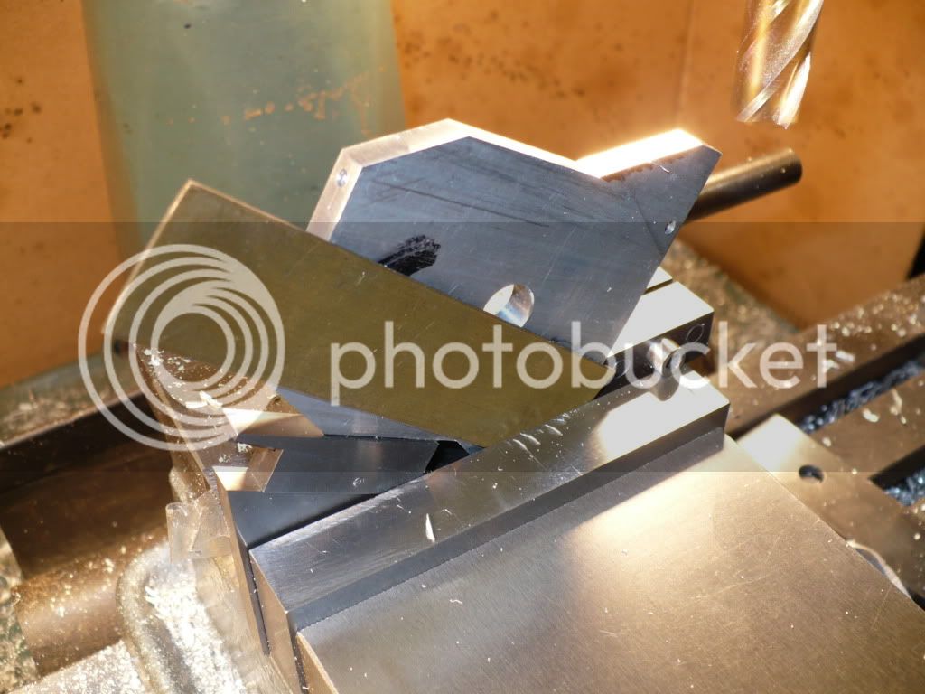
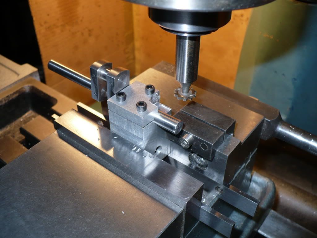
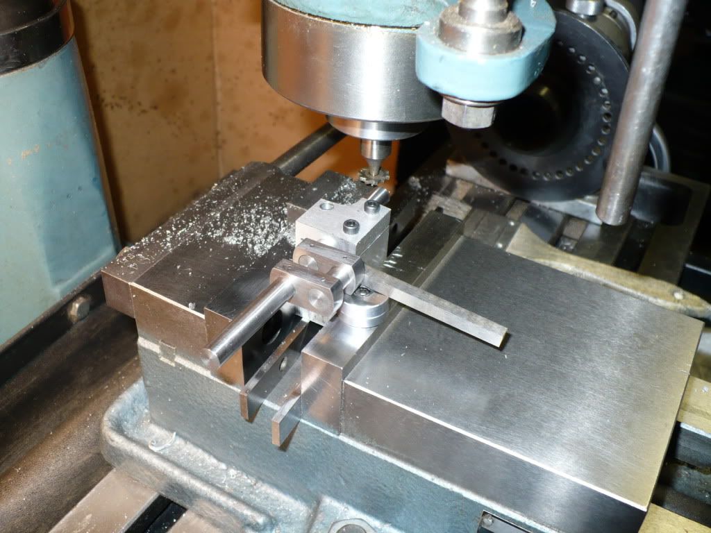
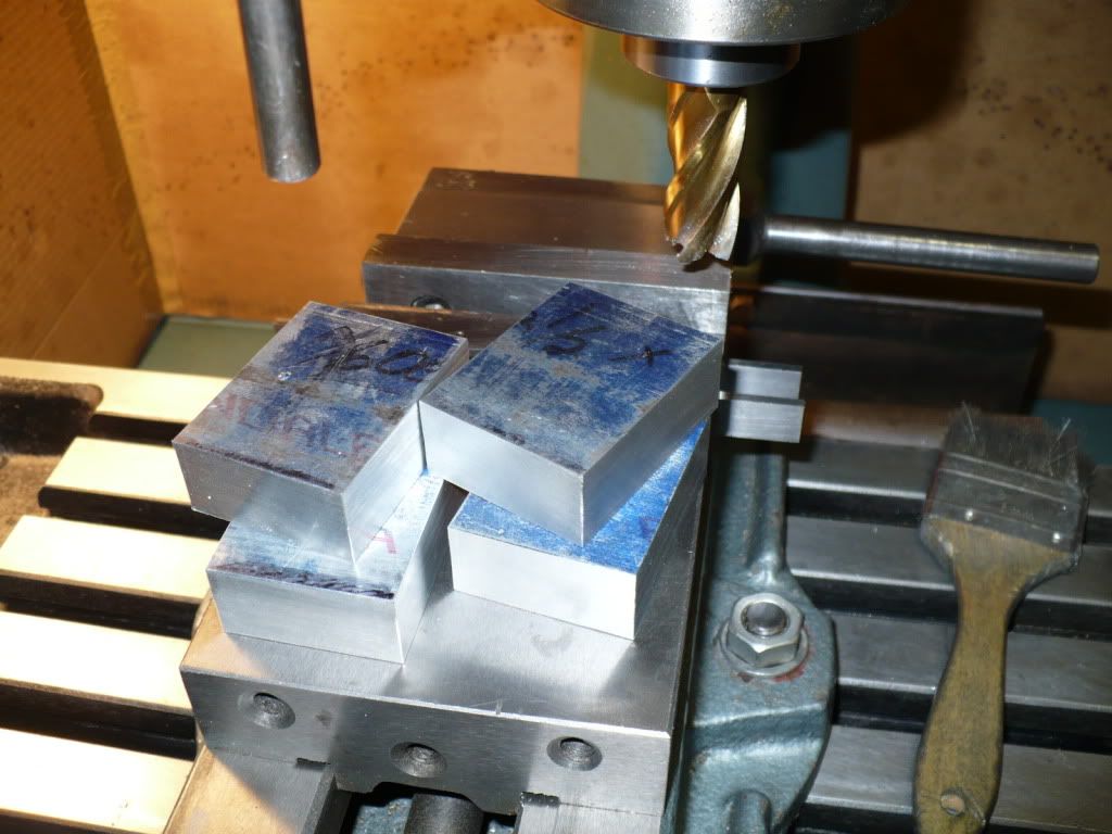
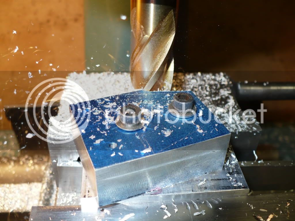
#208 The profile being cut in the picture below is the only one specified in the plans for the horizontal engines. Based on the dimension I used a bevel protractor and determined the profile angle to be between 43-1/2 and 44-1/2 degrees. A little odd, so I went with 45 degrees. I already have a shop made thin 45-d V-block made for my vise. Close enough as far as I'm concerned. In the picture the excess was cut away with the band saw, and touched up with the belt sander. I left only .020" to be milled off. On the front plate you can see the scribed line. I could have easily removed more with the belt sander and finished up with a file. It would have been faster to void a mill set-up, if I were only doing two side plates for a single build.
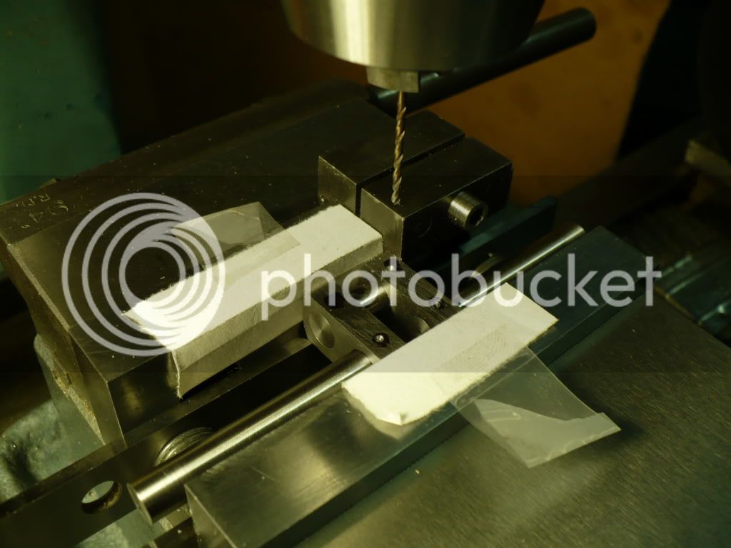
#209 I attached the thin V-block to the fixed jaw of the vise with double stick (sided) scotch tape. After clamping the work piece in the vise, a vise stop was slid into place and locked down for added support.
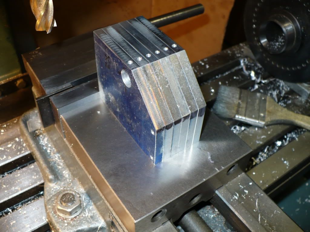
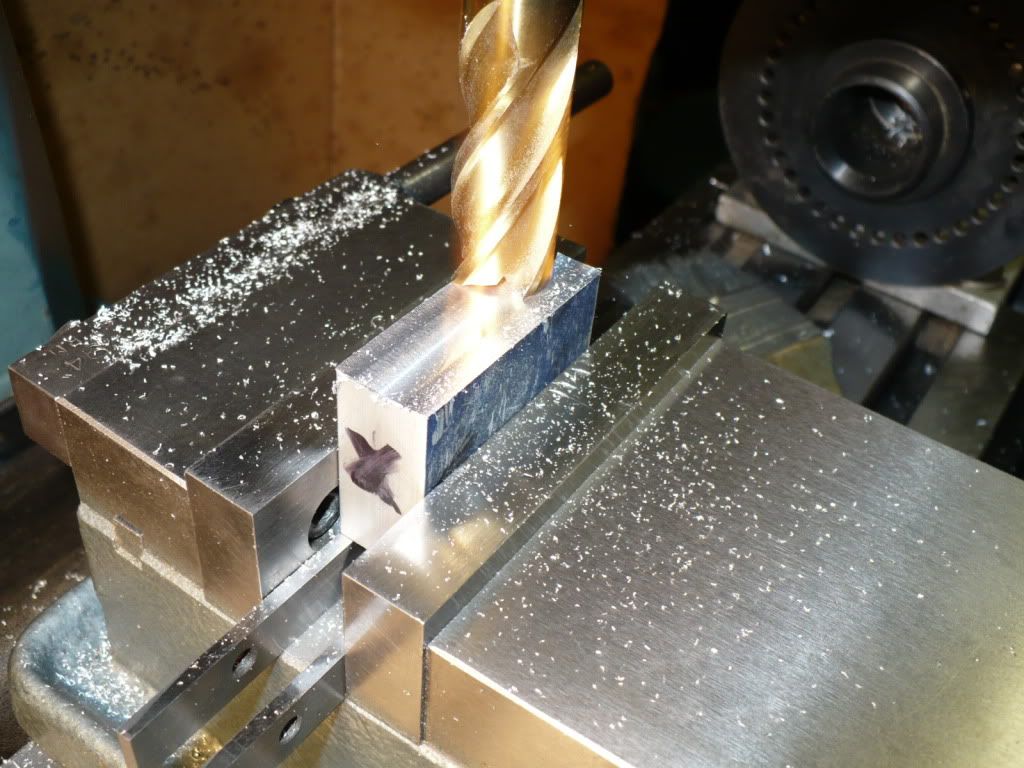
#210 I carefully adjusted the height of the cutter several times on the first piece to get it just right. The rest were cut with one pass. In the picture below you can see the roughly scribed lines I use habitually to avoid gross errors, in this case they were unnecessary.
Chop, chop, in the butcher shop! :big:
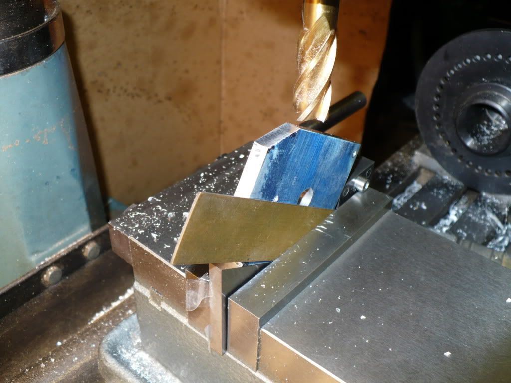
#211 Here's where I deviate from the plan and add an additional profile. Before ordering the plan set I noticed the radius above the cylinder on the front plate was a bit tall and odd looking. The front plate is 1.500" wide with an indicated radius of .937". To rectify this eye catching situation the radius needed to be reduced. A .750" radius would be the way to go, but this would require the side plates to be milled down to the threaded gear mounting hole. A compromise was in order to reduce the radius on the front plate, and the height of the side plates to make them both look a bit more appealing. The final decision was to use a .780" radius, and to reduce the height of the side plates by .280". The reduction in the side plates also allowed for the same angle to be used in front of the crank shaft bearing points, adding a more symmetrical look to the side plates.
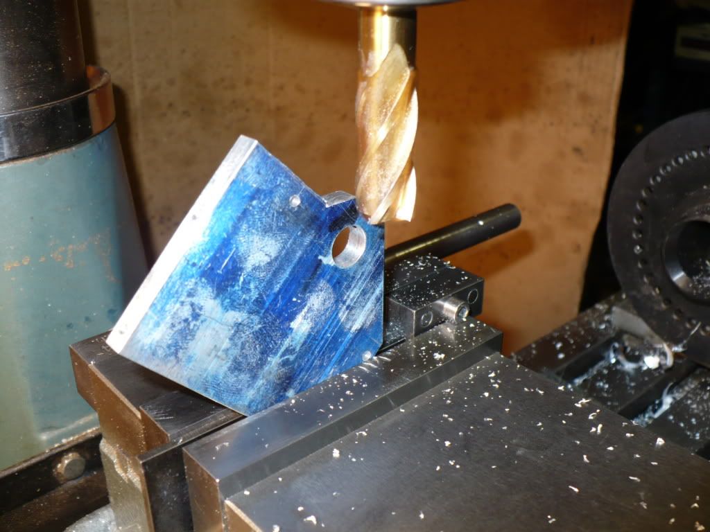
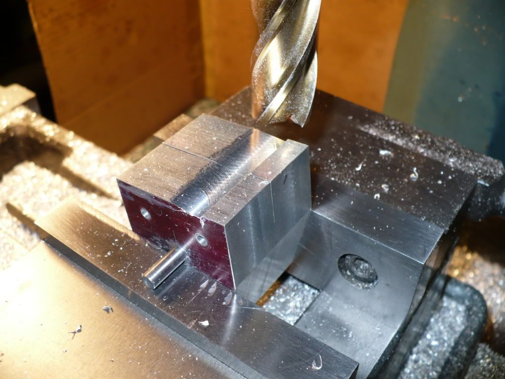
The lay out was simple. A tight fitting pin was used to line up two plates, with the top plate flipped over the angled line was scribed on one plate to set the cutter at the proper height.
#212 I used the top of the plate at the bearing point to zero out the mill quill and lower the cutter to the proper height. On the first plate I moved the cutter towards the milled angle till the intersection was just right. Using one cut along the Y axis all of the plates were cut in identically. After they were all cut up to the angle with one pass, the plates were returned to the mill to finish up with the rest that wasn't removed with the critical first cut.
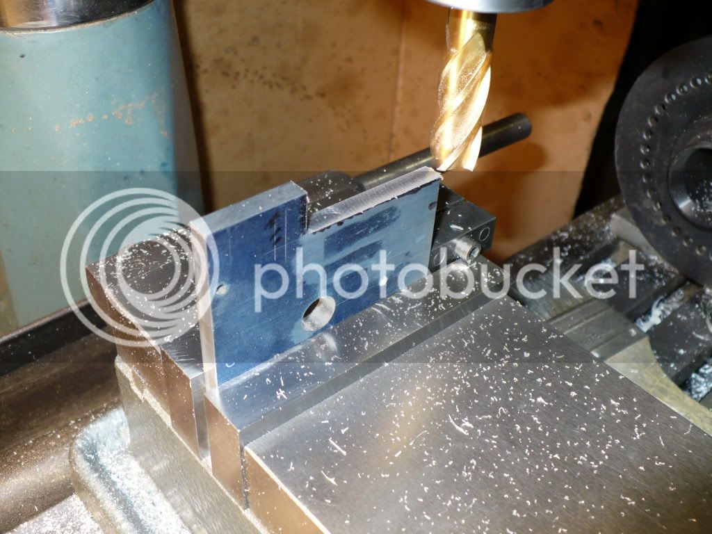
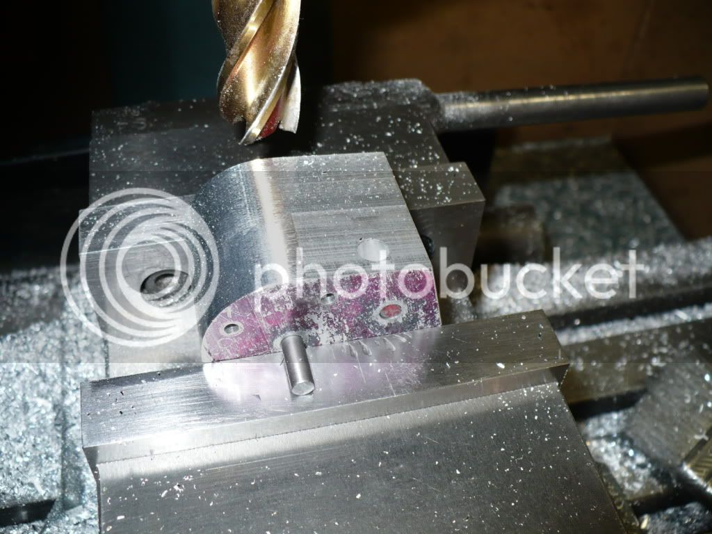
#213 The plates for the vertical (V-1) have a simple 30 degree profile cut on both sides. I had to use shim stock to get a grip on the work, since the angle plate was thicker than the work piece.
Its always something causing a problem! :wall:
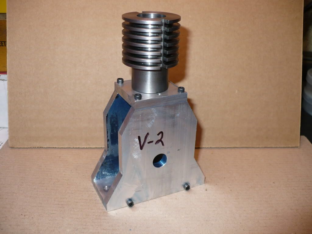
#214 The side plates for the vertical (V-2) version just begged for an alteration. I made the plates the same width as the length of the base plate. The next step was to reduce the upper part of both plates to the original width.
Your probably thinking, "This is one crazy machinist, first he makes it big, then he cuts it up and makes it small!" Rof}
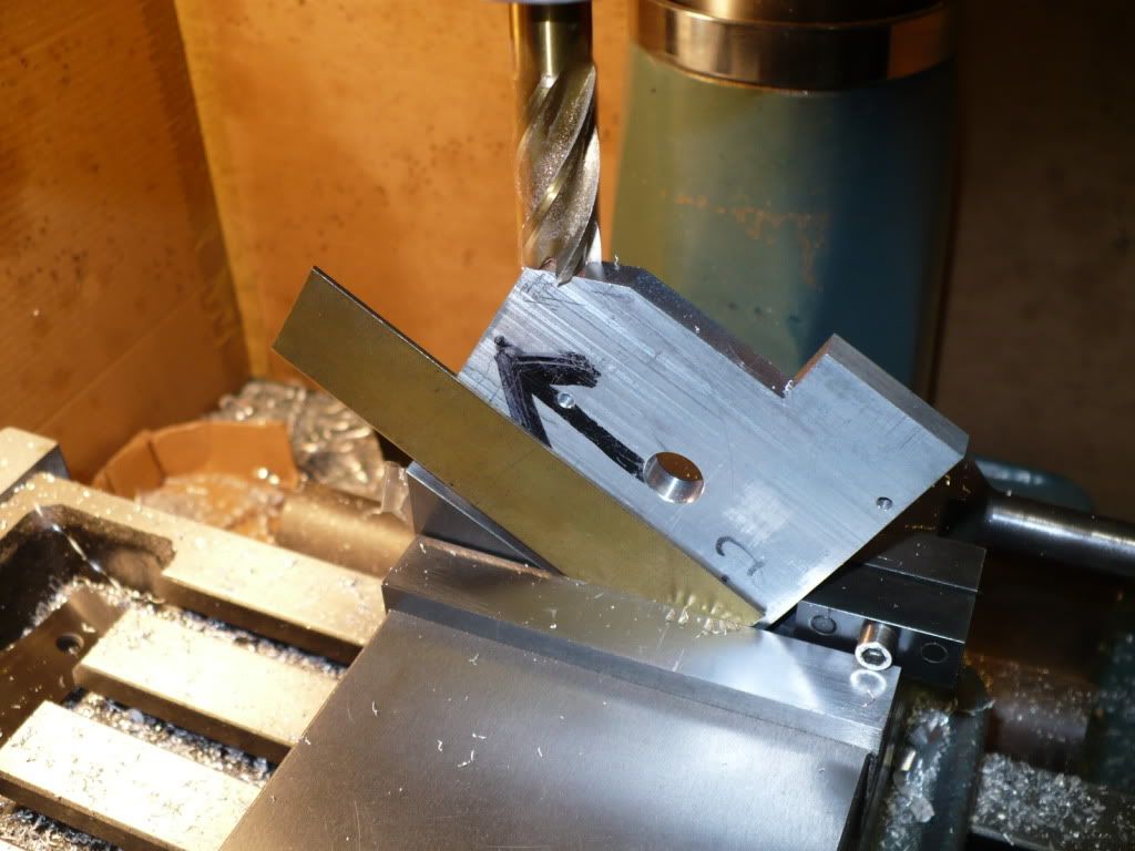
#215 This is where things got interesting. It was getting late and I was starting to feel a little 'punch drunk'. I was scribing lines all over the place and getting seriously confused! I should have quit while I was ahead, but no the "I feel lucky" attitude took over. I forged ahead by milling the 30 degree angles first.
#216 The upper angles went well. The next steps were to cut the lower 30-d angles. After cutting the first one I went to flip over the work and reality set in! I had milled away what little support the lower section of the work piece offered!
Now your thinking "This is one stupid machinist!" Rof} But I had planed on using an adjustable parallel to support the work. :idea:
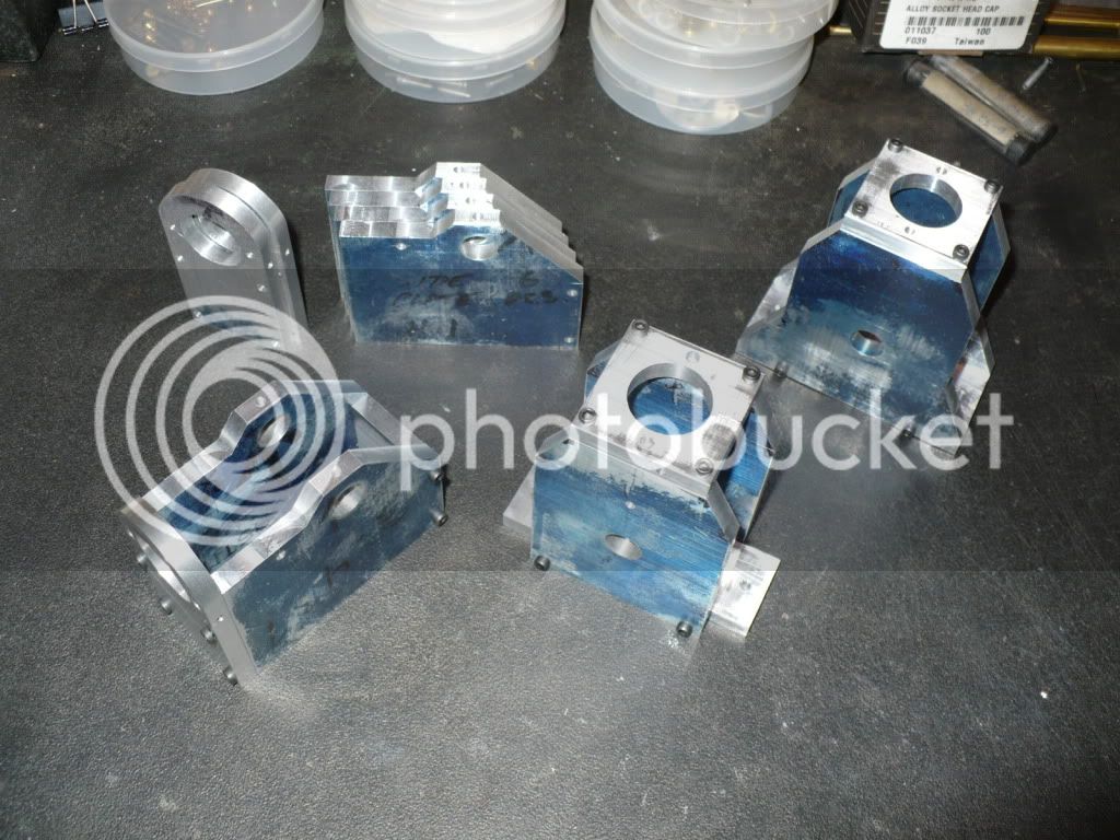
#217 Here's a group picture of yesterdays shop adventure. The lay out blue that missing from the pieces is not lost, its all over my hands! :

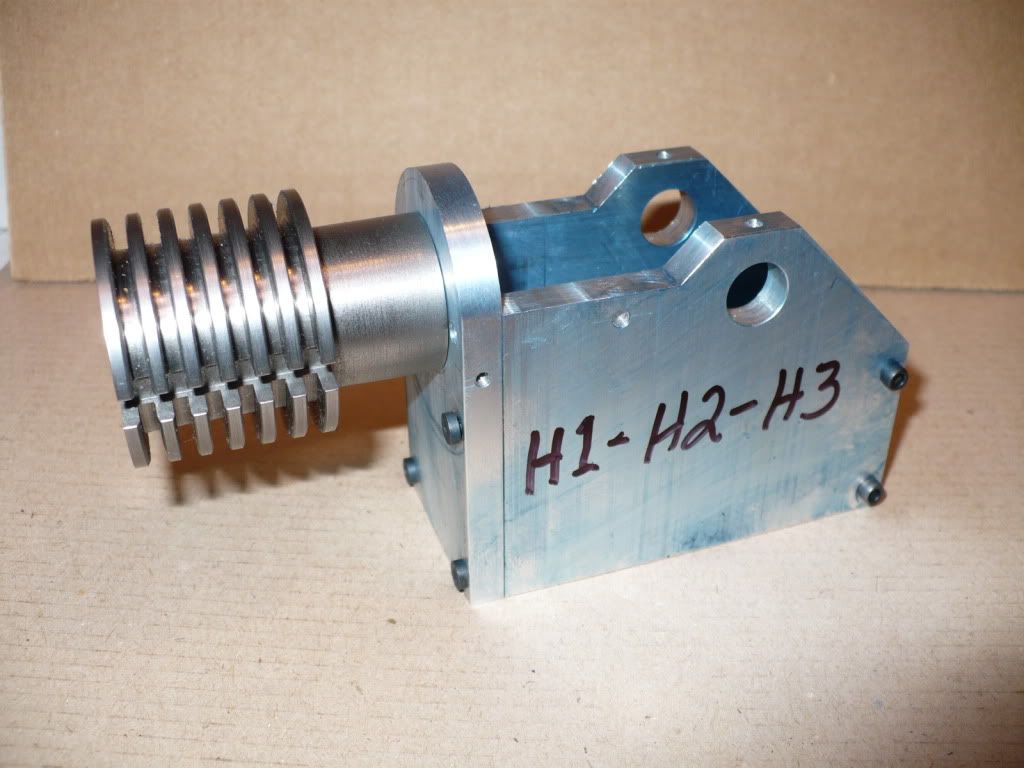
#218 Here's a better close up. H-1, H-2, and H-3. I know you guys like pictures.

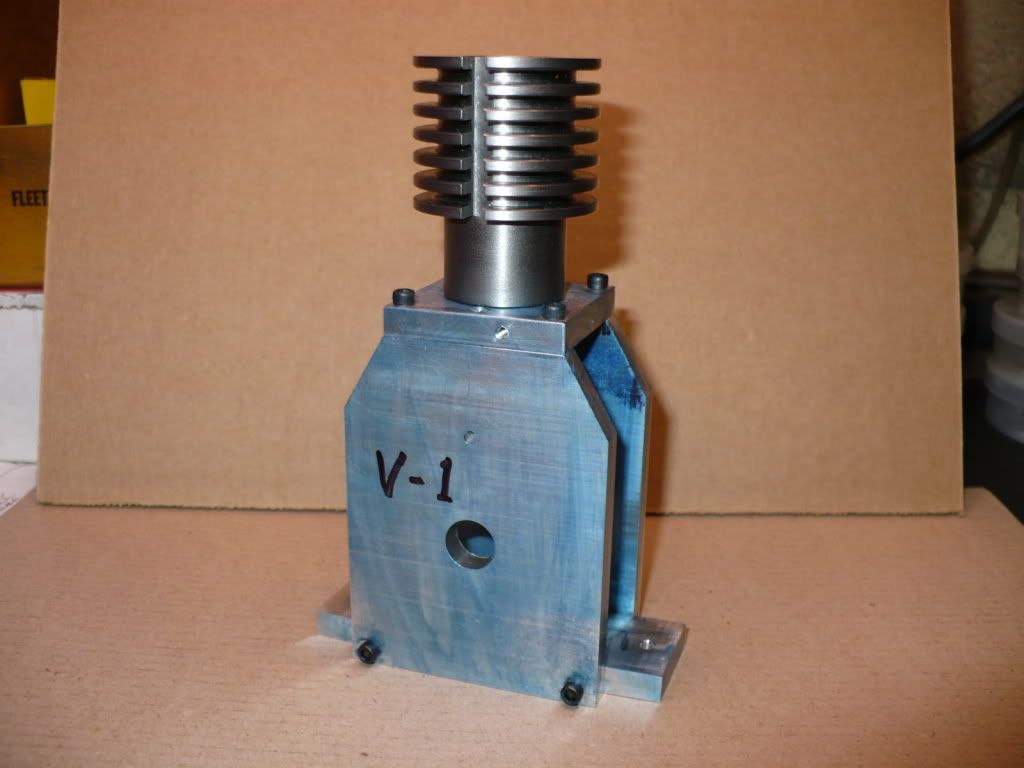
#219 V-1 side plates as drawn in the plan set.
#220 V-2 My modified side plates, no plan at all, really. Slice and dice, just like a Butcher. Rof}
-MB ;D


![DreamPlan Home Design and Landscaping Software Free for Windows [PC Download]](https://m.media-amazon.com/images/I/51kvZH2dVLL._SL500_.jpg)


