Making a Face Parallel to a Bore

Home Model Engine Machinist Forum

Help Support Home Model Engine Machinist Forum:

This site may earn a commission from merchant affiliate links, including eBay, Amazon, and others.

Antman

Well-Known Member
Joined
May 9, 2009
Messages
255
Reaction score
9
Hi Guys,
I’m really stymied this time and have no idea of how to do this. I want to make a bearing block for a horizontal shaft. One face of the block must be flat and that flat face parallel to the bore, so that when the block is bolted down, the shaft runs horizontal. Boring, no problem, facing also, but how to get them parallel? I know that this should be a basic technique to get right before I ever make engines.
Thanks yet again,
Ant
 
Ant, a sketch might help - like what are the sizes and is it a split block etc.

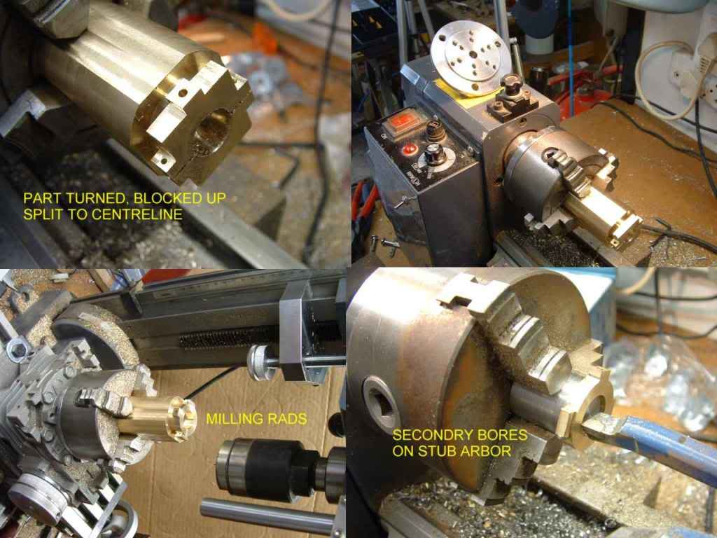
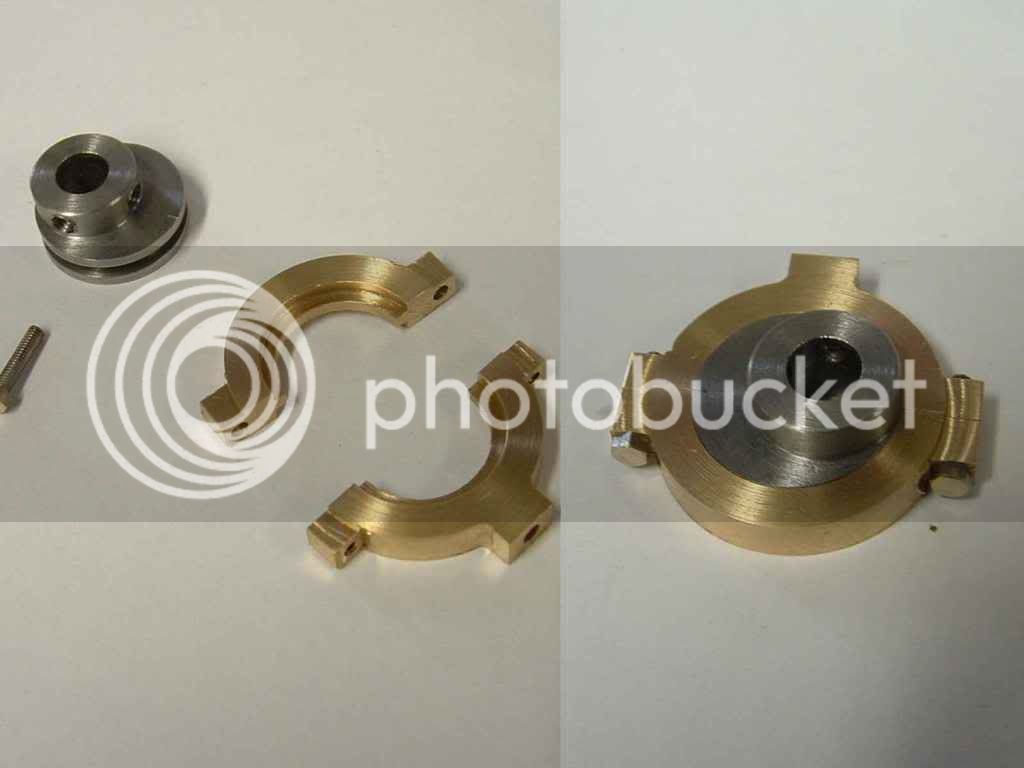
I made the split blocks for my beam engine by making a disk in the lathe not fully parted off - took that - chuck and all to the mill - used a slitting saw to split it on the centreline (one face bang on centre) did the drilling and tapping for the bolts - cut off the "top" half of the cap and bolted it back on - back to the lathe - did the bore - back to the mill to finish off all the base face, shaping etc - back to the lathe to part off (could also have milled it off.).

This being a small part this was an appropriate method - but there are many ways you could approach it.

Did the eccentric cam much the same way

cambigend1.jpg


CBIGENDASSY1.jpg


ken
 
Ant,
I did a set of engine bearings like this:

cut the block square but a little oversize, put in vice and drill/ream for the shaft , take out block, put shaft through hole and put block back in vice with the shaft resting on the vice jaws, mill flat to size.

Of course this depends on the vice jaws being the same height and the mill head being trammed right.

Ian
 
Here's one possibility.

1) Face and bore your block; face should be perpendicular to the bore
2) Clamp in milling vise with face down on parallels. Use side flutes of mill to create surface parallel to the bore

If by chance you use a 5C collet to face and bore the work, then just move the collet to a collet block, chuck the block in the milling vise, and mill your surface that way.
 
Another way would to be to face off the bottom and drill the holes that will be used to mount the bearing block. Then bolt the block to an angle plate then face it off and bore the bearing hole.
 
Thanks guys for putting up with me. I feel really stoopid. My mind just boggles when I see work like yours, Ken, your concepts, your working models, the beautiful little bits and pieces. I can only wonder at their accuracy. So I’m really not far along with this machining thing and my progress is really, really slow and now I see that for a little 2 stage operation my tools are seriously wanting as well. All I basically want to do is bore 16mm x 39mm in a block 39 x 46 x 55mm and have the bore parallel to one side.

So I guess what I should be posting is how to totally rebuild my mill .

Portlandron, thanks so much for your answer and sequence of operations. I suppose that would be the most accurate way of doing it as well. So all I need now is a faceplate that runs true (well, it’s a lot better than my mill) and a small angle block. Home made cylindrical squares?

Thanx
Ant
 
Antman said:
Portlandron, thanks so much for your answer and sequence of operations. I suppose that would be the most accurate way of doing it as well. So all I need now is a faceplate that runs true (well, it’s a lot better than my mill) and a small angle block. Home made cylindrical squares?

If you run an indicator down the your mill's fixed jaw face you should get a feel to how square it is to the mill spindle. If you don't see more than .001" of so in 2" of travel you should be good to mill that edge.

As for the faceplate - I'd mount it in the lathe and check it with an indicator. If it's all wobbly it can be trued up with a pass of the cross slide in a facing cut. If it's not flat after that (and if your lathe is worn it will not be) you should be able to tweak in the cut to cut it flattish or to scrape the faceplate flat in the area that flatness is most lacking. The process is pretty enlightening and tells you where your lathe is least accurate.

All in all you may be trying to squeeze more accuracy out of the process than you need. It's not uncommon, I do it too, but there are a lot of places that we try to be a lot more accurate than is really needed. Most things don't need the accuracy we try to give them.
 
You didn't provide much detail so I will make a couple of comments guessing on your project.

If you are making two bearing blocks for a shaft with what is usually referred to as a running fit, they have to line up very accurately.

If it is one block with a long shaft sticking out the bore and base has to be very close on parallel or the shaft will be out of line magnified by the error in parallelism.

In either case I would use the shaft in the bore to get the block level under the mill. Put an indicator in the mill spindle and get both ends of the shaft level. It is easiest if you have the block in the vice so that you can tap it gently until the shaft is level.

If you have two blocks, clamp them directly to the mill table with the shaft free to rotate and mill the two flats.
 
Ant, Re Stan's comment on making two blocks - if you use my method (or something similar) make both blocks at the same time (ganged up one behind the other) that way the height , alignment and any offset should be identical.

ie make them as a pair and mark them so you know which way arround they go - all my blocks are marked x1:x1 etc. on mating faces where they won't be visible after assembly.

Ken
 
Thanx guys for your replies. On this side we have a long weekend and some of the kids came home so no shoptime and no thinking about how to do my bearing block. I'll get back to you if I make some progress.
Ant
 

Latest posts

Back
Top