Kozo A3 in 1.5" scale

Home Model Engine Machinist Forum

Help Support Home Model Engine Machinist Forum:

This site may earn a commission from merchant affiliate links, including eBay, Amazon, and others.
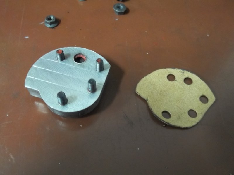
Gasket is a paper-based material I got at Ace Hardware. Coated with a mixture of steam oil and graphite. I used the same stuff on all the gasketed joints without any problem, other than this one. Since the plate was loose I suspect that steam or water got underneath and split the gasket.
 
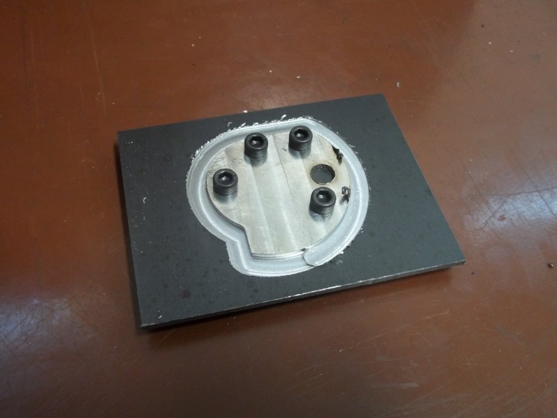
After the last post in May I took a break from the A3. But now that it's cooler and steaming is more comfortable, I decided to try to fix the throttle leakage. The plan is to cover the channel in the bottom of the throttle baseplate so that there is more "meat" in the paper gasket.

The cover is a plate made from some 304 SS sheet that I machined down to .065" thickness, Drilled the mounting holes on the Bridgeport and then the profile on the CNC mill. To keep the throttle rod at the same height I took .06" off of the bottom of the throttle.

large.jpg


I then fastened the cover and baseplate together with red high temp RTV (good to 600F). Then made a new paper gasket and reinstalled everything in the steam dome,

large.jpg


Hope to retry the hydro test on Wednesday; if I succeed may fire it up too.
 
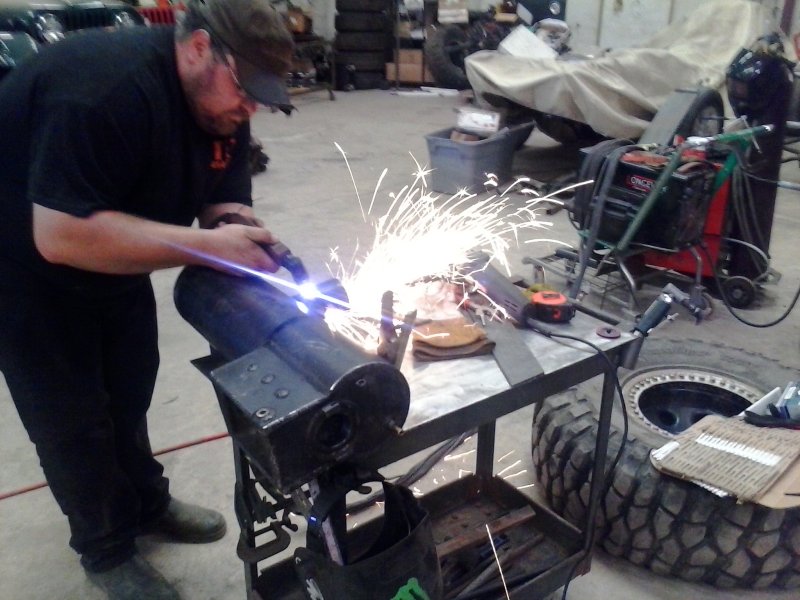
After many attempts to seal the throttle plate with various types of gasketing, I've decided to cut off the steam dome. A plate with a channel between the dry pipe and the valve mount will be remade and welded to the top of the boiler, and a removeable steam dome will be fabricated.

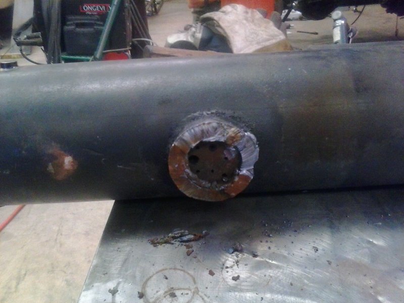
First stage of rebuild is to get rid of the old dome, which is welded to the boiler. Buddy with plasma torch made quick work:

large.jpg


large.jpg


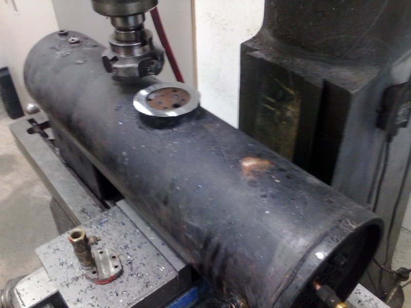
Got it home and applied face mill to clean up the cut.

large.jpg


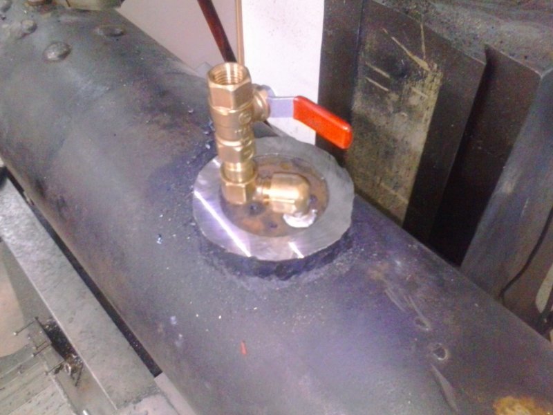
The dry pipe is threaded 1/4 NPT, so I tried this setup. I think it should work.

large.jpg


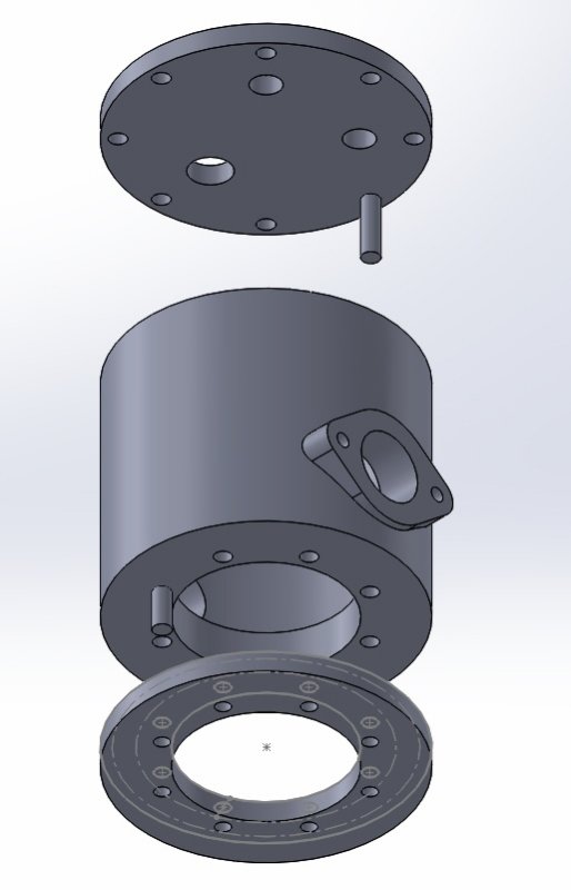
John from the club has some steel pipe that's 3.5" OD and 3/8" wall. I redid the SW model to use a flange inside the dome for attaching to the boiler, and it appears everything will fit:

large.jpg


Bottom disc is welded to the boiler plate and then drilled and tapped. An almost identical piece is welded to the bottom of the main pipe, and drilled clearance to match. The flange for the throttle pipe is welded to the main pile, and then the holes are drilled. The lid is drilled for clearance holes to match the tapped holes in the upper edge of the dome, and the lid has NPT tapped holes for the safeties and for filling the boiler.

The new dome will be slightly taller than the old, as well as wider (old OD was 3.25"). With the old mounting plate not covering the top plate of the boiler I plan to drill an extra steam supply hole as the two small existing holes will be somewhat blocked by the flange.

The throttle tube and turret will rest slightly higher than before, meaning a good opportunity to redo most of the piping. Given that the Superscalte Economy injectors are lifting, it makes sense to place them in the cab where the drain pipe is visible.
 
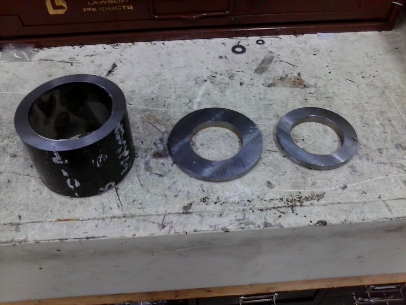
Machined the mounting ring for the steam dome. It will be TIG welded to the boiler, then drilled and tapped. Show in position:

large.jpg
 
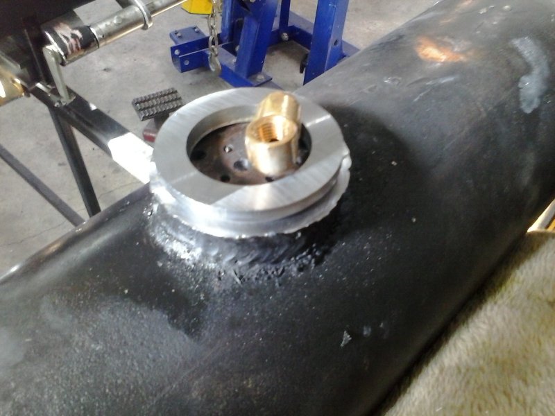
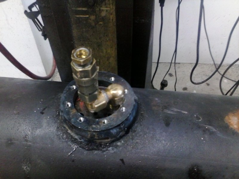
Got the welding done by a buddy. Here's the base ring welded to the boiler, drilled and tapped:

large.jpg


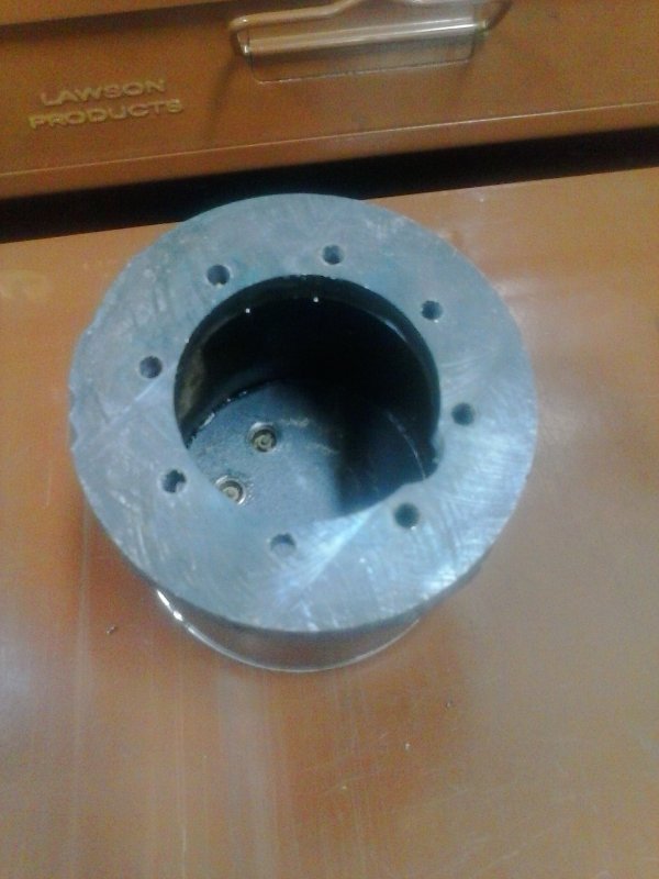
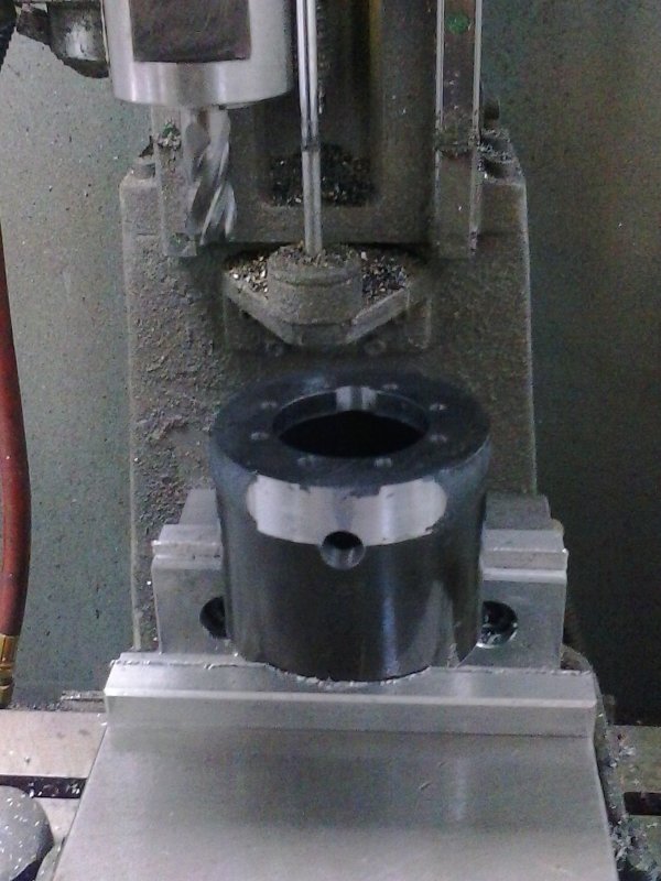
A view of the bottom ring of the dome body, drilled to match the base plate. The notch is to clear the elbow.

large.jpg


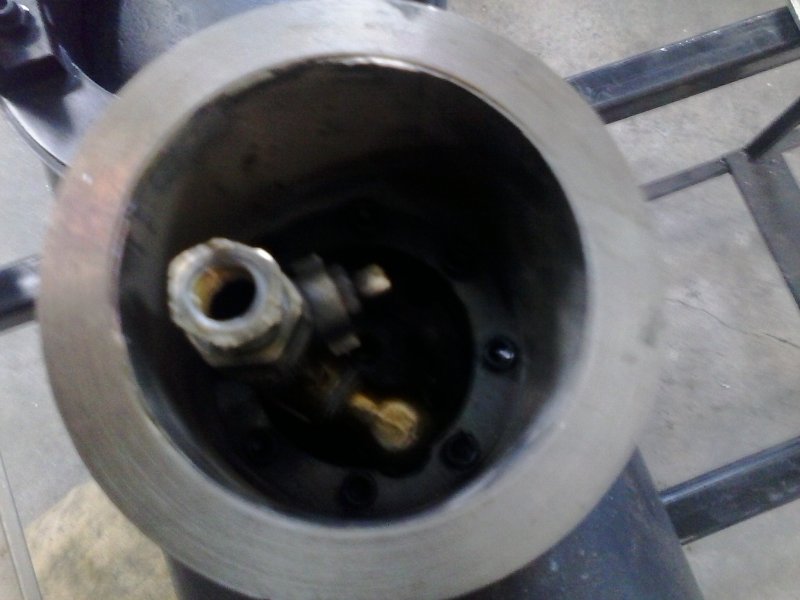
An interior view:

large.jpg


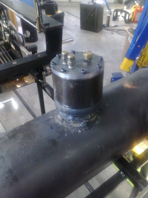
Mounted on the boiler with the lid; safeties and fill plug installed.

large.jpg


Next is to fabricate and weld the mount for the throttle tube.
 
Short shop sessions today. First, measured and drilled the hole in the dome through which the throttle rod will pass. It's 1/2", but could be enlarged is needed.

Then setup on CNC mill to smooth welds where the mounting flange will be welded later.

large.jpg
 
Made the mounting flange for attaching the throttle tube to the steam dome.

large.jpg


The 1/2" drill bit will align the two parts together for welding.
 
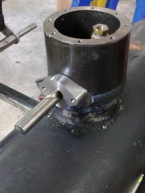
A friend welded the mounting flange to the dome body, so it was time for some fit checking:

large.jpg


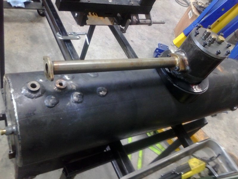
With a little fettling I got the dome cover and base to fit, although I need to install the boiler jacket to be sure. When I installed the throttle rod mechanism onto the rear of the tube I found that the crank for the valve stem is now too short since the valve sits slightly higher now. I had made the hole in the dome smaller this time (.5" vs .65"), so enlarging the hole may work vs. making a new crank.

Since I'm going to redo the piping and since the Superscale injectors are lifting, I will position them inside the cab rather than underneath the running boards. Test fit of the cab looks fine for this by eyeball inspection.
 
I have validated the new throttle assembly via a hydro test to 150 psi last week, and am starting the re-assembly. Had to order some stuff from PMR and McMaster. Got the boiler jacket on and the boiler on the chassis. The good news is that the throttle tube is the same height as before and the cab still fits.

The smokebox piping will be SS steel tube, since I was advised that coal flue gas will quickly erode copper.
 
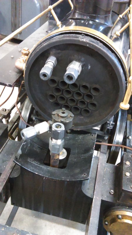
My stainless compression fittings and tube arrived from McMaster. The fittings are longer than I imagined, and a quick fit to the loco revealed a few problems.

large.jpg


The one on the steam port on top would interfere with the petticoat, and on the bottom is a tight fit to the blower nozzle. The connection to the blower nozzle is close the inside wall of the smokebox and would mean a tight bend on the tubing.

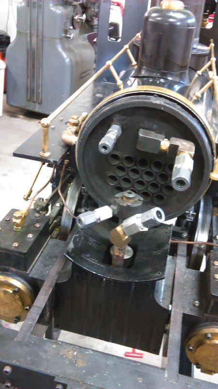
Using various fittings I came up with this:

large.jpg


Seems to fit with no issue, although an elbow at the blower nozzle might be good too.
 
I found and ordered a quantity of SS hex nipples on Amazon that can replace the brass ones used in the prior photo. No luck looking for a 45 degree with mail and female like the brass one. I think I can make one with 2 female threads and use a nipple for the male end. OTOH that 45 degree brass nipple is quite thick, and even if it were to corrode it should be easy to remove/replace.

I am reluctant to modify the SS compression fittings at this time, as they are $20 each. The steam supply setup seems pretty good as it needs only a short curved piece of tube. The blower side is more awkward, but there is plenty of room forward in the smokebox to make a fairly wide curve. I'm not going to finalize it until everything else is set, including the valve piping from the turret.

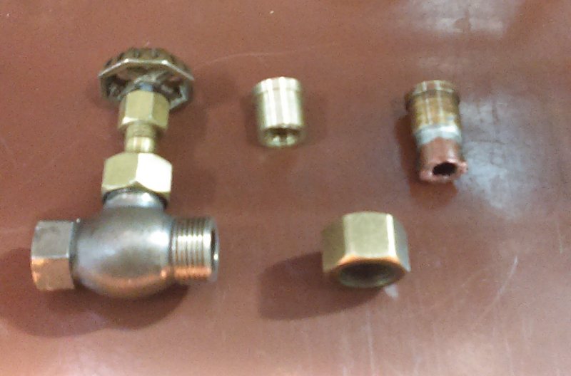
Speaking of which I'm wanting to use brass pipe for the blower valve connection vs. the copper tube I had before, which I felt was unsightly. The valve (I believe it is from Locoparts) has a female thread on one side and a male solder connection on the other. To use threaded pipe on both sides I needed to duplicate the tube end piece that had been soldered on previously. Fairly easy lathe job starting with some 7/16 brass rod.
large.jpg


Spent the rest of the afternoon setting up the CNC mill to thread the many pieces of 5/16 brass pipe that will be needed. First attempts will be hooking up the blower valve and the whistle.
 
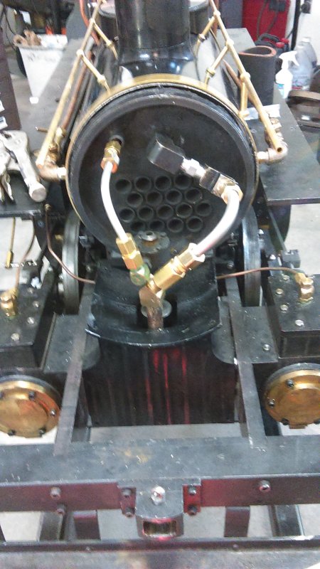
After much fiddling plus discussion with a very experienced builder, I decided to use brass compression fittings along with the SS tube.

large.jpg


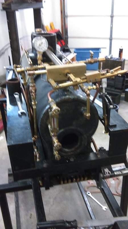
Tube bends were relatively straightforward, and there's no interference with the petticoat. Then I have basically finished up the redo of the piping. Other than the turret being replaced, I redid the connections for the blower, whistle, and water glass.

large.jpg


A few minor tasks left before next attempted steam up.
 
Love your build! I just read the entire thread from the first page, I was hooked couldnt stop reading and looking at the pictures. You have a incredible amount of work into that loco and should be very proud. Nice!
 
Short update: last week I took it to the track for a hydro test on the boiler, which passed. However, several pipe joints had seeps and need to be tightened.

This week I returned to the track and attempted a steam up. Still some small seeps, but I had problems in firing. First issue is that my stack blower is to fast, pulling so much air that the fire gets blown out. Since I don't have a speed control I restricted the flow by blocking the best part of the output. Got it heated uop with the needle off the peg, but couldn't get is past 20 psi. Adding some more coal put the fire out!

Post-mortem is that I likely had too much coal, as it wants a thin bed on the grates. I found some unburned wood I'd supposedly added to help start the blaze.

I'll try it again soon.
 
Hello,

could you be so kind to supply me with the PRR-font? I am using Mach3 to control my home converted super X3 cnc mill.
Best regards
georgjorge
 
Kvom, I know this thread is dead, but I'd like to sincerely thank you for documenting your A3 build! It was an great inspiration for me to begin my own A3 in 1.5" scale back in 2017. I read through the entire thread one day in high school after I bought Kozo's book, and watched years of your work come together in a few hours.

I started with no machining experience at all, and working on-and-off over three years in other people's shops I've completed the tender and locomotive frames, fire grate (first thing I built), tender wheels/axles, suspension and axle boxes, and just today the journal boxes for the tender. Usually I'll work on it for a few months, get sick of it, then come back to the project. Just how my mind works I guess, but I'm entirely committed to finishing it one day! I don't have the luxury of CNC, but I've referred to your thread a few times for guidance.

If you see this, did you ever complete your locomotive? I'd love to see some pictures!

-William Liebbe
Houston, Texas
 
I sort of finished it (no headlight) but decided actually running it isn't my thing. It's been sitting in the vault at the track for three years. I probably ought to try to sell it to someone who would run it.
 

Latest posts

Back
Top