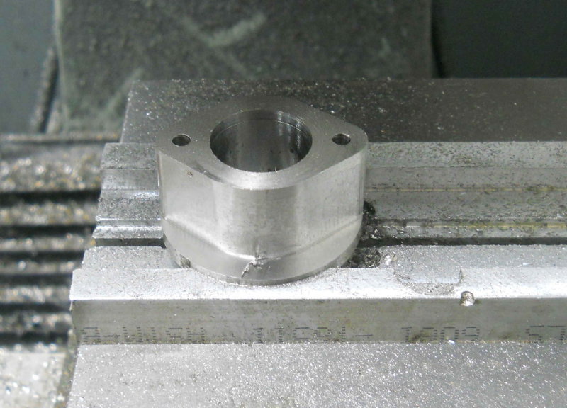
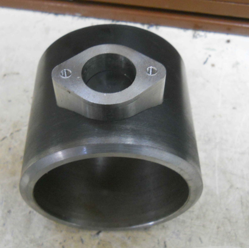
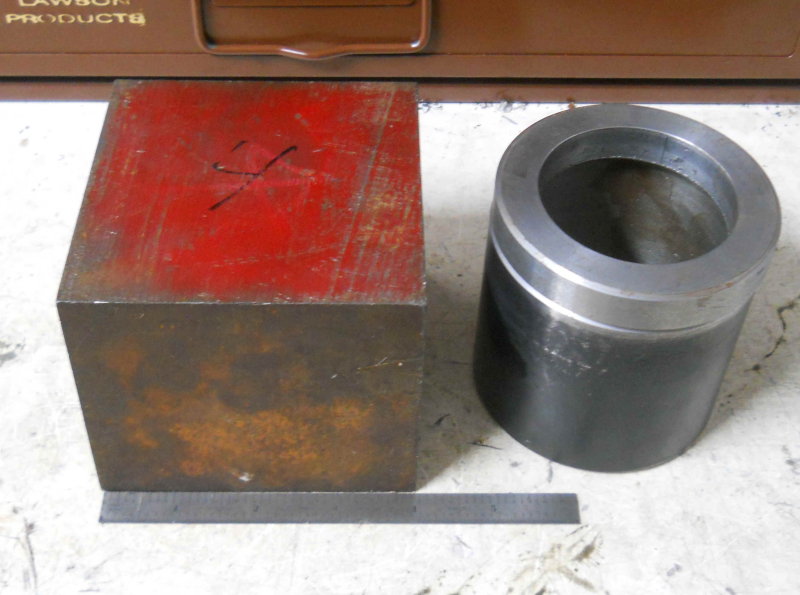
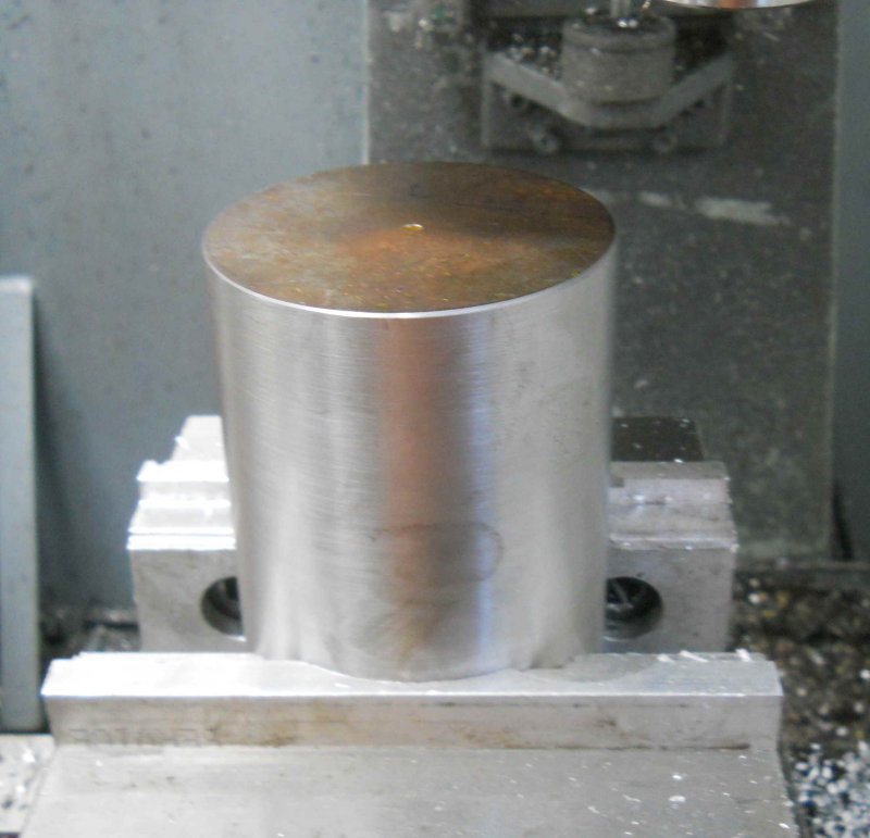
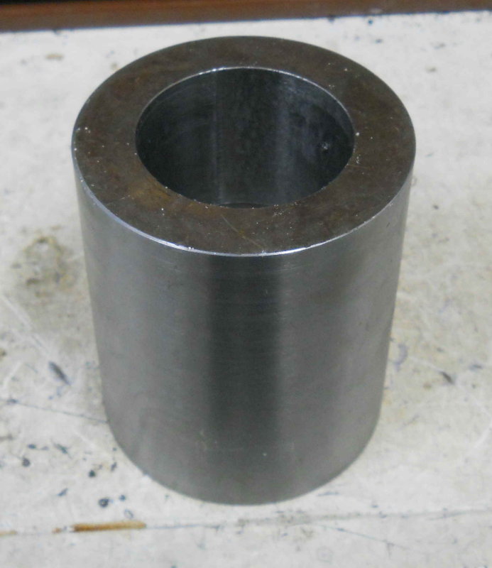
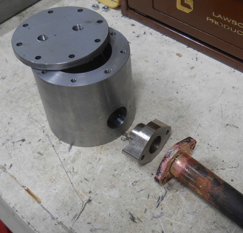
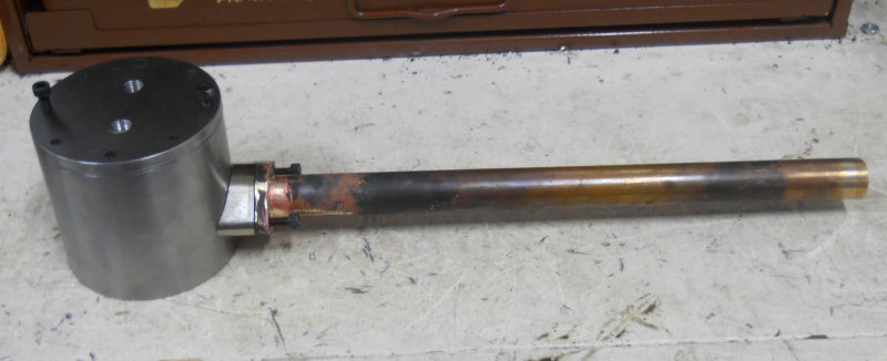
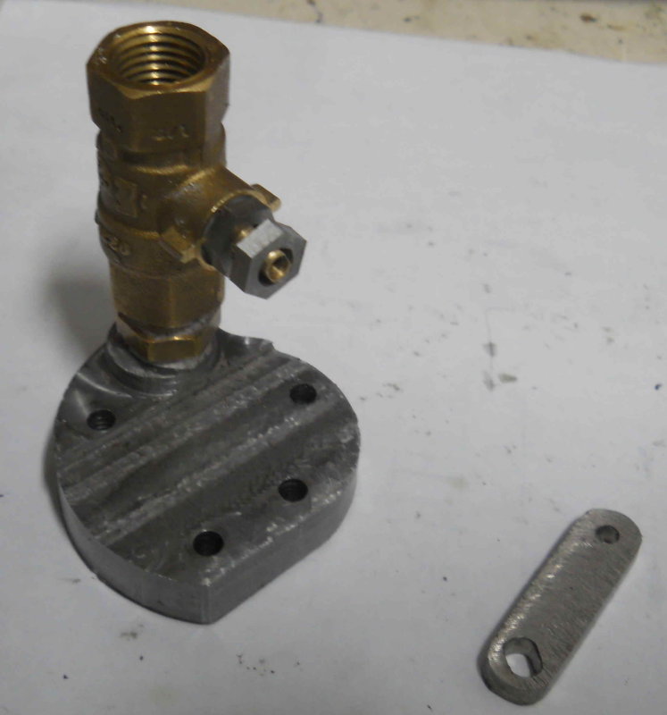
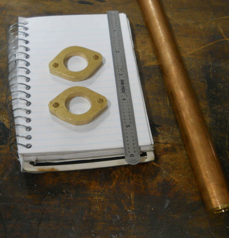
After some more discussion on the steam dome with an experienced builder, I started on fabricating the "can" components that will be welded to the boiler. The first issue was that the flange I had originally was too thin. The tapped holds that secure the cover should not be through into the steam. Therefore I turned the flange off the can leaving a simple cylinder 3.375" OD with a 1/4" wall. Now I need a ring that will be welded to the can to form a 1/2" thick flange 1/2" wide, meaning that the OD will be 2.375".
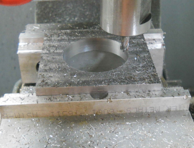
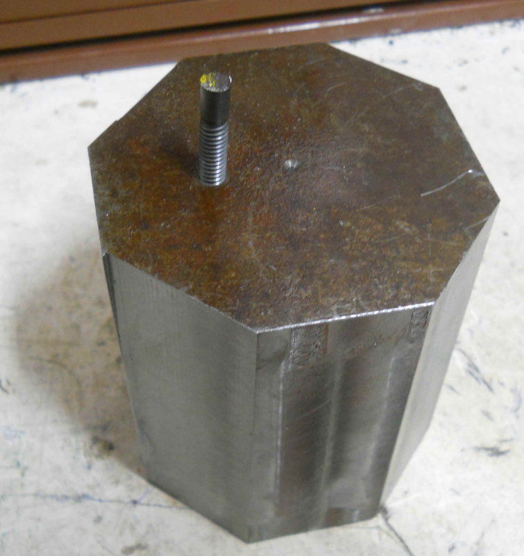
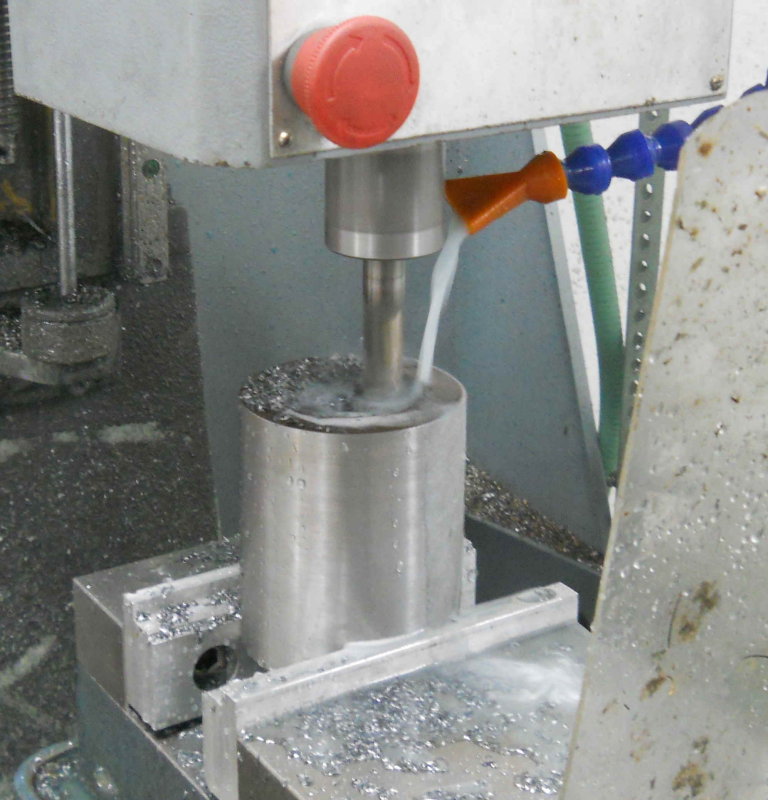
I started with a piece of 5/8" thick HRS about 4" square, faced both faces with a facemill on the manual mill, and milled two of the sides square. Now I could mount the stock on the CNC mill to remove the center material. For this, I wanted to try something new to me. My CAM program allows me to easily draw a flat spiral with any given distance between the loops. So using a 5/16 endmill and a .03" spacing (9% engagement), I would be able to mill at full depth using just the side flutes. This is a type of "high speed machining'. To start, I used a 3/8" endmill to spiral drill a .6" diameter center hole, and then the spiral. A finish circular path brought the hole to its desired diameter.
Total machine cycle time was about 15 minutes.
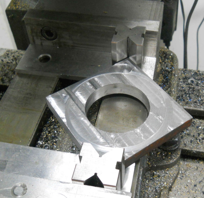
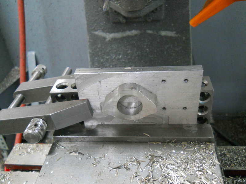
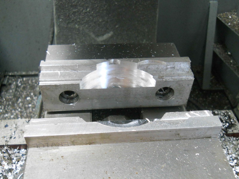
For the OD, I could have programmed a profile cut in CNC, but a large endmill would have cut into the vise soft jaws, and a smaller endmill would have meant a slot depth greater than the tool diameter. So I decided to use the lathe. First I needed to round the corners as much as possible with the manual mill. Here's the setup for the first pass:
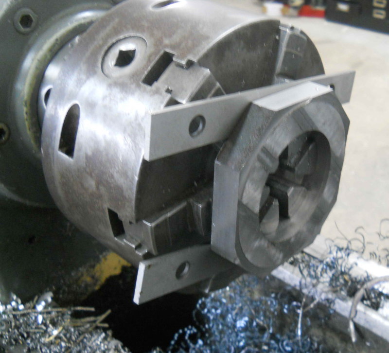
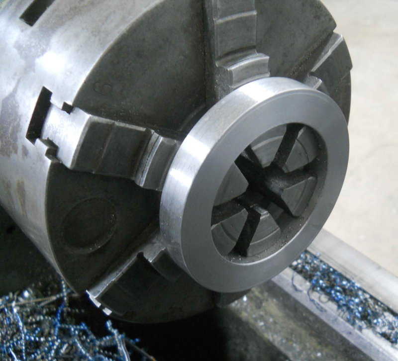
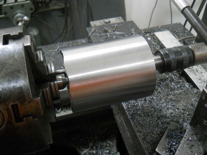
After trimming 4 corners I mounted the work on the lathe as shown here. I used a pair of 1/8" parallels to space it away from the jaws to avoid cutting them.
Then I turned it to slightly larger than final dimension, faced both sides, and chamfered one outer edge to allow a space for welding filler.
The cover mounting holes will be drilled and tapped after welding an cleanup.




![Learning AutoCAD Civil 3D 2014 [Online Code]](https://m.media-amazon.com/images/I/51F3yi9fokL._SL500_.jpg)


![DreamPlan Home Design and Landscaping Software Free for Windows [PC Download]](https://m.media-amazon.com/images/I/51kvZH2dVLL._SL500_.jpg)


