John Deere Engine

Home Model Engine Machinist Forum

Help Support Home Model Engine Machinist Forum:

This site may earn a commission from merchant affiliate links, including eBay, Amazon, and others.
Dave,

Hopefully you'll agree "Better late than never"! Here are some drawings of the head on my last JD Engine. The 3d view only shows one side. The other side is a mirror image.

3D_Heads.png


Drawing:

HeadDrawings.png


These things are hard to visualize and even harder to draw. By the way, My engine uses a 3/16" ball bearing for the slave valve. It also only has 1 hole into the cylinder, not 2.

I'll draw up the valve assembly next, although you can probably imagine how it works.

Chuck
 
I have some additional info on one of the tractors in your videos. The bottom one is a Sampson Sieve Grip. That one is a single cylinder version, they also made a 4 cylinder a little later on. That old boy driving the tractor (Bill), his dad bought it new and they farmed with it around Chico, CA. Bill now is in his 90s and needs a little help starting it, but once its going he is off. He has sold the tractor to my good buddy Buzz Stetler. The agreement is that Buzz bought it but Bill keeps it until he dies or is tired of playing with it. If Buzz dies first, Bill keeps the tractor and the money. Bill didnt tell Buzz til after the deal went down that his parents both lived til over 100. We had a good laugh over that one.

Im not a John Deere expert, but I thought the early ones had the crank throws at 90 degrees? I know the Rumely's are 180 apart, have worked on a few of them.
 
te_gui said:
I have some additional info on one of the tractors in your videos. The bottom one is a Sampson Sieve Grip. That one is a single cylinder version, they also made a 4 cylinder a little later on. That old boy driving the tractor (Bill), his dad bought it new and they farmed with it around Chico, CA. Bill now is in his 90s and needs a little help starting it, but once its going he is off. He has sold the tractor to my good buddy Buzz Stetler. The agreement is that Buzz bought it but Bill keeps it until he dies or is tired of playing with it. If Buzz dies first, Bill keeps the tractor and the money. Bill didnt tell Buzz til after the deal went down that his parents both lived til over 100. We had a good laugh over that one.

Im not a John Deere expert, but I thought the early ones had the crank throws at 90 degrees? I know the Rumely's are 180 apart, have worked on a few of them.

Thanks for that information on the Sampson Sieve Grip. I hadn't been able to find any other information on it. Now that you tell me it's a single cylinder, it's more obvkous by listening to the video again. Neat old tractor!

The John Deere is indeed 180 degrees apart, just like the Rumely and the Waterloo Boy's. Sure wish I had the space (and the extra money) for an old John Deere D. Love those old tractors.

Chuck
 
I finally finished my copy of "Chuck Fellows John Deere". I am really tickled with it and love the John Deere sound. It actually sounds better in the shop than on the video. I am using a little Sony digital camera and the sounds distorts somewhat.

I want to thank Chuck for the photos and sketches.


Dang! Looks and sounds real good. Did you put an air balancing control between the two cylinders?

Chuck
 
Congrats putputman. Nice job!
 
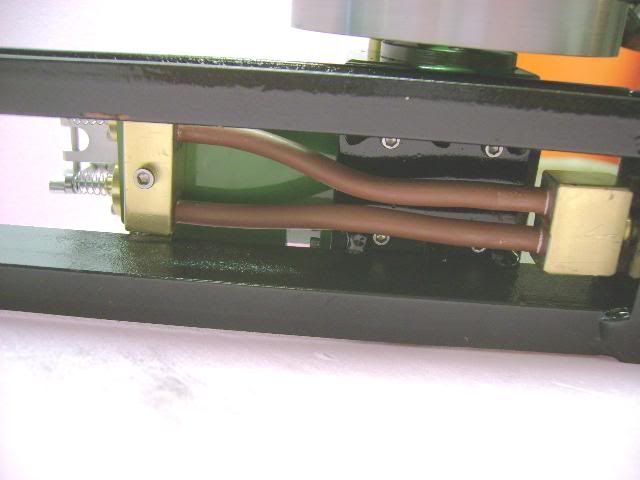
Chuck, I thought I would try a large air supply right up to the valves, so I run two 1/4 copper tubes on the bottom. It seems to work OK.

DSC01432.jpg
 
Fantastic. :bow: :bow: :bow:

Love the sound - If the video is distorted it must be really great in the flesh.

Best Regards
Bob
 
Chuck, I'm very interested in your engine. Enough so that I'm trying to draw up a set of plans so that I can try to build one. I'm confused about the valve operation. On page 1 you posted drawings of your valve system. On page 3 you show pictures of the overhead valve assembly. I can't seem to make sense of how it works....I understand the drawings, but the pictures seem to show something completely different?

Charlie
 
Charlie, you are right, in the end, I didn't use the valves in the drawings, but rather defaulted to my previously used poppet valves.

I've got some other pictures and drawings I can scare up.

Chuck
 
Here is a drawing of the valve assembly. Two of these required.

JDValve_Assembly.png
 
This is a picture of the head from the top. The valve assemblies fit into the two large holes. The hole in the side of the valve assemblies matches up with the interference holes from the exhaust holes, which you can see coming out the side of the picture.


Head 012.jpg


ValveAssembly5.jpg


ValveAssembly4.jpg
 
Here are pictures of the head from the bottom (cylinder) side. The holes in the face of the head lead from the cylinder into the exhaust holes.
Refer to the drawings in Reply #80 of this thread for some drawings of the head only.

I'll try to get some detail drawings of the head and the valve operation in the next couple of days.

Chuck

Head 013.jpg
 
OK, Here's the drawings of the head:

JDHead.png
 
OK, now I see! That poppet valve works exactly backwards to the way that I was thinking. A ball bearing and spring fit into the exhaust passage, right.

Charlie
 
cfellows said:
I'm going to try something different on the cam gears to avoid a big cam gear. I'm going to use a double reduction gear set, the first being 3:4 ratio and the second being 2:3 for an overall ratio of 1:2.
Chuck

Chuck, looking at the gears, it seems that as long as the pinon gear and the cam gear have a ratio of 1:2 it doesn't matter how many teeth the middle gear has...it's just an idler. I'm looking for the best source of gears. SDP has the right gears, but the prices aren't so nice.

I milled the crankcase from a solid block of aluminum this weekend. It looked like an aluminum snow storm in the shop! I then made the camshaft. I machined each cam separately and soldered them to a 1/8" drill rod shaft. How much lift did you build into your cams? I've got .090" now, but the cam profile looks wrong. The angle of the cam against the pushrod looks too steep. I've either got to make the cam diameter larger or lower the lift.

Charlie
 
Charlie,

You're right, the number of teeth on the idler gear is irrelevant. I used 24 pitch, 9 tooth pinion wire for the primary gear which I bought from SDP. This is a 12" length of pinion gear with no center hole. You cut of the length you need and bore your own center hole. I cut mine long, then turned down a shoulder for a set screw. The cam gear is an 18 tooth which I made myself.

A lift of .090" is about right. The rise, dwell, and fall aren't critical, although faster is better. Did you make lifters for the push rods to sit in? The lifters, as I recall, are 3/8" (maybe 5/16") diameter where they contact the cam and are shouldered down to 3/16" where they pass through the guides in the crankcase.

Let me know if that doesn't answer your questions... (lookin forward to pictures!)

Chuck
 
Back
Top