Jim builds his second v-8

Home Model Engine Machinist Forum

Help Support Home Model Engine Machinist Forum:

This site may earn a commission from merchant affiliate links, including eBay, Amazon, and others.
Alexandre Machado said:
Okay Jim!

I understand... What's the computer program that you use for this? Is not a common CAD program, correct ?

Jeff, thank you too! I found the informations.

Alexandre

Alexandre, I don't know what Jim is using but take a look at Geardxf. I have found it very useful - good free program: http://www.forestmoon.com/Software/GearDXF/.

Jim, just out of interest what drives are you using for your mill currently? Mine's been running for 6+ years on Gecko G201s so I certainly would recommend Geckos, they are great.
 
LongRat said:
Alexandre, I don't know what Jim is using but take a look at Geardxf. I have found it very useful - good free program: http://www.forestmoon.com/Software/GearDXF/.

Lots of programs generate gear profiles. Autocad Inventor will do it, SolidWorks too, and Mastercam. Google Gearotic Motion. It's demo version is free.

Jim, just out of interest what drives are you using for your mill currently? Mine's been running for 6+ years on Gecko G201s so I certainly would recommend Geckos, they are great.

I've got an old Camtronics servo drive circa 1999. It was built before Gecko was invented. Camtronics is still around, they're a good outfit with which to do business and this drive works well. There current drives use Geckos. I would like to go to Gecko drives for only one reason. When I power this drive up the motors glitch a few thousands of an inch. Therefore, if I'm in the middle of a project I generally leave the drive on if I have to leave or else I have to be careful to leave a datum point I can get back to. I understand Geckos don't do that. Anyway, I've got lots of ways to spend a thousand dollars and a new servo drive at this moment is not on the top of the list .
 
The G201 stepper drives I use do that jumping - it is because the motors mechanically drop into the closest step when you power them down, and if the 'on' command requires them to go to a microstep position you will jump to it. If you power down on a full step you don't get this - but you never know if you are on a step or not so it doesn't help. You would either have to have repeatable home switches or re-reference against your vice/part etc. probably as you currently are doing.
Having said that I am not sure if the servo drives behave the same way. The latest G320X is awesome and only $121 each if you can re-use you existing power supplies that is not an expensive option.
 
LongRat said:
Having said that I am not sure if the servo drives behave the same way. The latest G320X is awesome and only $121 each if you can re-use you existing power supplies that is not an expensive option.

Good point. If I made changes I change out the motors to 1100 oz-in servo motors. They're available for a couple of hundred each. I currently have 600 oz-in Aztec (spelling) motors. I'd change the drivers to Gecko's latest servo driver with a 90 volt power supply. I'd be a happy man. I'd like faster rapids cuz currently I only get about 25 in/min on the x and y and 9 on z. That being said, the BP will do a lot of nice work. For example, I circular interpolated the holes for the v8 cylinders and they're round as being reamed.
 
Last edited:
I've been busy but not in the shop. I finally got back to it. I made a couple of helical spiral gears to drive the distributor and decided I needed to test them out. I made a setup to run them for a while. I ran them for an hour without any noticeable wear. This setup also gave me an opportunity to measure the center to center distance.
DSC02232.jpg
 
Before I could drill the block for the distributor I had to lay out its position in the cad program. I could now do that because I now know the spacing required for the gears. Here's a picture of the layout.
DSC02234.jpg
 
You know, they run well but don't look all that good. I know a guy who has a gear reduced servo motor laying around so today I ask him if I could use it. He gave it to me. I'm gonna set it up on a fourth axis with it. I only have three outputs but I think I can use y output for driving A. I can't think of a need for y when I'm cutting gears. All I'll need is x, z and the rotational axis, I think. Maybe I can make some better looking ones.
 
So I drilled the block for the distributor. It's 15 degrees off of vertical.
DSC02236.jpg

I made a distributor shaft and stuck it in the hole.
DSC02246.jpg
 
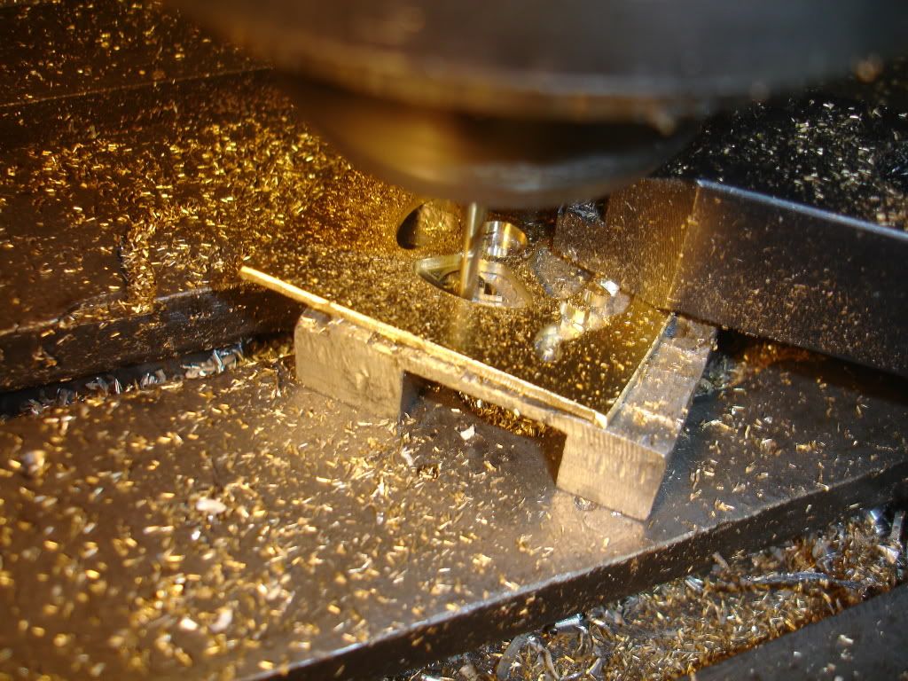
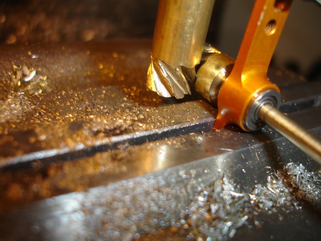
Next project, make some timing gears. Here I'm cutting spokes in 1/16 brass sheet. Look closely you'll see teeth cut on the right side near the clamp. I cut one side, then reclamp and cut the other. I bore the center hole in the same setup so I don't loose my center. Having the center in the center is pretty important when making gears.
DSC02248.jpg


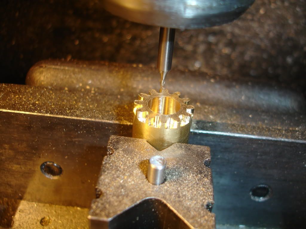
A fellow need a pinion too.

DSC02250.jpg


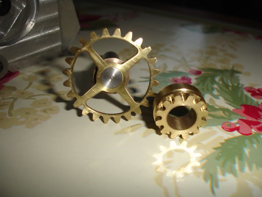
so here's they are, all ready to be installed.

DSC02253.jpg
 
The engine is looking great, can't wait to see and heard it run. Your work is really awesome.
 
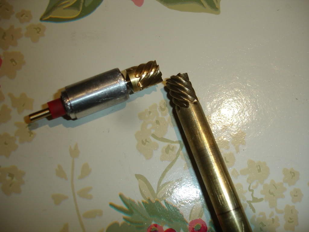
Although the helical distributor drive gears worked ok I wasn't pleased with the looks. Today I made a new pair. One is the real deal. The second is only for a test pinion. The real one will have to be cut in the camshaft. I haven't yet cut the cam to length so I'll have to wait to cut that gear. Here's a picture of the finished pair. they work really well. When installed in the block they turn really smoothly.
DSC02263.jpg
 
I don't own a rotary table but I do have a spare gear drive servo motor. I machined a coupler to attach the 3/8 stock to the end of this motor. The coupler is seen in the movie. I made a support to hold the stock near the end being machined, also obvious in the movie. I programmed the a axis drive motor so a distance of 1 gave me exactly 1 rovolution. I wrote a program that plunged the z then advanced the x axis .5 inches while rotating the A axis 1/2 turn. That math returned a 45 degree helix, just what I wanted. I took three passes for each of the 8 teeth. First pass was 0.020 deep, second pass was 0.060 and a final pass 0.081 deep. The final depth came from a gear formula book, the same place from where the tooth form came. Well anyway, here's a movie of it all happening.
 
I'm finally getting back to the project. Gonna start off with a question: How much space do I need between the cylinder and block wall for a water jacket? I have only 0.032 space between the cylinder wall and the block. Is this enough or do I need to find more? I know water can flow through that area but the block won't hold much volume. And too, how far down in the block should the water jacket go below the cylinder top? The motor has 3/4 dia pistons and 3/4 stroke. Any information about this subject would be appreciated.
 
Jpeter, I was just looking at the pic of the timing gears being milled---What size endmill was Used?
Thanks John
 
jpeter said:
I'm finally getting back to the project. Gonna start off with a question: How much space do I need between the cylinder and block wall for a water jacket? I have only 0.032 space between the cylinder wall and the block. Is this enough or do I need to find more? I know water can flow through that area but the block won't hold much volume. And too, how far down in the block should the water jacket go below the cylinder top? The motor has 3/4 dia pistons and 3/4 stroke. Any information about this subject would be appreciated.

My water jackets are .100 larger so .050 all the way around. The jacket starts .250 down and is .500 tall. If you want to look at the drawing I will have the full set there Wednesday.

If you need more room you could always go with a smaller bore and then groove the outside of the liner.


jpeter said:
I'm finally getting back to the project. Gonna start off with a question: How much space do I need between the cylinder and block wall for a water jacket? I have only 0.032 space between the cylinder wall and the block. Is this enough or do I need to find more? I know water can flow through that area but the block won't hold much volume.

I would think along the lines of how much water can you ultimately move, then figgure out how much space is needed to not impede the flow.

And too, how far down in the block should the water jacket go below the cylinder top? The motor has 3/4 dia pistons and 3/4 stroke. Any information about this subject would be appreciated.

Full size practice of late only keeps water around the top 25% or so of the cylinder for iron liners in a aluminum block. At our scales, we need all that just for head bolt thread engagement. I would jacket the rest as deep as I dared, but most of the convection will be from liner--deck--coolant rather then liner--coolant.
 

Latest posts

Back
Top