James Coombes but not as you know him

Home Model Engine Machinist Forum

Help Support Home Model Engine Machinist Forum:

This site may earn a commission from merchant affiliate links, including eBay, Amazon, and others.

Jasonb

Project of the Month Winner!!!
Project of the Month Winner
Joined
Mar 30, 2008
Messages
4,178
Reaction score
1,590
Location
Surrey, UK
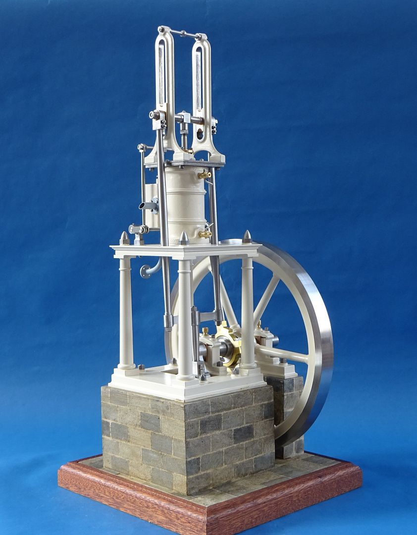
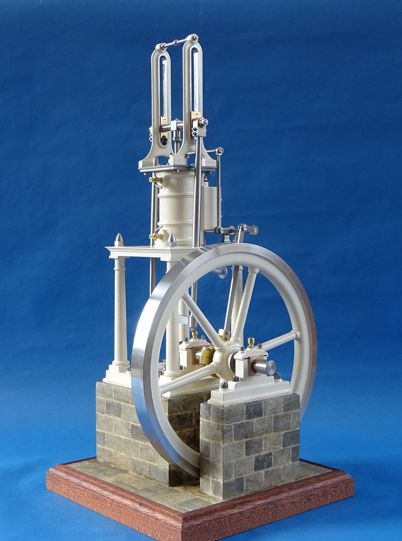
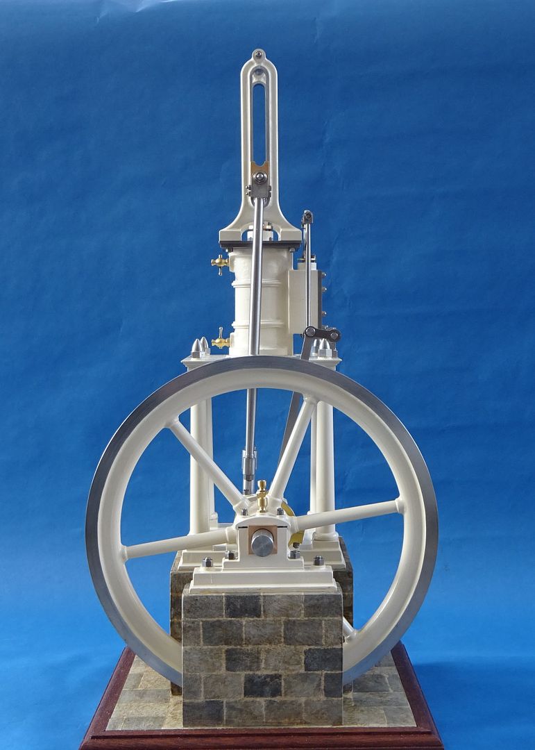
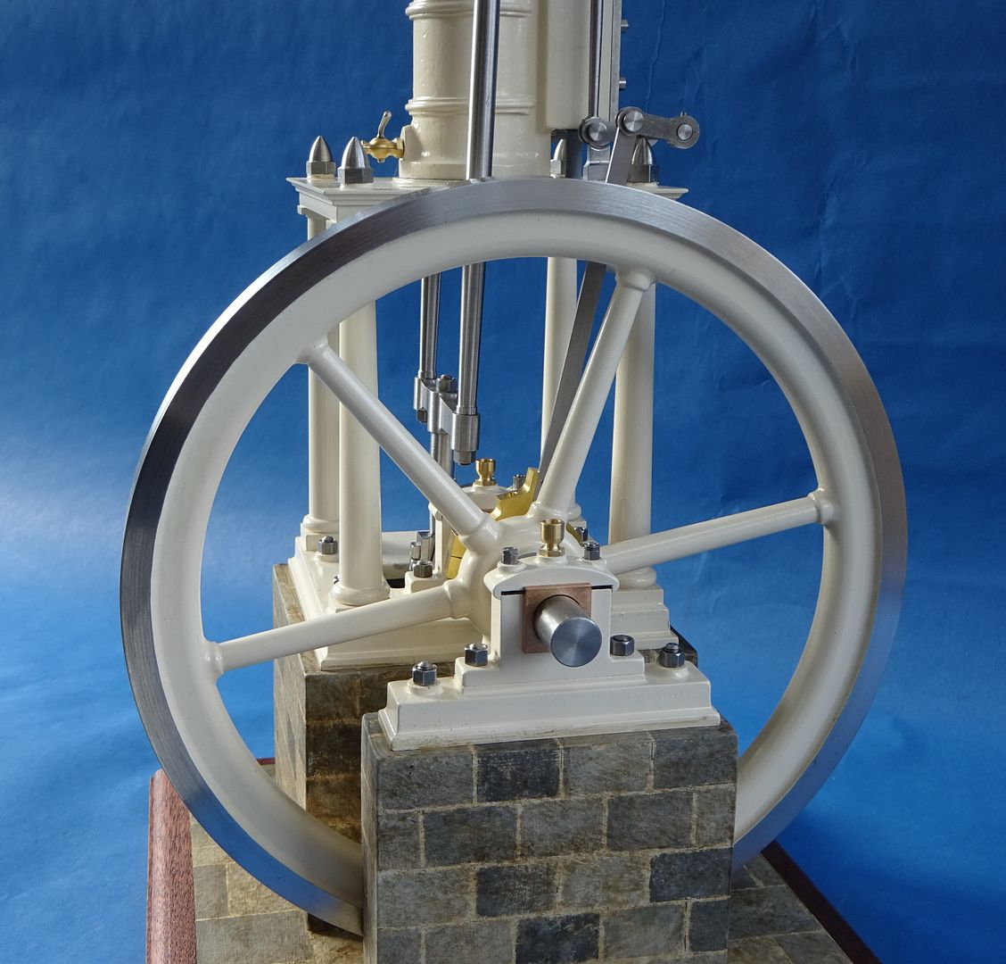
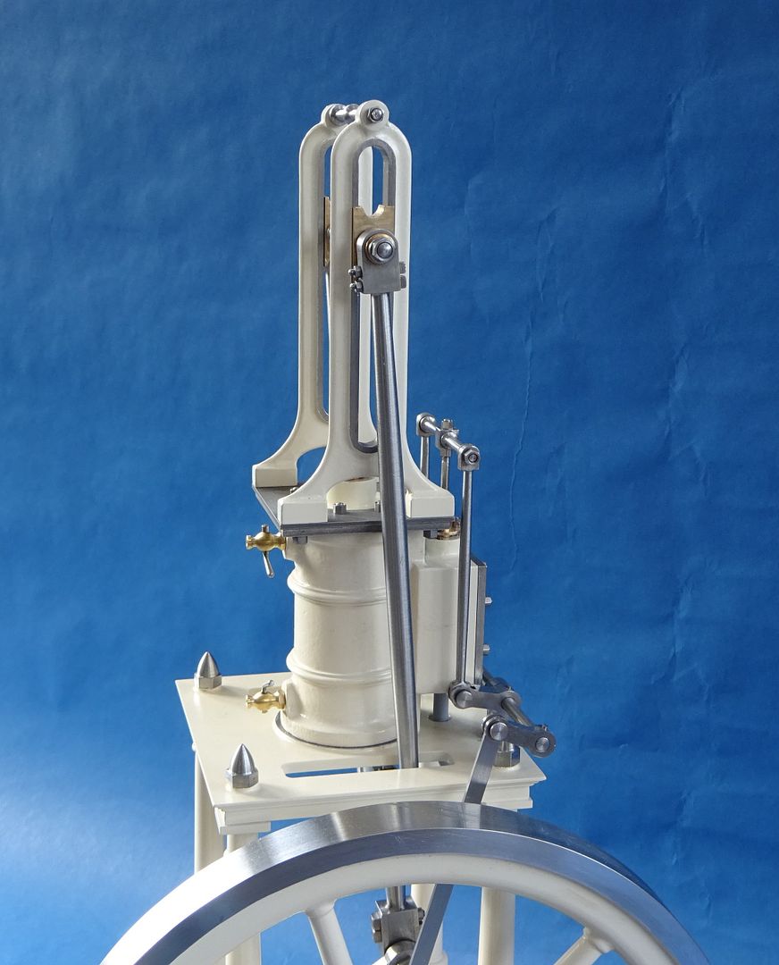
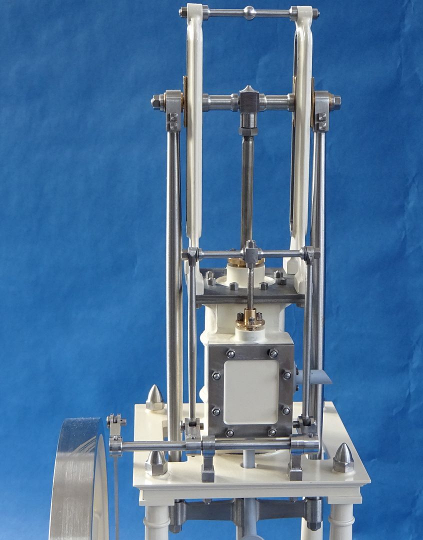
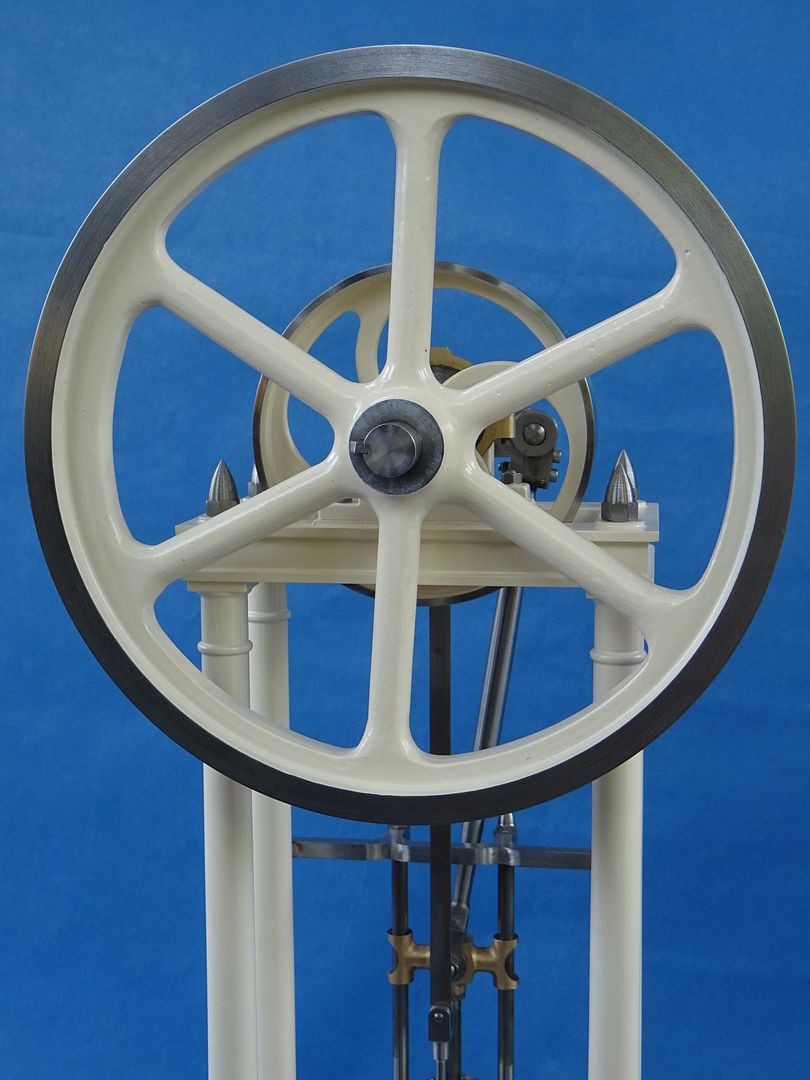
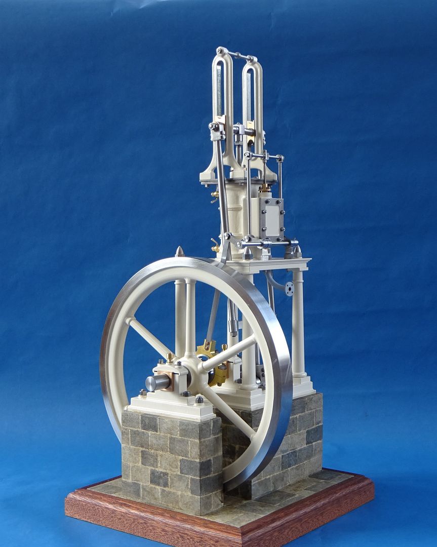
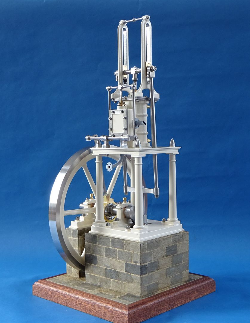
This is my recently completed version of the Stuart James Coombes, I just used a Stuart Cylinder casting and fabricated or cut the rest from solid and it was at least twice the fun for half the price. I went with the same Ford Ivory that I used on the Real and painted a stone effect onto the base. Quite pleased with how it turned out and I'm glad I went with the different flywheel as the larger size and lighter spokes seem to suit the look.
DSC04633.JPG


DSC04636.JPG


DSC04638.JPG


DSC04640.JPG


DSC04632.JPG


DSC04641.JPG


DSC04642.JPG


DSC04643.JPG


And finally a video of it running on about 5psi of air

 
Great workman ship and beautiful finished model.
Gail
 
Fantastic workmanship.

JasonB continues to stet the bar very high.

Superb masonry work too !
The masonry on the floor is the cat's meow.

And good portraits like that are difficult to take, at least that has been my experience.

Another great Jason B engine.
Congrats !

.
 
That's definitely a work of art. Nice machined details and finished off with a good paint job and just a little bling. It runs so quietly and smoothly. I can easily imagine a large version running a factory or something.

Thank You for posting.

--ShopShoe
 
There was an era when the old engines were definitely works of art, reflecting old gothic architecture, like these.

Functionality and elegance.


STEAM-BOAT-PACIFIC.jpg


8709502821_8cb7abd12d_z.jpg


condenser a1.JPG
 
Last edited:
  • Like
Reactions: Zeb
Unfortunately, mine never look like works of art... more like functioning scrap! But beauty is in the eye of the beholder.
I too love to behold beautifully finished engines, and Jason, you have done that! Well done!
But, please forgive me for this observation (I cannot criticise such workmanship). It appears that the crank and piston mass has not been balanced on the flywheel? Perhaps this is to preserve the aesthetics of the model? Personally, I attempt to balance the mass that accelerates the motion when the piston is descending, so the slow-motion view can show the upward stroke at the same speed as the downward stroke. I can only guess that James Coombes and his equals may have done the same? As these engine were really used to power machinery, the finished product (often fabric, but also metal products) could sometimes how any "hunting" of the speed, so they were balanced to give as constant an engine speed as possible. Often modellers miss the opportunity of refining the motion to look real, yet the Victorian machine makers and their modellers would have done so. (My Great Grandfather had models of his products - Mine pumping engines, coal drops and coal wagons - that were used as sales examples as he touted his wares to the various mine owners.... who rarely could read drawings, etc. So my Grandfather insisted I make things work properly!).
But well done on a beautifully presented James Coombes engine!
K2
 
Yes it is a problem that afflicts many models that are run for display as the slow speed combined with no actual load on the engine which means that gravity tends to come into the equation. I have found it worse on grasshopper engines where the weight of the beam has to be lifted and then wants to drop and the more recipricating mass there is in any vertical engine the more the issue .

If you just rest your finger on the flywheel to apply a slight load it goes away and as our forefathers tended to use their engines to do work adding balance may not be true to the original and has a detrimental effect when you run the engine faster. So it is a toss up whether to balance things up or not. It is possible to remove metal and fill with something lighter to keep the "look" correct but that is OK if only running slowly.

I did do it on the previous much modified Stuart which was based on the "Real" and used the Stuart 7" flywheel casting rather than this larger fabricated one. it did smooth things out a tick over but could only be run upto a certain speed before it slowly walked across the bench. You can see at the 9 o'clock position that the rim has been thickened by bonding on two layers of Code 4 lead with JBWeld and then blending in with body filler

DSC04582.JPG


Slowest running at the end of the video


Again at the end of this video you can see the grasshopper is affected but as it was a scale model of an actual engine with mor edetail added than the published design I built it as it was when intended to work.

 
Wow Jason,
that is inspiring workmanship. Do you use BA threads? The hex nut to stud proportions look really neat. Did you make the acorn/domed nuts also? Did you make a form tool? Are they SS?
Again, super nice work
 
I rarely use BA these days, the whole engine including threads and fixings was redrawn in Metric.

I don't use "standard" metric nuts these are ones sold for Model Engineering and are typically one size smaller hex and of a taller style.

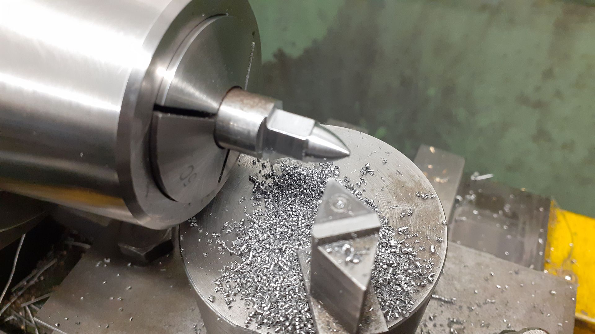
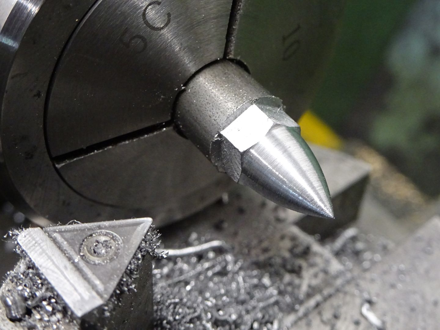
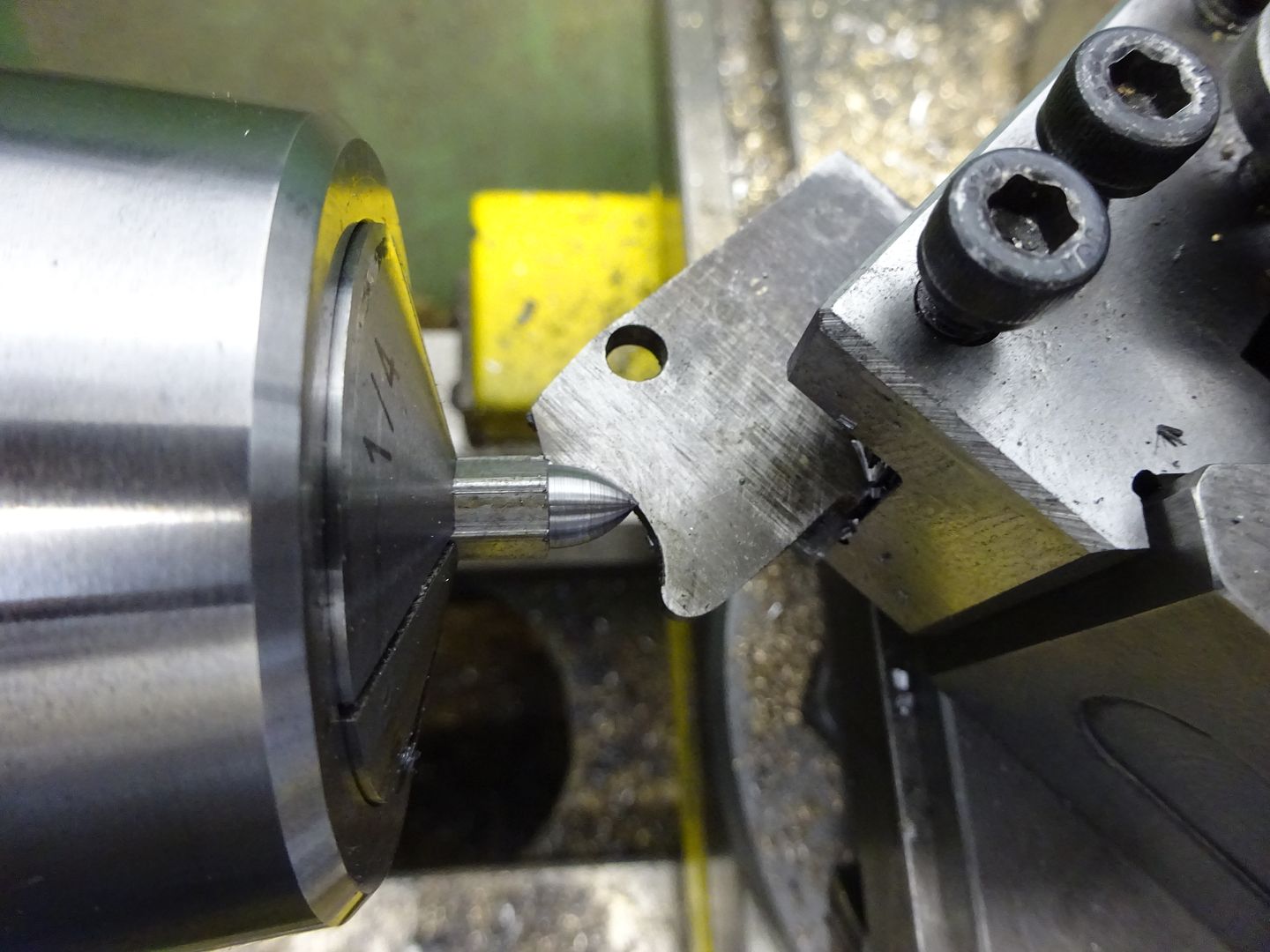
Acorn nuts are a free cutting mild steel, I did them with a ball turner, the triangular insert gives a nice chamfer to the top of the hex at the same time but have used a form tool in the past (repurposed from something else in photo)

20221204_143309.jpg


DSC04488.JPG


DSC01263_zpsjrnfnmri.jpg
 
Curiously, when making 8BA studs in brass for a model, the parting tool gave me a sort-of ball shape on the end of the stud. The shape is developed by the chjip-breaking centre groove in the parting tool, and treat way that the brass stud naturally broke from the parent metal. On a set of studs it gives a sort-of artistic feature when the Nuts are in place. Again, I buy nuts that are 8BA thread but 9BA hex for the spanner.
The history of reducing flat dimensions for nuts really comes from material improvements over the decades.
Whitworth standardised things, suitable for the lower grade steels (20 ton) available in his lifetime. BSF threads (or so I was taught) became possible when better steels (40 ton) became cost effective, and higher stud tensions were practical, but requiring less outside metal for the nut/spanner. This became a huge cost saving in industry but if you are making a 19th c design, BA are about the correct ratio of size, wheras on a 20th c design, reduced BA hex sizes are closer to scale ratios.
But "Modeller's eye" prefers little stuff, as many commerccial designs are made with larger than scale fixings anyway.
At least, that is what I was taught....
I like the pictures of ball turning, etc.
K2
 

Latest posts

Back
Top