I need suggestions. Lathe

Home Model Engine Machinist Forum

Help Support Home Model Engine Machinist Forum:

This site may earn a commission from merchant affiliate links, including eBay, Amazon, and others.
Joined
Dec 29, 2016
Messages
2,354
Reaction score
1,621
Location
Viet Nam
Hi All !
I need suggestions.
In the process of using the new lathe, there are a few ideas I want to add to the lathe
This is one of those ideas
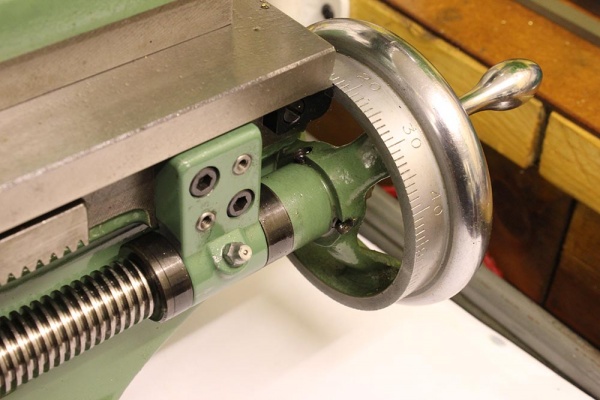
- Moving the tool table with small distances like 0.3 0.5 ...mm is really difficult to be precise with rack and pinion

20240324_B.jpg


I don't want to change the existing lead screw because I also need it during machining. So I want to add another set of lead screws as shown in the picture. Of course, when installing a new lead screw, it requires a mechanical or electrical mechanism, then I can only choose 1 of the 2 lead screws. : I can do that

20240326_A.jpg


I need suggestions.
What thread pitch should I choose for lead screws?
And do you have any other ideas?
Thank you !
 
Other Ideas??

In studying various lathes and watching different people address the problems of exact positioning that you want to address, I can offer what seem to be the traditional ways of working toward precision.

1. Install a DRO and try for the best adjustment and calibration so you get the best repeatable results when machining.

2. Use a dial (or digital) indicator to measure the travel of the saddle relative to the lathe bed. The original purpose-made device for this was called the "TravaDial" (spelling unknown). I set up a dial indicator to do this from time to time and prefer the dial indicator because I can more easily watch the pointer move to the point I want to stop.

3. Make a carriage stop so you can move the saddle only to a preset position where it will stop every time on the limit where you set the preset.

4. On related, but different, operations you can also have a carriage lock so the carriage will stay in one place while you use the cross-slide and compound travels to adjust the cutter location.

5. I have seen tool holders that mount on a QCTP where the final tool travel is adjustable with an actual micrometer head.

--

RE: more precision leadscrew travel and repeatability:

1. Study and investigate sources of backlash. Check rack precision and the rack gear precision and fit.

2. Investigate the half nuts and the half nut engagement mechanism to see if there is room for improvement: This is a major source of problems on my 7x mini lathe. I have rebuilt and modified that system on my lathe several times.

3. There is a possibility that the leadscrew geartrain also has a substantial amount of backlash. Perhaps there are adjustments to be made or perhaps someone sells higher-precision gears you could install.

I'm sure others will chime in on this.

--ShopShoe
 
Hi All !
I need suggestions.
In the process of using the new lathe, there are a few ideas I want to add to the lathe
This is one of those ideas
- Moving the tool table with small distances like 0.3 0.5 ...mm is really difficult to be precise with rack and pinion

View attachment 154891

I don't want to change the existing lead screw because I also need it during machining. So I want to add another set of lead screws as shown in the picture. Of course, when installing a new lead screw, it requires a mechanical or electrical mechanism, then I can only choose 1 of the 2 lead screws. : I can do that

View attachment 154892

I need suggestions.
What thread pitch should I choose for lead screws?
And do you have any other ideas?
Thank you !
Corner is better they last longer.
Looks like mini lathe in photo.

Now they both inch and metric.
Need to chose if like threading tpi or mm.

My lathe has 2mm pitch so all my projects use 2mm or 1mm so do not need a threading dial.

The question about use dial indicator most time. If longer I have portable DRO for that day. I have use more one as most shops do not dro on the lathes and is handy on some work.

Dave
 
Set the top slide parallel to the lathe axis and use that to put on fine cuts or space out things like cylinder cooling fins. It's what I do

If you really want a leadscrew then extend what you have and mount a scale and handwheel to the right of the existing leadscrew bracket. In use simply engage the half nuts and turn the leadscrew with the handwheel. This is what Myford lathes have and also my old Emco.

HK1470.jpg


The existing rack arrangement can be made easier by fitting a larger handwheel and also a larger graduated dial. The ideal is to fit a geared handwheel so one turn moves the dial a specific amount such as 1mm or 0.100"
 
I would go for a dial indicator holder and a Micrometerscrew for a stop. On the tool grinder works gerat and is cheap.
Then you can try if adjusting with the hand wheel and rack pinion is really that difficult. (using above suggestions) I have a DRO on the Lathe and fine adjustment is a matter of "bumping and carefully moving the hand wheel" (could be improved, but most of the time the z-travel is not as critical. To hit 0.1 mm on the DRO is not a problem, 0.01 mm would be fiddly, but rarely necessary.
On some machine I saw a planetary gear in the hand wheel, which makes a more easy fine feed. (Jasonb wrote same)
Would a worm gear to move the hand wheel be an option? (similar to Thomas universal dividing head)
Depends were you put the 2nd lead screw, will it be difficult to reach?

Greetings Timo
 
Last edited:
Depends were you put the 2nd lead screw, will it be difficult to reach?

Greetings Timo
That's the problem, I'm thinking
But after seeing picture of @Jasonb
I have a new idea: maybe I will do the same and it will have a mechanical part so I can separate the lead screw from the gearbox when I turn the lead screw with the hand wheel.
Perhaps due to my habits and experience, I like to move the carriage with lead screws
Thanks for the comments 👍.
 
If you really want a leadscrew then extend what you have and mount a scale and handwheel to the right of the existing leadscrew bracket. In use simply engage the half nuts and turn the leadscrew with the handwheel. This is what Myford lathes have and also my old Emco.

HK1470.jpg


The existing rack arrangement can be made easier by fitting a larger handwheel and also a larger graduated dial. The ideal is to fit a geared handwheel so one turn moves the dial a specific amount such as 1mm or 0.100"
👍👍👍👍.
 
You find the DRO is easier to install and use.
You install on backside so out of way too.

Using the lead screws has it problems that most do not like back lash and needing to disconnect the feed.

Dave
 
Last edited:
Set the top slide parallel to the lathe axis and use that to put on fine cuts or space out things like cylinder cooling fins. It's what I do

If you really want a leadscrew then extend what you have and mount a scale and handwheel to the right of the existing leadscrew bracket. In use simply engage the half nuts and turn the leadscrew with the handwheel. This is what Myford lathes have and also my old Emco.


The existing rack arrangement can be made easier by fitting a larger handwheel and also a larger graduated dial. The ideal is to fit a geared handwheel so one turn moves the dial a specific amount such as 1mm or 0.100"

Adding a handled wheel to a powered lead screw does require that you check that nothing is fouling the handle before you engage and threading or powered feed activity. Sort of obvious, but I ended up taking the handles off a small CNC machine as they were more of a hassle / danger to fingers than the value of moving an axis by hand. Some machines that offer powered and manual operation have fold flat handles on the hand wheels.

I've seen some hand wheels for the tail stock end of the lathe lead screw that mount on a hex or other form of extension so they can be removed unless you need them. As already said by others, see what if anything you can do to reduce the lost motion in the rack and pinion, and then consider either stops or dial indicators. Either option is a lot easier and will give good return for the time spent. A set of feeler gauges in a stack that folds open like a pocket knife makes it easy to set the distance between the cross slide and the stop, beats trying to get the tips of a set of calipers into such an awkward space. I like the kind sold for setting valves, they have a bend at the ends. You can add up the leaves needed for the dimension and press the ends closed readily even if you have skipped a number of the middle leaves.
 
...I ended up taking the handles off a small CNC machine as they were more of a hassle / danger to fingers than the value of moving an axis by hand.

Rapid travel on a CNC machine will spin the handwheel at approximately what rpm?

Cutting the coarsest possible thread that the lathe's gearbox provides at a sensible spindle speed would spin the leadscrew at approximately what rpm?

It would be good to supply these numbers, so we can assess the real world severity of the problem you highlight with a mill handwheel when the logic is applied to a lathe.

The lost motion statement is a bit of a red herring. How often do you need to move the carriage both back and forth a precise distance for the same cut? Backlash is not a probem so long as you take it up consistently.

His problem is that the rack and pinion is coarse pitch and the handwheel is small diameter. The combination of these two make precise control difficult. You could have a zero backlash rack of the same pitch and using the same handwheel, the problem would not change.

---

Out of field idea 1: 3D print an epicyclic reduction gearbox to go between the carriage handwheel and rack pinion. That would give the fine control required.

Out of field idea 2: double the diameter of the carriage handwheel and the same circumferential movement results in half the linear carriage movement compared to using the standard handwheel.
 
His problem is that the rack and pinion is coarse pitch and the handwheel is small diameter. The combination of these two make precise control difficult. You could have a zero backlash rack of the same pitch and using the same handwheel, the problem would not change.

---

Out of field idea 1: 3D print an epicyclic reduction gearbox to go between the carriage handwheel and rack pinion. That would give the fine control required.
That's the problem I'm having
The way to solve the problem is also quite good
-----
Thanks for all the comments!
Edit /
I have adjusted everything with this lathe : it's fine .
I can use rack and pinion, I just want to improve the lathe a little to control the movement better, that makes machining a little more comfortable
 
Last edited:
Those are the same as I suggested, the bigger handwheel and graduated dial or the geared dial both commonly seen on the popular Myford lathe so beloved by model engineers.

One turn of the carriage handwheel moves my carriage 1.2" with the divisions being 0.1" which is no good for fine movements but a combination of gearing and a larger scale diameter could easily make those divisions 0.001". But I can't be as88d to do it and just use the top/compound set parallel to the lathe axis

If you ever want to do any milling on the lathe then the leadscrew handwheel is the way to go both to put on a cut and to feed just like you would the x axis on a mill.

I do quite often thread on the lathe at 500rpm so handwheel on the end would be going at 166rpm which can be a bit fast if it were to hit you, certainly would not want it with the mill when cutting at 500mm/min feed which would put the handle at 250rpm
 
Rapid travel on a CNC machine will spin the handwheel at approximately what rpm?

Cutting the coarsest possible thread that the lathe's gearbox provides at a sensible spindle speed would spin the leadscrew at approximately what rpm?

It would be good to supply these numbers, so we can assess the real world severity of the problem you highlight with a mill handwheel when the logic is applied to a lathe.

The lost motion statement is a bit of a red herring. How often do you need to move the carriage both back and forth a precise distance for the same cut? Backlash is not a probem so long as you take it up consistently.

His problem is that the rack and pinion is coarse pitch and the handwheel is small diameter. The combination of these two make precise control difficult. You could have a zero backlash rack of the same pitch and using the same handwheel, the problem would not change.

---

Out of field idea 1: 3D print an epicyclic reduction gearbox to go between the carriage handwheel and rack pinion. That would give the fine control required.

Out of field idea 2: double the diameter of the carriage handwheel and the same circumferential movement results in half the linear carriage movement compared to using the standard handwheel.
A cnc handwheel could easily be spinning at 500 to 1000 RPM based on 100 IPM feed rates and a 5 to 10 TPI leadscrew, triple that for 300 IPM rapids. On something like a Sherline, with 20 TPI screws, a 60 IPM feed will be doing 1200 RPM. That's about the top end for rapids or feeds on this machine though, you are getting towards the upper range of stepper capabilities and not many machines this small get built with true servos.

A lathe threading 8 TPI at 240 RPM spindle speed would only revolve at 30 RPM assuming an 8 TPI lead screw. It won't stop just because something gets caught up in it though until the caught thing or a part on the lathe breaks or fails. Hopefully a shear pin or some other low cost item to repair, and hopefully not a body part that was caught. Problem is when you put a wrench down in the wrong place, or put something down at the far end of the lathe "for just a minute", and then start up working at the head stock end of the machine. Air hoses and cords to lights or Dremel style tools and such are notorious for getting snagged. The longer the lathe the easier it is to lose sight of the far end in the midst of other stuff.

Lost motion isn't an issue if you maintain a constant force, but in intermittent cuts it adds to play and vibration in the system. No idea why that's a red herring, no intentions to mislead or deceive anyone. Slop in machines always has some negative impact, although the OP says he has resolved this issue so it isn't of concern any more.

His (The OP's) problem isn't a small hand wheel, it is NO hand wheel. If he had a hand wheel and could use the lead screw for fine manual feed the rack and pinion wouldn't even be coming to this party, his needs could have been resolved with a mag base like a Mighty Mag and a dial indicator. JasonB posted the Myford lathe with hand wheel picture.

The original posters picture does however show a hex on the outboard end of the tail stock lead screw support, I'd be thinking about that as a good location for a removable hand wheel provided the hex can be secured so that it won't loosen or tighten to bind the lead screw in use.
 
That's the problem I'm having
The way to solve the problem is also quite good
-----
Thanks for all the comments!
Edit /
I have adjusted everything with this lathe : it's fine .
I can use rack and pinion, I just want to improve the lathe a little to control the movement better, that makes machining a little more comfortable
I can see that.

l am uses to very large lathes and they have sloop in hand wheel to rack.

Dave
 
Hi All !
And this is the result - can it be temporary or permanent !!??
With a little change, 14mm Hexagon bolt
I drilled a 13mm hole and then milled with a 2mm milling bit, a little bit of filing and the result was a tight fit.
Of course I had to turn off the automatic running function of the sliding table, after all I rarely use it. If I need to use it, I only need a few minutes to adjust

20240725_112050.jpg
20240725_112122.jpg
20240725_112303.jpg
 

Latest posts

Back
Top