How to mill an elyptical shape?

Home Model Engine Machinist Forum

Help Support Home Model Engine Machinist Forum:

This site may earn a commission from merchant affiliate links, including eBay, Amazon, and others.

IgorW

Junior Member
Joined
Oct 30, 2012
Messages
11
Reaction score
21
Hello!

How would you attempt to mill an elyptical 'hole' without a CNC? I know the 'pantograph' or 'copy' method. I'm interested in milling this shape using a conventional mill. Also the question is not limited to a milling machine. Maybe there is a different way?
Any ideas are welcome!

Cheers from Poland!
 
Set your material up on an angle to the bed and plunge cut with a large endmill . That will give an elliptical hole.
 
Thanks for your input :)

Thats not what i mean, an endmill will leave a round hole, just where it makes contact with the surface will be elyptical . I'm after something like the 'cylinder case' in a Wankel engine but instead of the 'double-bubble' shape I want it to be elyptical. By the way - how is a Wankel 'cylinder case' made without CNC? I remember that this shape can be achieved by a geometric operation where a circle is revolving around or inside another .
 
What Brian suggested can be turned inside out and cut a solid ellipse that looks like a slice of salami. Mount a slanted plate on a RT and pretend to cut a circle. Another way to look at... an elliptical plug would fall off the elliptical hole cut with Brian method but with a small end mill all around.
 
I'm remembering the Wankel engine. I didn't think it was truly elliptical, but I had to do a bit of googling to find a video to confirm what I thought. Check out the shape in this animation. I'm going to go out on a limb here and say that there is no way to replicate that shape with a manual milling machine.--Brian
 
https://en.wikipedia.org/wiki/Trammel_of_Archimedes

Trammel of Archimedes

Would that do you any good? Not sure how you would adapt that to a mill.
I'd consider this as a way to make a pattern in a softer material like lexan or maybe even aluminum with hand tools. Then use the pattern in tracer mode on the mill.

Back in my younger years I got to work on a "mill" left over from WW2 production that was a manual tracer mill. It might have been a Pratt & Whitney but in any event it had dual milling heads and a steel pin that was used to trace around a pattern. I could see it working great for external forms. However the mill did have a drive system for the axis that was rack and pinion which I suspect gives a lot better feed back than a lead screw to the operator.

About the only other thing I can offer up here is to use sound lay out techniques to get close with the ellipse on the mill. Then you finish up with a German milling machine (file).
 
Epitrochoid is the shape of the chamber in a rotary engine, iirc Mazda spent a lot of money developing the grinding machine to grind this shape . Dunno how you would machine that on a manual machine
 
Draw it out in CAD and produce a set of co-ordinates then use the handwheels and DRO to move to each co-ordinate and make a plunge cut. Closer you set the step over the smoother the result but takes longer, largest dia cutter that will fit in the hole will also help.
 
The probale difficulty is the incorrect spelling which should be 'Elliptical'

There is such a thing as an elliptical chuck which has certainly been available to ornamental turners since the early 1900's, The Tsar of Russia had a a Holzapffel(Sp?) lathe. Surprisingly, Holzapffel's books are still available free on the internet.

I have no doubt that Tubal Cain( T.D. Walshaw) would mention one in his Ornamental Turning book.

Worth a Google again but with the corrected spelling?

Does this help?

Norman
 
I asked Joe Pieczynski on YoyTube the same. He replied, but didn't have a solution. If it was a matter of setup we probably would known about it by now.
Think we are looking at a hefty attachment..
I would like to make a beam for a steam beam engine.
Rudy
 
Hello Wizard69,

The Vertical-Miller-Profiler seems to be a "copy" machine. A simple pantograph can be used instead.
 
Draw it out in CAD and produce a set of co-ordinates then use the handwheels and DRO to move to each co-ordinate and make a plunge cut. Closer you set the step over the smoother the result but takes longer, largest dia cutter that will fit in the hole will also help.

While googling for a pantograph I found this on YouTube. It Shows a software based DRO with pantograph feature. Shapes can be copied from a drawing. While milling, the tool Position is shown on the drawing so that the shapes can be approximated easily. The coordinate plunge cut method can be performed much faster because the tool Position is shown in on the drawing while moving the axes.
 
Last edited:
  • Like
Reactions: JRR
I've always thought an ellipse could be drawn using two nails, a rather slack piece of string tied to each nail pounded into a board and putting a pencil inside the string and running it around. With this in mind, I always wanted to make an elliptical pool table. A dot at one nail mark and a pocket at the other nail mark. Any ball rolling over the dot (with no spin) would always rebound off the cushion into the hole.
 
David is correct on the geometry. Years ago I wrote a routine for LinuxCNC's NCGUI plug in that generates true ellipses and milled inside or outside the profile with the endmill chosen by the operator. It used ellipse formulas that were directly derived from the "two post" method generation.

(Doesn't help for a manual operation, but I remember people on the LinuxCNC forum trying to figure out how to make a true ellipse as well.)

...Ved

Precisely. That's the reason I gave an approximation method that uses circular arcs and can be machined with the use of a rotary table.
 
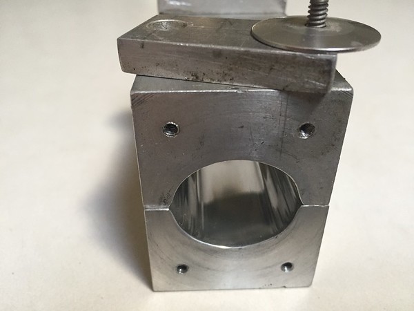
I used the technique that Brian mentioned, to mill an elliptical laser cavity. I made many cavities in this way. The largest used a 2" end mill and was about 6" long. This was a double ellipse, where the foci of each ellipse intersected in the center. This was to be used with 2 flash lamps to focus onto a laser rod. The others used a 1" end mill for single ellipse cavities of about 3" long. Here's a photo of one I have remaining.


I angled the mill head to match the aspect ratio of the ellipse that I wanted to machine. As the bit traverses through the material, it cuts an elliptical path.

Eric
 
Wow! I didn't expect so many replies. Thanks to everyone! I should have specified what I'm looking for in the first post. What I need is something similar to a Wankel rotor case - it has to be very smooth on the inside just like in a Wankel engine. Thats because I would like to try to build an experimental engine around it. An ellipse (thanks for the spell check ;) )
is defined by semi major and semi minor axes. I need ~20 percent difference between those two. Lets say 1" and 1.20". At this size the thickness of the case would be around half inch. What comes to my mind is similar to the method Brian Rupnow suggested. The work is mounted in the vise on tall parallels leaving some space underneath. The work is NOT slanted, its parallel to the table /bed. First drill a hole slightly smaller then the 'minor diameter' of the ellipse .The head of the mill is set at an angle (out of tram). I'm guessing 10-15 degrees - more angle means more difference between the axes of the ellipse but there is a limit to that. Now with a flycutter on a long shank plunge cut creates an elliptical hole. The space underneath the work is to clear the tool from hitting anything. Also the more angle on the mill head creates a risk of the shank hitting the work. If the parallels aren't high enough there is a risk of hitting the vise before the plunge cut is finished. I think a simple drawing will be made to proof my idea. For now I have to help preparing the easter breakfast. So thanks again for all the ideas and happy easter to everyone!
 

Latest posts

Back
Top