How to ? Hall effect

Home Model Engine Machinist Forum

Help Support Home Model Engine Machinist Forum:

This site may earn a commission from merchant affiliate links, including eBay, Amazon, and others.

ozzie46

Well-Known Member
Joined
Dec 12, 2008
Messages
1,325
Reaction score
103
I have my electrical parts for my Hall Effect ignition. Now I need advice on how to set it up.

I have been searching youtube and the web for mounting setups and such but can't find much except for demos on how the mag effects the sensor

I plan on mounting the hall sensor on the side of the distributor in a window type opening, but how to hold it?

# 1 Mount it with a bit of silicone as a vibration dampener or just hard mount it? I've read where heat is bad for it.

# 2 Use 4 mags ( it's a 4 cyl ) or use 1 mag and a "bottle cap" shutter? What is a bottle cap shutter and what does it look like?

# 3 How much air gap between sensor and mag?

# 4 Where's the best place to put the circuit board?

I'll probably have more questions later.

All help greatly appreciated.

Ron
 
do you have pictures of some parts you are using ??
there is many ways to kill a cat:(
 
In automotive practice they are usually encapsulated in plastic, I just superglued mine in place.

Here is a pic of a bottle cap type shutter, the vanes fly between the magnet and the sensor, switching the magnetic field on and off. I consider it safer then flying magnets.
shapeimage_2.png


Gap will depend on how powerful a magnet and how sensitive the sensor. You can also use steel or iron to increase or channel the magnetic force where it works best.
Put the circuit board in a well grounded location as far as possible from the ignition wires, same goes for everything attached to it.
 
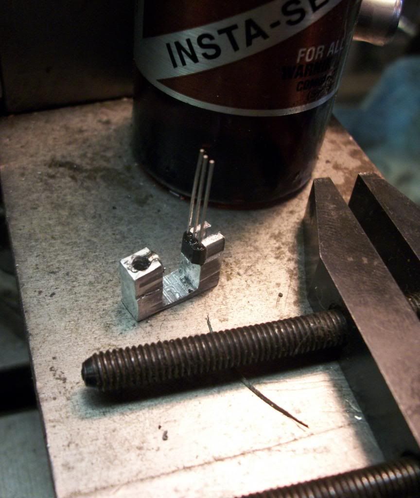
Here is a pic of a complete hall and magnet assembly on a steel U frame to concentrate the tiny (1/8x1/16) magnets lines of force across the sensor. It triggers whenever metal crosses in between the sensor and magnet. Two threaded holes in the bottom are 4-40. That was one I just hacked together real quick, sorry its so crude, plenty of room for improvement there. It fires off a crankshaft disc with a notch cut in it.
100_0920.jpg
 
Hi Luc, I'll try to get some pics today or tomorrow. My son has to come over to help me build the circuits. But I can get pics of the points casing I'll be using.

Thanks Lakc. That gives some reference to go from. Don't apologize, for the sample. It shows me a direction to go. Many thanks.

Ron
 
Hi Ron,
Here's how I mounted the Hall sensor on my 4 cylinder engine. The piece of aluminum has 2 ears where the 0-80 screws go through. On this piece of aluminum is also a small channel that holds the Hall in place. This fits into a window in the side of the distributor. I use super glue to hold it in place although I have been told this isn't a good way to do it. Apparently when the super glue sets it puts a stress on the Hall but I have never had a problem. I am attaching a photo and a copy of the distributor drawing for my 4 cylinder engine.
gbritnell

4 cyl distributor.jpg


View attachment 4 CYL OHV SHT P.pdf
 
I mount my sensors to the bottom of the distributor with a drop of super glue. Just mill a small slot in the side, slip it in , and glue it down.

I shoot for .050 air gap between the sensor and the magnets.

I use 1 magnet per cylinder in a disk in the bottom of the distributor. It's the "flying magnet" setup

I put my electronics in the display base and bring the sensor wire, ground, and high voltage wire up from the board.


You can see in this picture the sensor wire coming out of the distributor and going into the base. There is the
same setup on the other side for the high voltage going to the distributor. I don't like bringing the high volt
and sensor wire up the same place. I like to keep them as far apart as reasonable.

Done4.jpg~original
 
Thanks for the pic and plan George, it's starting to make sense now.

Steve I'm glad you brought up keeping those wires apart and that base looks great.

Luc, here's the pics I promised.


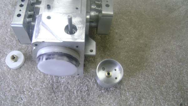
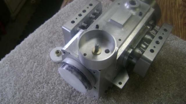
I have a germ of a plan developing. Here goes.The round thing is what was the points canister which will now hold the magnet and shutter assembly. I will probably use silicone to mount the sensor in the side of the canister and put a cover over it like George did.

The shaft sticking up is what was to drive the cam for the points and I will use it for the shutter thingy. I'll mount the magnet in a ally piece and screw it to the floor of the canister and use the air gap Steve suggested. Man that shutter thing is going to be pretty thin.


Son was over and I was missing a couple of components. He picked them up at
Radio Shack and will be back tomorrow to fix up the board.


I think this might work.

Ron
 
Hi Ron,
I use super glue to hold it in place although I have been told this isn't a good way to do it. Apparently when the super glue sets it puts a stress on the Hall but I have never had a problem.

I guess thats possible, but the real stress is making a dovetail cutter that small. ;)

I have a whole strip of surface mount hall sensors. Next version should have the magnet behind the sensor and metal collecting and moving the magnetic field in front of it like the newest sensors. For that, I will try and make a run of sensors in an epoxy molded form.
 
Back
Top