How do I model a supercharger rotor?

Home Model Engine Machinist Forum

Help Support Home Model Engine Machinist Forum:

This site may earn a commission from merchant affiliate links, including eBay, Amazon, and others.

aonemarine

Well-Known Member
Joined
Nov 18, 2012
Messages
887
Reaction score
212
Tring to figure out how to model the hypocycloidal and epicycloidal curves of a supercharger rotor in alibre cad. This is really making me pull my hair out!
Steve H, have you managed this with your model blower??
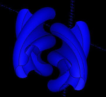
Im trying to design a 3 lobe rotor for a blower with a 71ish cid displacement...
 
Several different ways.
Here are the basic equations.

Roots blower impeller is combination of Hypocycloid and Epicycloid curves
switching from one to the other whenever they touch.

a is equal to large circle radius and b equal to small circle radius
Origin is center of large circle. t is the radial angle.
These are for 2 loves. I have the equations for other lobe patterns but not handy right now.
Gearotic will also generate them for CAD input.

Hypocycloid
x = (a - b) cos(t) + b cos((a/b - 1)t), y = (a - b) sin(t) - b sin((a/b - 1)t)

Epicycloid
x = (a + b) cos(t) - b cos((a/b + 1)t), y = (a + b) sin(t) - b sin((a/b + 1)t)

If your modeling program can take parametric inputs then you are home free. If not, dump the equations into a spread sheet and import it something like this and then smooth it. You can set "t" to as fine a resolution as you want.

I can help you set any of it up if you need help.
Gail in NM

Code:
pline
1.0000,0.0000
0.9886,0.0007
0.9551,0.0052
0.9012,0.0173
0.8298,0.0400
0.7444,0.0755
0.6495,0.1250
0.5497,0.1887
0.4495,0.2656
..........
 
Thanks for the input Gail. I think i might be able to bumble through the equation for the 2 lobe rotors, but what about for a 3 lobe rotor? Im no engineer, so this is going to take me some to sort out and understand so forgive the stupid question. The equation is for basically plotting points to create the hypo/epicycloidal arcs and (t) would be the resolution? Ugggg....wish i would have paid more attention in school....

Edit: t= radial angle, i should have read your example more closely...
 
Ok, i think im really screwing this up. Someone check me on this please. On the hypocycloid, A=3 B=2 T=1 i get X=2.9997715414??? Is that right? If it is, what do i need to do to get the next position???
Uggg. My brain aches now....
 
Just out of curiosity, does this require a four or five axis cnc?
 
When I first posted I was on my way out the door and just got back in and have some time to expand a little bit on what I said. A little bit will depend on what tools you have available, both computer and machine tools.

Do you have Excel? If so I will update a spread sheet that I wrote a long time ago to do all the calculations for you. When I wrote it, it was just for my own use so I did not put any notes in it or make it easy to change parameters. Won't take but a little while to clean it up.
Gail in NM
 
Yes, i do have excel. Was my math atleast correct? I enjoy figuring things out in traditional manners, it makes things more clear over the long run.
 
Do you have a pic or sketch with some rough dim's you could post?

John

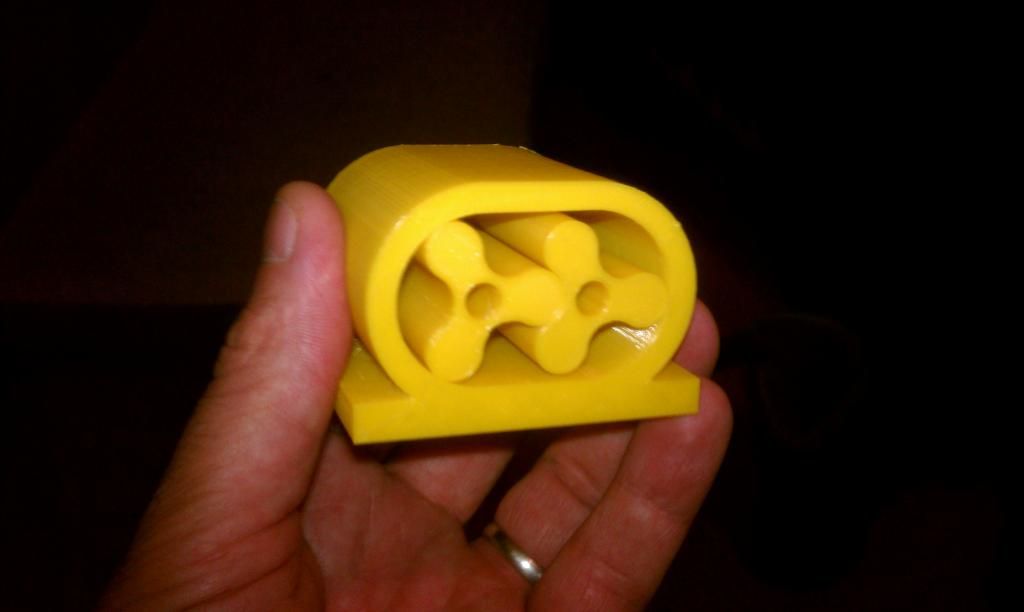
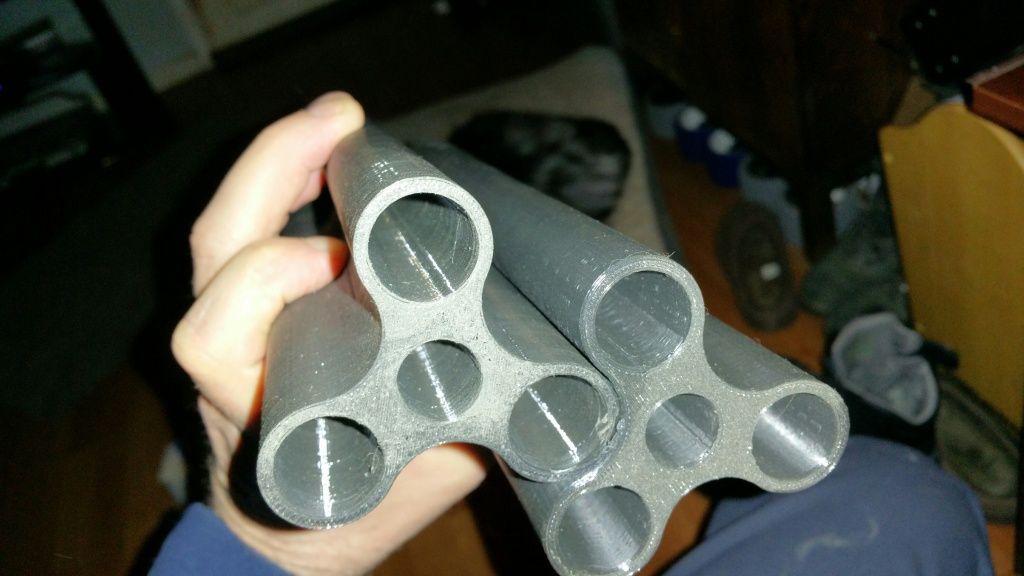
Not yet. I had done some modeling of some rotors before, but the geometry was not correct and any lash in the gears would cause the rotors to collide. The rotors were 3" dia 3 lobe and the lobe ends were .5" radius. With a 10" long rotor the displacement would have been aprox 72 ci. I 3d printed the rotors with the intention of investment casting them. I never cast them.
I can post a pic of them if you would like.?
 
I think you are off. The original equations I gave you have a couple of conditions and I should have mentioned them. My poor memory ne3eded a refresh.

The ratio between the circles must be an integer relationship. That is the large circle divided by the small circle must equal 2,3,4...etc. This ratio determines the number of lobes. Give me about 1/2 an hour and I will update the Excel spread sheet and that will make it easy for you to check your math.

Second item is that the angle in the original equations is in radians so if you are working in degrees they will have to be converted to radians. That is 2Pi radians = 360 degrees. The spread sheet will do the conversions.

Gail in NM
 
well that explains a couple of things. I should have set a=4 and b=1, also explains why t=180 or t=360 both had x=-1 LOL
this was a small test model,

and here were the printed rotors,


sooner or later ill get it sorted out LOL
 
I did this some time ago on BobCad.
Was quite a lengthy task. I did make the rotors on a 4 axis machine, they came out well but have since melted them down for another project. There were 7hrs machining Time in each rotor from 75mm dia billet 7075. Next time I will be casting them allowing for finish machining in order to cut down the operation time.

I have played with Alibre but am not very good with it.

 
Sorry for the delay. I had some power hits that slowed me down.
I have attached the Excel spread sheet. You can play with it to double check your numbers.

I will post a few screen shots of what it looks like imported into Autocad tomorrow evening. Busy day tomorrow during the day.

You can change the number of increments, number of lobes and the large circle radius. The small circle radius is calculated from the large circle radius and number of lobes.

Sheet is set up for a sample with 5 degree increments which is too coarse for machining but it gives you the idea.

Gail in NM

View attachment Roots2.xls
 
I have seen roots type blowers that have "straight rotors". They move air from top to bottom at low pressure.
 
Not sure if this helps any, but this is a helpful link for M62, and M90 Eaton superchargers. It has some dimensions, and twist angles. http://www.3800supercharger.net/

I can's seem to find it, but I know the guy who made that site has also made a cad animation of the basic function of the M62. Not sure if he has an detailed cad on the rotors though. Might be worth sending him an email from the contact info on that site. His name is Bill.

Also, if it would help, I have a couple of each version if you want any dimensions from them. Actually, I have a set of M62 rotors I do not need. You can have them if you pay for shipping.
 
The eatons are an entirely different beast than the roots type superchargers. I really need to stay with the roots type for simplicity. I plan on making a pair of these supechargers for the flathead im building for betsy. Im not sure that twin superchargers of such reduced size is a wise idea, but it would look cool :)
 
I thought they were screw type compressors?? Maybe i need to take a better look at them.
 
Aone: I know that you are beyond this point but since there are quite a few people following this thread I wanted to post a little bit of one way to get from the equations to a drawing of a roots blower rotor or coordinates that can manipulated for machining.

To get to a drawing in Autocad I extract the X and Y coordinate columns for both the hypocycloidal and epicycloidal into two comma delimited files that I can use for script files to generate a polyline for each. The polylines are overlaid on each other and then used to trim each other wherever they cross.

The photo show first the hypocycloidal and then the epicycloidal curves as plotted from the above spreadsheet. Then they are overlaid on each other and trimming begins with the last photo showing the result rotor outline.
Gail in NM

RootsScan0001.jpg


RootsScan0002.jpg


RootsScan0003.jpg


RootsScan0004.jpg


RootsScan0005.jpg
 

Latest posts

Back
Top