Gear formulas question.

Home Model Engine Machinist Forum

Help Support Home Model Engine Machinist Forum:

This site may earn a commission from merchant affiliate links, including eBay, Amazon, and others.
Here is some info for standard pitches I hope you find useful. When making a straight hob you first need to make a 40 degree cutter. The cutter is a mirror image of the tooth you want on the cutter so it is designed to have a flat tip and you measure your depth of cut from that flat. It is somewhat difficult to measure that flat so I did some quick math to find out how much length was being removed. The Width Column is how wide the tip needs to be. The Length Column shows how much length to remove from the 40 degree cutter to get the tip you want.

Alternately, if you know the length of the tip you need to remove you can just increase the depth of your cut by that much. So the Depth Column shows the standard depth of cut and the W/tip Column shows how deep to cut if your cutter is ground to a point and the tip still in place.

Finally, the 20 Degree Column adds a factor for making your cut using your compound set at 20 degrees just as you would do a 29 degree angle for a 60 degree thread cutting tool. So using a factor of 1.06 for a 20 degree angle use this column so you can read the dial on your compound to get the correct depth.

I have only verified the 32 pitch by making actual cuts and checking the results.

Code:
Pitch  Width  Length Depth  W/tip  20 degrees
48   0.015  0.0221 0.0449 0.067  0.07102
32   0.023  0.0336 0.0674 0.101  0.10706
24   0.03  0.0439 0.0899 0.1338 0.141828
20   0.036  0.0526 0.1079 0.1605 0.17013
18   0.04  0.0585 0.1198 0.1783 0.188998
16   0.046  0.0672 0.1348 0.202  0.21412
12   0.061  0.0892 0.1798 0.269  0.28514

 
tornitore45 said:
A real helical hob can not be used on a simple mill.
The gear must be positively driven around as the hob is carving.

Oddly enough, I just finished watching the DVD of Jose Rodriguez do exactly that. He managed it quite easily, while noting that you have to take care on the first round of cutting to allow the hob to seat properly. From there on, the hob cut and drove the emerging worm wheel throughout the process. End product was impressive and appeared to be quite adequate for the average home shop project.

Steve
 
Had to wait for a new end mill to make a new gear cutter. Attached is a picture of the results. The gears are 32 pitch 24 tooth gears. They match up fine with a commercially made 32 pitch gear and the tooth profiles are almost exact. I did end up with a new question about a calculation. I understand the total depth of the tooth, but when you make the cutter it does not cut straight in from the tip because you center a gap in the cutter with the center of the gear blank. I made a bunch of trial and error cuts until I found a depth that worked and produced a good profile. I found that if I moved the cutter into the gear blank by .087" it produced a good profile. The gear depth for a 32 pitch is .067". So I am wondering how to calculate how far the cutter should should advance into the blank.


IMG_2034.jpg
 
black85vette said:
I did end up with a new question about a calculation. I understand the total depth of the tooth, but when you make the cutter it does not cut straight in from the tip because you center a gap in the cutter with the center of the gear blank. I made a bunch of trial and error cuts until I found a depth that worked and produced a good profile. I found that if I moved the cutter into the gear blank by .087" it produced a good profile. The gear depth for a 32 pitch is .067". So I am wondering how to calculate how far the cutter should should advance into the blank.

The OD of your gear blank will be (N+2)/DP (32 in your case). The total depth of the gear tooth (most often 2.25/DP) will be the same wherever you start plunging. The total depth goes from the OD to the Clearance Diameter -- assuming that you have ground your cutter properly. Back in the dark ages, I used to make 4-bar mechanisms for a local gear company to guide grinding of single-point cutters. I believe that Robert Porter published the ratios and sizes for such mechanisms in a booklet form a few years back (Lindsay Publications carried it the last time I was aware of it). Some of the HP calculator books (HP-67 and HP-41, if memory serves me) had exercises for their 4-bar mechanism generator program to do the same. I have found several of the old HP calculator programming books on-line as PDF.

Does this help?
 
Cedge said:
Oddly enough, I just finished watching the DVD of Jose Rodriguez do exactly that. He managed it quite easily, while noting that you have to take care on the first round of cutting to allow the hob to seat properly. From there on, the hob cut and drove the emerging worm wheel throughout the process. End product was impressive and appeared to be quite adequate for the average home shop project.

Steve
Hobs and worms are fairly easy. Hobs and gears (where the hob drives the gear as it cuts) are quite a bit harder-- creating the hob is much more difficult. This one took me quite a while to sort out.


Lew_Merrick_PE said:
assuming that you have ground your cutter properly.

Well that would be an assumption. I was pretty careful in all my cuts. I made each cut at .067" depth per Marv and Shorty's calculators for whole depth. Then moved the carriage over by the Circular Pitch which is .0982". The resulting flat on the peaks was difficult to measure but seemed to be close to the .023" called for. So I "think" the cutter is correct, but then again have nothing to compare it to.
 
black85vette,

Here are some numbers for you that might come in handy: span measurement over 3 and 4 teeth on a 24 tooth, 32 DP 20° gear cut to standard dimensions (circular tooth thickness of .0491"). If you'd like the DXF of this, I'd be happy to make it available.


Lew,

If I'm not mistaken, on anything finer than 20DP, a whole depth of (2.2/DP + .002") is the modern accepted number. It just so happens to work out nearly identical in this example.

32dp24t.jpg

 
Went back and had a closer look at the cutter and thought about the geometry of the cut. I believe I understand this better now. The teeth on the cutter were a little too long requiring a deeper cut to get the too profile right, but making the cut too deep. Also this left the tip a little too narrow making the space at the bottom of the gear teeth too narrow. I ground a little off the tips and things started to come together. The tip is wider and the resulting space at the base of the gear teeth looks better and I was able to make a good profile with a total depth of .071 which is where the calculations say it should be.

Thanks Lew and Precisionmetal for the formulas and for questioning the assumption about the cutter.

Lew; had to go Google 4-bar linkage to find out what the heck you were talking about!
 
precisionmetal said:
If I'm not mistaken, on anything finer than 20DP, a whole depth of (2.2/DP + .002") is the modern accepted number. It just so happens to work out nearly identical in this example.

The standards for spurgearing went through a revision in 1999. I know because I was just "caught" on that on a job I did for the Navy and had to rewrite all my CAD-based gear generation routines. The whole tooth depth is 2.25/DP since then (except for stub gears). Most of the changes are changes in terminology (and I spent hours digging through them!) rather than physical changes. It was such a mess that I even broke down and spent the $90 for the current Gear Association handbook.
 
Lew,

Thanks for the update on that.


Blackvette,

If you have some .060" measuring wires (or gage pins), you should be seeing .8452" over wires at (std. tooth thickness).

Or... if you don't have a pair of .060" wires, you can take a measurement over any pair (e.g. a .059" pin and a .060" pin if you're using out of a pin gage set) I can give you the tooth thickness of your gear which will tell you if you are at the correct depth with your cutter.

PM
 
black85vette said:
Found some good info over at Standard Drive Products web site. They have a reference library on line with lots of gear, pulley and belt info. Plenty of formulas, standards and information.

http://sdp-si.com/web/html/reference_library.htm
Black85Vette -- I uploaded (with permission) the SDP/SI Handbook of Gears to the library here. It gives you the most complete set of gear information you can get without shelling out $90 to the AGMA.
 
Hello excuse me for disturbing you in the group.

I changed watchmaker in Austria I now operational on CNC and would need a page where I can find Gercodit to download.

I hope I came to you right specialists.

Best greetings from Austria.
wishes Masterwatchmaker

Sebastian D.
 
It seems to me that the "straight hob" method may at times be more accurate than using an involute gear cutter, which is strictly correct only for one tooth count. Except for the ridges, the tooth form produced by a straight hob should be exact for any tooth count it cuts.

It may help to visualize the straight hob as a section of rack, and it's being used to produce a mating gear.
 
This is an interesting thread, particularly as I need to make a few gears...

It.occurs to me (but may be a stupid idea) that if the gear blank could be progressively indexed as it moved relative to the cutter (and the rack cutter were long enough), a correct involute would be cut. Easy on a CNC mill, if you have one, but harder on a manual lathe...

I thought that the blank could be coupled to a pulley of the pitch diameter with a tensioned wire? attached to the tailstock, as the carriage advanced the blank would rotate in time with its movement along the hob making the progressive cuts to form the involute. It may be a stupid idea, though...
 
hey guys,
Is there a place you can purchase these hobbs? or will I have to make my own? This looks like the easiest way to make gears that I have seen, but I can't find anywhere that makes the hobb, so I don't have to worry about making it myself.
Thanks
 
Hi Guys
I think you are talking about Sunderland cutters when you mention straight hobs.
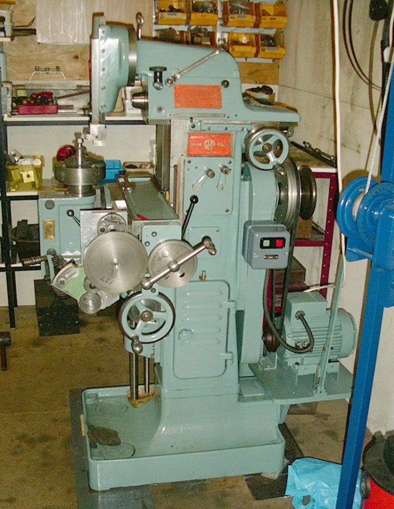
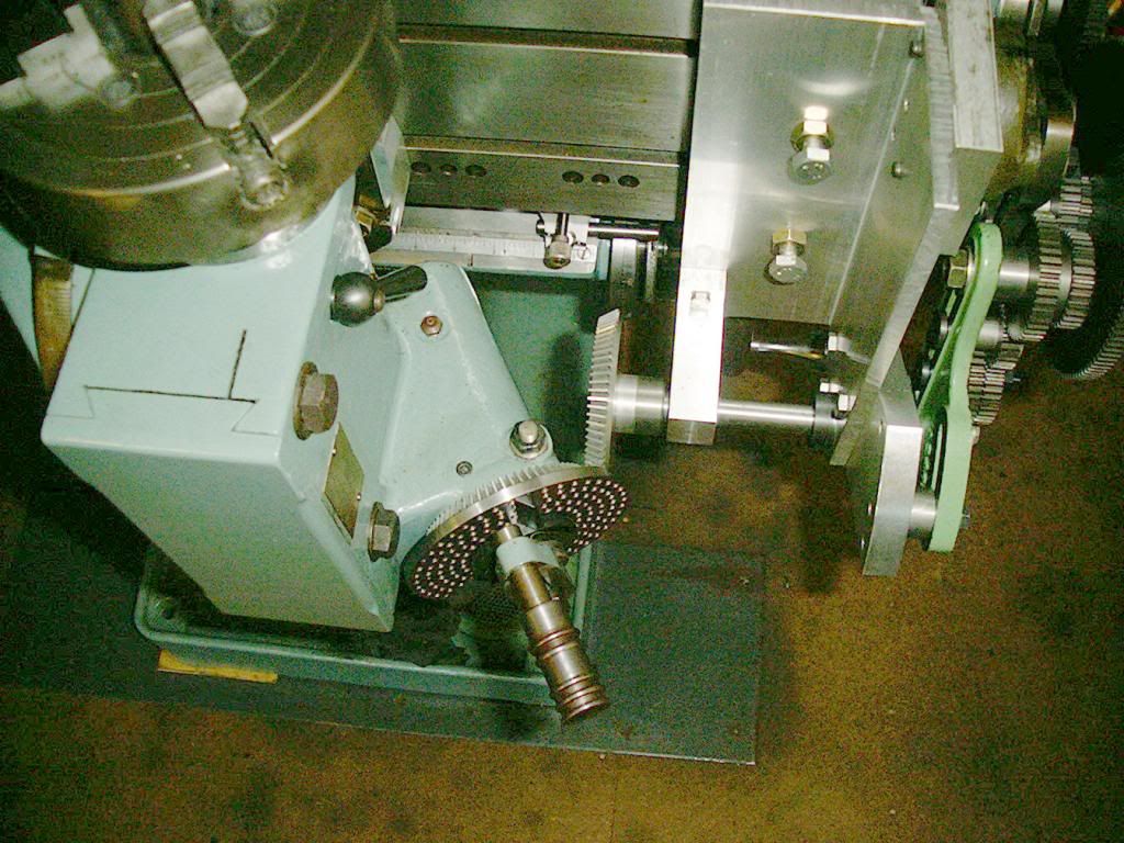
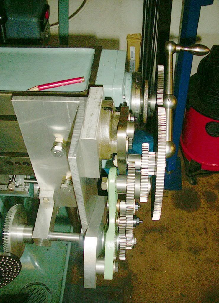
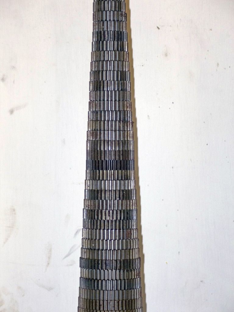
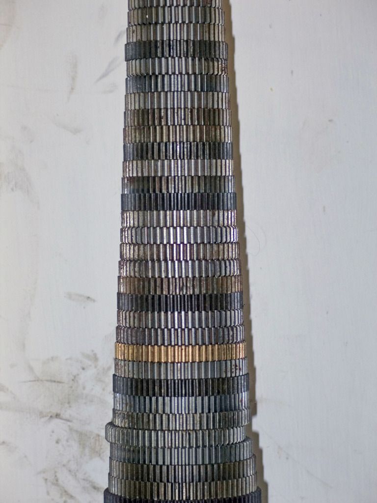
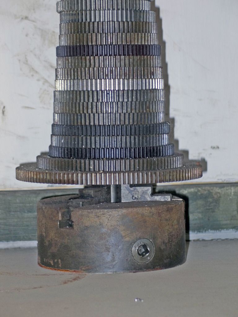
My late father rigged up the Alexander Master Toolmaker milling machine to cut gears by that method. I still have the machine but not used it for cutting gears recently as I also have a conventional Mikron hobbing machine.


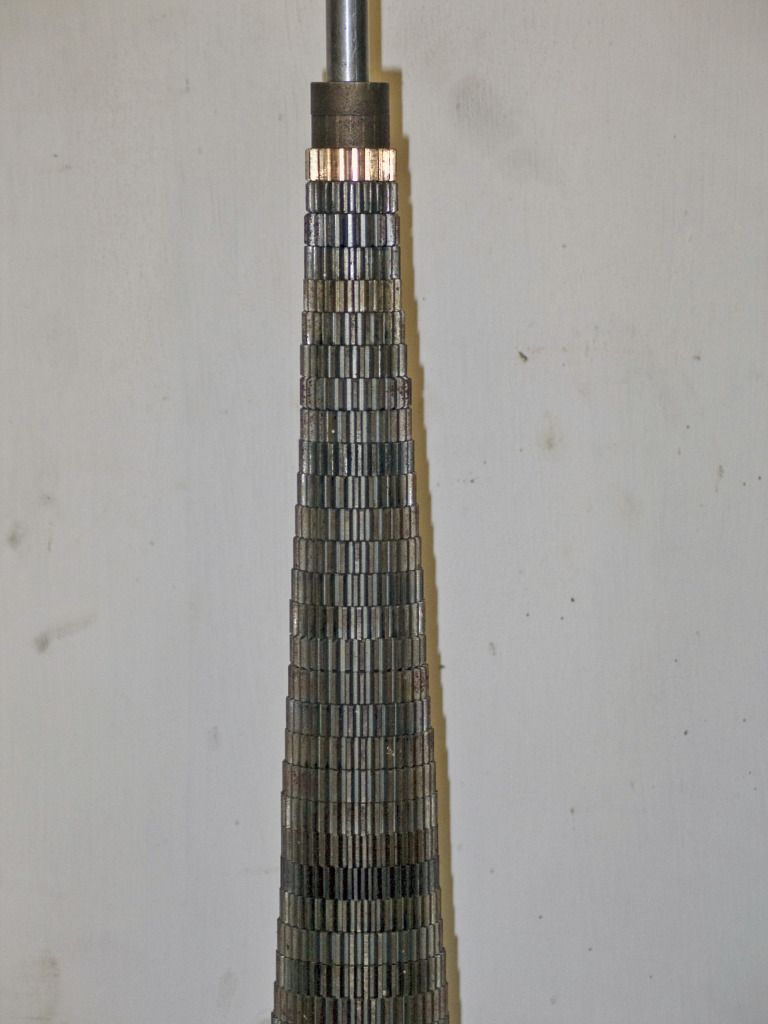
Hope these are of interest. I have a procedure written by my dad for indexing and rolling the blank round for different tooth counts, he cut a full set of change gears for the Myford lathe going up in increments of one tooth, the stack of change gears is about two feet tall.


Phil
 
Found some good info over at Standard Drive Products web site. They have a reference library on line with lots of gear, pulley and belt info. Plenty of formulas, standards and information.

http://sdp-si.com/web/html/reference_library.htm
There's also an excellent treatise for "ESCAP® Ironless Rotor D.C. Micromotors
and Step Motors". They're wonderful motors, small, powerful, Swiss made - and expensive :eek:.
 
hey guys,
Is there a place you can purchase these hobbs? or will I have to make my own? This looks like the easiest way to make gears that I have seen, but I can't find anywhere that makes the hobb, so I don't have to worry about making it myself.
Thanks

I haven't seen them for sale anywhere (and I suspect they're not sold) but this link has all the info on making them and using them, they're really not that hard to make. I've made several gear sets this way that work perfectly on my latest builds. Good luck.
 
Back
Top