Gear formulas question.

Home Model Engine Machinist Forum

Help Support Home Model Engine Machinist Forum:

This site may earn a commission from merchant affiliate links, including eBay, Amazon, and others.
Two things:

1) I have a PDF copy of the Sterling Products/Stock Drive Products Handbook of Gears that I am allowed to distribute (SP/SDP charges you for the paper version -- but even that is cheap). I have not uploaded anything here yet, but it should not be that hard to do (I built my first microcomputer in 1967).

2) I am in the process of redoing my spurgear marcos for General CADD (http://www.GeneralCADD.com -- plug, plug for some friends of mine) to comply with the recent changes in ISO gearing. Part of this, still "in-work." is a document explaining the macro in particular and spur gearing in general. The big thing is that I use a 2-arc approximation of an involute. [AGMA recommends using a 3-arc approximation.] The 2-arc system is reasonable for most hobbyist applications and fairly easy to grind a cutter for using Bob Porter's custom toolbit grinding set-up.

The SP/SDP Handbook of Gears gives you most all of the information in the ($90) AGMA Handbook.
 
bob ward and shred

A real helical hob can not be used on a simple mill.
The gear must be positively driven around as the hob is carving.
The hob is acting as a endless screw but is not supposed to self drive the gear.
Some folks say that after gashing the blank is possible to let the hob drive the blank along but is a recipe for overcutting the spaces.
As stated in the thread, the first round of cuts gives you a segmented (faceted) tooth but if you re-index 1/2 a tooth or as many time as your patient allows you end up with a practical involute.
Plus as shred said the real (helical) hob has a pitch that can only be approximated since is not an integral TPI.
 
I make small brass gears (1/8" to 2") for mechanical instruments and models. The gears need to be what they need to be, so I design them from scratch, choosing the center to center distance and tooth ratio that suits the application. I pick the pressure angle mostly for looks, and I try to use the involute tooth profile because it is easy to form. I don't have to worry about strength or power or many of the other things that real machinists do. I also don't have to worry about economics. I try to make the gears operate as smoothly as possible, with as little backlash and binding as possible. I am able to make low tooth count gears that run without any noticeable cogginess.

The method I have been using could be called "CNC single point fly cutter rack generation". It's nothing new, but I don't see much about it on the Web. It is suited to my needs. I can cut just about every gear I need with one V-shaped fly cutter bit. The bit is cheap (< $2) and easy to sharpen (< 1 minute). I do all of my work on a sewing machine, er, I mean a Sherline Mill (I always get those machines mixed up).

--Justin
 
Burr-cutters and sand-crabs,

I have finally uploaded the Sterling Instrument/Stock Drive Products Handbook of Gears. It turns out if the file extension is "PDF" (as in all capital letters) the file system here rejects it. The extension has to be "pdf" to be valid. As I date to the days when all filenames were all capital letters, it threw me for a loop.

But then, I believe in the square root of -1, so I already know I am an irrational number!
 
Lew_Merrick_PE said:
Burr-cutters and sand-crabs,

I have finally uploaded the Sterling Instrument/Stock Drive Products Handbook of Gears. It turns out if the file extension is "PDF" (as in all capital letters) the file system here rejects it. The extension has to be "pdf" to be valid. As I date to the days when all filenames were all capital letters, it threw me for a loop.

But then, I believe in the square root of -1, so I already know I am an irrational number!
Cool, thanks. Lots of good info there.

I note the 'straight-hob' method is pretty much an approximation of rack-generation, less so proper hobbing.

 
bob ward said:
Is making a DIY spiral hob as simple as combining straight hob techniques with single point threading?

shred said:
Maybe... except the "thread" pitch required usually involves numbers that can't be generated with the typical lathe. I read a discussion on it over on the HSM forum a while back. Seemed like PI was involved. Perhaps a decent approximation can be created. A proper spiral hob ought to be able to make 'correct' gears of any size.

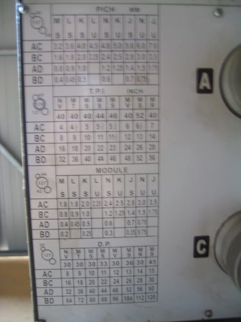
This is the thread cutting table on my generic 14 x 40 lathe. I've used the top half of the table but have not yet learned about the bottom half. Does having the Module and DP settings get me any closer to cutting an accurate spiral hob?

IMG_0023_2-1.jpg
 
bob ward said:
Does having the Module and DP settings get me any closer to cutting an accurate spiral hob?

Yes. The pitch of the hob is the circular pitch of the gear (see http://www.homemodelenginemachinist.com/index.php?topic=7990.0 another thread running alongside this one).

Hence, for a 1 MOD gear, your hob needs to be 3.14mm pitch; for a 1DP (big!) gear it needs to be 3.142 inches pitch (or the inverse of this in tpi). Multiply the metric pitch by your actual MOD to find the corresponding hob pitch. Divide the imperial pitch by your actual DP to find corresponding hob pitch.
 
Been following this with interest. Thanks for all the good info. :bow:
 
Went out to the shop to play tonight. Used some HSS 1/4" stock to make a 40 degree cutter. Grabbed a piece of 1/2" delrin rod. Went through the process of cutting the groves and then milling the flats on the mill and made what looks like a hob. woohoo1

Wanted to kind of get a feel for the process before doing it for real. Still a little foggy on some of the math.

Appreciate all the posts and links. Watched all of Shorty's videos. Downloaded the booklet from our area. Got Marv's program (thanks for another one Marv!!). Read all of Dean's post (several times). Dang, if I hang out here long enough I might even learn something. Don't feel totally clueless now.

Now I need to locate some drill rod.

I do have one question; how do you calculate the width of the flat spot on the end of the gear tooth? I kind of get the spacing and depth part but don't recall seeing this anywhere.
 
black85vette said:
I do have one question; how do you calculate the width of the flat spot on the end of the gear tooth? I kind of get the spacing and depth part but don't recall seeing this anywhere.

B85V,

The tool width can be calculated as follows:

Tool Width at Tip = Circular Pitch/2 - (Tan Pressure Angle x Dedendum x 2)

Difficult to measure accurately. The tool infeed must equal the whole depth and not the working depth of the rack when making the hob. If it's a little wider it will increase the backlash and if it's a little narrower binding may occur.

Hope this helps

Best Regards
Bob
 
Maryak said:
The tool width can be calculated as follows:

Tool Width at Tip = Circular Pitch/2 - (Tan Pressure Angle x Dedendum x 2)

Difficult to measure accurately. The tool infeed must equal the whole depth and not the working depth of the rack when making the hob. If it's a little wider it will increase the backlash and if it's a little narrower binding may occur.

Bob;

Thanks. This is just what I was looking for.

Just to be sure I am understanding; when making the hob, the flat on the end of the hob tips and the tool tip should be the same if you have made the cut to the right depth and your tool is cut correctly. Is that right?
 
black85vette said:
Bob;

Thanks. This is just what I was looking for.

Just to be sure I am understanding; when making the hob, the flat on the end of the hob tips and the tool tip should be the same if you have made the cut to the right depth and your tool is cut correctly. Is that right?

B85V,

I think that is correct because the hob is the reverse of the gap between the gear teeth, so when it cuts the gear blank to full depth the OD/tip of the hob should equal the width at the root diameter of the gear, (the result of the formula I gave you).

Thanks for your help in this, so far your doing all the work and we are learning this together.

Best Regards
Bob
 
Bob; Thanks again. I think it is you guys doing the real work with understanding the theory, figuring out the math and finding all the links. I'm just the lathe monkey cranking out some pieces. :big:

Odd day today. We are in a climate zone that produces tornados. But we also sit between the really cold weather and the warmer weather to the South. So it snows to our North, rains to our South and we get a drizzle that freezed after it falls. It coats the trees, cars, power lines and roads. So our office shut down and sent everyone home to be safe. Not a bad deal, a day in the shop mid-week!

So I ran to the metal supplier and picked up some .5" drill road. Made another 40 degree cutter out of some better material and made a 32 pitch straight hob. Rather than heat treat it I just turned some Delrin and mounted it in the rotary table and made a couple of quick gears. The teeth appear to be a little thin. I think I did not get my depth quite right on the hob.

Anyway, I did make a couple 24 tooth plastic gears that look like they would probably function OK. Not too bad considering two days ago I had no idea how to go about this. It does confirm for me that the method is feasible, not very difficult, and pretty cheap.

As usual, I did come up with another question. This is my first time to use drill rod. Turning it was not too bad. Just a little chatter doing a plunge cut. But then I tried to cut the right angle cuts for the hob teeth and dulled two end mills pretty quickly. Is there something I need to know about working with drill rod?

IMG_2010.jpg
 
putputman said:
I thought the cutting tooth would be on center instead of straddling center. When I cut gears with an involute cutter, I always put the center of the cutter on the center of the gear. I wonder if the profile that he illustrated would look just a little differant if he put his cutter tooth on center of the gear.

It does appear to make a difference. I tried it both ways and putting a cutting tooth on center did not produce a good profile for me.

On another note: On Shorty's website someone asked him why he did not cut the 40 degree notches in the hob on an angle with the compound like cutting a thread. I wondered about that and tried it tonight and had much less chatter and a smoother cut. So I guess I will do it that way from now on. Just have to do a little math to refigure the depth.
 
black85vette said:
On another note: On Shorty's website someone asked him why he did not cut the 40 degree notches in the hob on an angle with the compound like cutting a thread. I wondered about that and tried it tonight and had much less chatter and a smoother cut. So I guess I will do it that way from now on. Just have to do a little math to refigure the depth.

B85V,

If you cut the teeth at an angle you will have to tilt the hob or the gear blank to the same angle, so that the cutter and the blank are at right angles, to get a spur gear out of it. Blogwitch is working on a system to use a spiral hob so it may pay you to ask him the ins and outs of it.

Best Regards
Bob
 
Maryak said:
If you cut the teeth at an angle you will have to tilt the hob or the gear blank to the same angle, so that the cutter and the blank are at right angles, to get a spur gear out of it. Blogwitch is working on a system to use a spiral hob so it may pay you to ask him the ins and outs of it.

Bob;

I didn't explain it well. The end result of the cut stays the same. Rather than plunge straight in I tried advancing the cutter at 20 degrees with the compound while held perpendicular to the work and the carriage not moving. Just like single point threading, the cutter is only cutting on one edge instead of two. At least that's my theory.

Regards,
Rick
 
Rick,

AH HA or Abracadabra ;D

All is revealed and understood. :bow:

Best Regards
Bob
 
Maryak said:
AH HA or Abracadabra ;D

All is revealed and understood. :bow:

Best Regards
Bob

Bob, I just attribute it to the difference in our versions of English. :big:
 
I have been out in the shop cutting some more "practice" hobs out of aluminum and think I have all my dimensions where I want them for a 32 pitch hob. Drew up 5 and 6 tooth .5" diameter profiles in CAD. I think the 6 tooth will not leave enough on each tooth. The flat spot on top ends up about .015" the 5 tooth is about .060"

Got "Gears and Gear Cutting" by Ivan Law in today. Looks like lots of good info for not too much money.

Here are the profiles for the cutters.


cutter.jpg
 

Latest posts

Back
Top