Fusion360 CAM Tips and Tricks

Home Model Engine Machinist Forum

Help Support Home Model Engine Machinist Forum:

This site may earn a commission from merchant affiliate links, including eBay, Amazon, and others.

Eccentric

Well-Known Member
HMEM Supporting Member
Joined
Dec 29, 2020
Messages
326
Reaction score
747
Location
Southern California
I've been using Fusion360 CAM for a little while and on the whole am very pleased with its capability. But it often seems that I have to finagle ways to fool it into doing what I want. I am creating a video series on some of the tricks and tips I have learned, and am looking for other ideas for video topics. If there is a CAM challenge you have been wrestling with, let me know and I will take a look to see if I can figure out a way for Fusion360 to do what we want.


If you have any Fusion360 tips or tricks of your own, feel free to post them here.
 
Can fusion import and modify an stl file? I have files for a model t that I want to modify, scale down, cut in half or 3 pieces so I can 3d print them. They are for a future project and this is the only hold up. I know I couldn't draw them from scratch.
 
Steve,

STL files describe the outside surface of an object by defining it in a bunch of conntected triangles, that is, an STL file is not a solid body format. Fusion360 can import and scale an stl file, but the usual way of cutting an STL file in half is in the 3D printer slicer. Now most CAD programs (including Fusion360) can take an STL file and convert them into a solid body that can then be manipulated, cut in half for example, or add other features, such as tabs or holes. You would then convert it back to an STL file and slice it for your 3D printer.

Everything you describe wanting to do can be done in your 3D printer slicer (if I understand what you are trying to do). Fusion360 can be used to scale your STL file, then export it if you like. Slicers can scale, cut an STL in half, then re export them as STL files, but Fusion360 no longer has a slicer.

I use Fusion360 CAM for creating tool paths for my home made CNC router.
 
You should not need to modify the part with those extra pieces to keep it attached to the stock.

If you use the 2D contour path then all you need to do is position a couple of tabs which is a feature of the 2D contour geometry dropdown, here I have use two 5mm wide tabs and made them slightly shallower than the part's thickness. If your machine is not good at plunging then there is the option for triangular tabs so the cutter ramps up and then down the other side of the tab

tabs 2.JPG

tabs1.JPG

the 2D contour also allows for you to specify a full depth finishing pass rather than having to do a separate one.

Having said that I'm not a fan of that approach to machining parts like this. I would drill the two hole sin a piece of stock and then screw it to a scrap piece of material that has used those hole locations to drill and tap the hole son the CNC or you can do that on the manual mill and them clock in the tooling block on the CNC.

Then use an adaptive path to remove the waste using a full depth cut which saves wearing the end of the mill. Finally finish with a 2D contour at full depth.

This video shows how much quicker the adaptive/contour is comparted with a path that would have cut the part from a larger sheet. Also no attachment tabs to be cleaned up

 
Last edited:
I like the fact that the tabs are shorter and there is less material to cut through and less filing work required to clean up the final part.

I like your final approach for two reasons, as you stated adaptive is better on the tool, and I don't like cutting slots. And of course, no tabs!

thanks
 
I'd probably make them shorter than that, typically 1/3rd the thickness of the material particularly if I could have got a tab on the other side

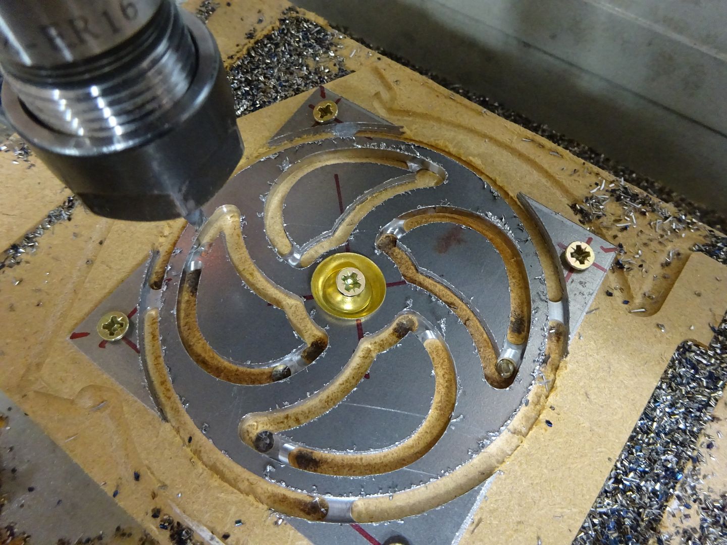
This one I screwed the stock down at the corners, used a Pocket path to do the central hole and then added an additional screw in teh middel before using 2D contour with tabs first for the spoke cut outs and then another for the OD

tabs3.JPG


DSC04502.JPG
 
Steve,

Everything you describe wanting to do can be done in your 3D printer slicer (if I understand what you are trying to do).

The files need to be converted so the part can be modified. The tabs that are used to mount the fender to the car needs to be added and some other cleanup work needs to be done. They will be about 2 feet long so I will need to print in 3 pieces. Might get lucky and get it in 2 pieces.

Fender_Rear.jpg
 
Steve,

I use soildworks for my CAD and I can do what you need, if you want to PM with your files and a sketch with what you would like, I can generate the STL files for you. I would import STL as a "solid body", then add the tabs as you specify. Finally I would cut the part up into smaller pieces and save each as an STL. I could also scale if need be.
 
You should not need to modify the part with those extra pieces to keep it attached to the stock.

If you use the 2D contour path then all you need to do is position a couple of tabs which is a feature of the 2D contour geometry dropdown, here I have use two 5mm wide tabs and made them slightly shallower than the part's thickness. If your machine is not good at plunging then there is the option for triangular tabs so the cutter ramps up and then down the other side of the tab

View attachment 142138
View attachment 142137
the 2D contour also allows for you to specify a full depth finishing pass rather than having to do a separate one.

Having said that I'm not a fan of that approach to machining parts like this. I would drill the two hole sin a piece of stock and then screw it to a scrap piece of material that has used those hole locations to drill and tap the hole son the CNC or you can do that on the manual mill and them clock in the tooling block on the CNC.

Then use an adaptive path to remove the waste using a full depth cut which saves wearing the end of the mill. Finally finish with a 2D contour at full depth.

This video shows how much quicker the adaptive/contour is comparted with a path that would have cut the part from a larger sheet. Also no attachment tabs to be cleaned up


The approach using the holes to fixture the parts is the best option in my opinion. As long as there are holes big enough to use matching screws and as long as there are enough holes to secure the complete part :cool:.
Tabs are usually the next best way to go.
Tabs in "real metal" often make the cutter deflect in the plunge, it is leaving ugly machining marks on the side. I had good experience with using the ramp option instead of a vertical plunge, it is much easier on the cutter. You will find it on the link tab of the tool path. And as described by jasonb, do a separate finish pass of some sort to deal with the machining marks.ramping.jpg
rampsimulation.jpg

Greetings Timo
 
You should not need to modify the part with those extra pieces to keep it attached to the stock.


I need to modify the file to make the part usable not add tabs for printing. There is an 1.5 inch strip on the inside of the fender that runs almost front to back. That feature is not present in the files I have and without them they will not be able to be mounted to the car.

20221105_140144.jpg


12256.jpeg
 
  • Like
Reactions: Zeb
Steve, I was referring to what was in Eccentric's video. He showed how to do something without knowing that F360 has a far simpler and better way of doing it.
 
This is a Fusion360 CAM focused video exploring a few tricks including: using Machining Operation Templates, Reusing complete CAM Setups, and using the secret CAD capability inside Fusion360 CAM. We will make and modify our own manufacturing model without touching the original CAD model. We will end up with all the tool paths to machine both of the aluminum plates to complete our Wallaby 30cc Timing Case. The Timing Case houses the timing gear train, which turns the camshaft at half the speed of the crankshaft.


The accompanying construction video is here:


Interesting:

Any reason why the backplate and the body are not one part? If you CNC anyway, you could make assembly easier? More chips, more better.....
Haha....
If there is a CAM challenge you have been wrestling with, let me know and I will take a look to see if I can figure out a way for Fusion360 to do what we want.
If you have any Fusion360 tips or tricks of your own, feel free to post them here.
Yes, i have a Cam challenge, that I could not get to work. if you care to have a play.
I put the fusion, thing into the zip, because the forum does not allow the file type.
There are three setups in the file intended to do basically the same.
1st is using 3d pockets , it did more or less does what I wanted. (I already cut my parts yesterday, so right now this is just a theoretical exercise :cool: )
The 2nd setup I tried to use the 2d pocket operations with "rest machining"
  • The pocket with the smallest Endmill tries to plunge outside the part into the stock, which would (did) brake the tool, (is not so clever). I cannot convince it to enter from the inside. (tried to fiddle with entry positions and predrill positions; no success.
The 3rd setup I tried to use 2d adaptives and the rest machining.
  • Leaving too much Material in strange positions. I do not understand how the "rest machining" needs to be tweaked in order ot do it righ

Maybe you have a play, in case you are bored.

Greetings Timo
 

Attachments

  • sideplate v3.zip
    818.6 KB
Timo, you should have watched the simulation more closely it shows the crash as the tool plunges straight down in red;)

I don't tend to use pocket that much so below is what I came up with.

The reason I don't us epocket that much is you can end up with some large tool engagement, even your setup 1 has that 2mm tool cutting full width and 2,5mm beep which is quite a loading, the adaptive will keep tool engagement down.

Your pocket clearing cuts are also full depth which combined with those full width cuts could affect the quality of teh bottom of teh recess.

Likewise your finish contour i sgoing through different amounts of radial material that has been left and as it is just one pass you could get different amounts of tool deflection as the thicknes sof cut changes.

First three ops can stay the same but move the reaming up so it is done after drillinh

-Do the spot drilling as you have first as the 3mm spot drill won't work on that internal corner location if done later.
-Drill holes as you have
- Ream holes as you have

Then the bit I would do differently

- Do a 3D adaptive with the 4mm dia tool selecting the bottom of the recess as the geometry and set "tool ctr on boundry" as this will ensur eit does not enter from outside the area, leave 0.3 radial and axial
- Do a 3D adaptive with the 2mm tool, same geometry and same stock to leave. But click rest machining and tick "from previous" that way it only machines what the previous cutter could not get at in the corners and where the space is too narrow.
- 3D Horizontal with same 0.3 radial but zero axial stock to leave which will finish the bottom of the recess.
=2D contour with 2 roughing passes and one finish pass all of 0.1mm as it's quite a small 2mm dia tool to finish sides of recess. If it were a larger cutter I would do one rough at 0.2mm and one finish at 0.1mm and that can go to a height of 2 x diameter before I think about multiple depths.

File in my dropbox (Now edited) to download and see what I did
 
Last edited:
Greg, I don't tend to use the "secret" CAD in F360. As I design in Alibre the parts I export from there to use F360 CAM for are already my "manufacturing part" and if they need altering I'll just use the design section of 360 to make any changes and that won't affect my original part as that is still safe and sound in Alibre. Only really useful if you do your CAD in F360 too so that the part file doe snot get altered.
 
Timo, you should have watched the simulation more closely it shows the crash as the tool plunges straight down in red;)

I don't tend to use pocket that much so below is what I came up with. The reason I don't us epocket that much is you can end up with some large tool engagement, even your setup 1 has that 2mm tool cutting full width and 2,5mm beep which is quite a loading, the adaptive will keep tool engagement down.

-Do the spot drilling as you have first as the 3mm spot drill won't work on that internal corner location if done later.
-Drill holes as you have
- Ream holes as you have

- Do a 3D adaptive with the 4mm dia tool selecting the bottom of the recess as the geometry and set "tool ctr within boundry" as this will ensur eit does not enter from outside the area, leave 0.3 radial and axial
- Do a 3D adaptive with the 2mm tool, same geometry and same stock to leave. But click rest machining and tick "from previous" that way it only machines what the previous cutter could not get at in the corners and where the space is too narrow.
- 3D Horizontal with same 0.3 radial but zero axial stock to leave which will finish the bottom of the recess
=2D contour with 2 roughing passes and one finish pass all of 0.1mm as it's quite a small 2mm dia tool to finish sides of recess

File in my dropbox to download and see what I did
Hello,

2.5 mm depth with a 2 mm cutter in steel and full engagement is not clever.
I knew that before yesterday, but hope dies last (the 2mm endmill first) Aah you can slow the damn thing down! Or not?
Since yesterday I know once more that slowing down is not working. (do not do this at home).
Tried to download from drop box, worked but I cannot see changes looks like the original file.

Greetings Timo
 
Uploaded the original, try this which should be my version

I left the feed rates for the cutters as you had set them, it is more the machining paths that I wanted to show
 
Jason B,

I am with you on an not using fusion360 manufacturing models that much. I design in solidworks and have different configurations of my parts for different machining operations. This is primariy becasue I am WAY more proficeint and feel more comfortable in the solidworks environment. But there are a few times, such as the example in my video where I drew a simple line to reorient the stock, that Fusion360 manufacturing models are helpful. It can be a pain to bounce back and forth between solidworks and Fusion360 as I have to re-export the IGS model, import and copy over the setup, all for a simple tweak of my "solidworks manufacturing configuration". Time will tell if I use the Fusion360 manufacturing model feature more.

I really liked your explaination to Timo,

Greg
 
Greg, I agree it's a pain to go back and forth between two programs.

But what I said was that if I do alter something in F360 I simply go to design top left and do the alteration there rather than use the manufacturing model option. This pic shows the same line being drawn in Design. So it's just a case of clicking between Design and manufacture and you don't then end up with a second file.

f360 design.JPG
 

Latest posts

Back
Top