Tel--Absolutely loverly!!!!
You are using an out of date browser. It may not display this or other websites correctly.
You should upgrade or use an alternative browser.
You should upgrade or use an alternative browser.
Flyball governor plans
- Thread starter Brian Rupnow
- Start date

Help Support Home Model Engine Machinist Forum:
This site may earn a commission from merchant affiliate
links, including eBay, Amazon, and others.
Tel--If you can drag the drawings out and post them or email them to me, that would be just great. What kind of steam/air supply valve did it operate??--a sliding valve or a butterfly valve. Did you find that it was effective and actually governed the speed of what you were running with it?---Brian
SignalFailure
Well-Known Member
- Joined
- Jan 1, 2008
- Messages
- 366
- Reaction score
- 3
tel said:That reminds me, I forgot all about digging out the drawings. To give you an idea, the bevel gears are about 3/8" diameter, and yes, I cut them on the Myford - hand planing with the topslide
Argghh the dreaded gears - my hands have only just recovered! ;D

$89.99
Outdoor Wood Boiler Water Treatment Rust Inhibitor- AmTech 300 & Test Kit
Alternative Heating & Supplies
![DreamPlan Home Design and Landscaping Software Free for Windows [PC Download]](https://m.media-amazon.com/images/I/51kvZH2dVLL._SL500_.jpg)
$0.00
DreamPlan Home Design and Landscaping Software Free for Windows [PC Download]
Amazon.com Services LLC

$519.19
$699.00
FoxAlien Masuter Pro CNC Router Machine, Upgraded 3-Axis Engraving All-Metal Milling Machine for Wood Acrylic MDF Nylon Carving Cutting
FoxAlien Official

$24.99
$34.99
Bowl Sander Tool Kit w/Dual Bearing Head & Hardwood Handle | 42PC Wood Sander Set | 2" Hook & Loop Sanding Disc Sandpaper Assortment | 1/4" Mandrel Bowl Sander for Woodturning | Wood Lathe Tools
Peachtree Woodworking Supply Inc

$45.99
Sunnytech Mini Hot Air Stirling Engine Motor Model Educational Toy Kits Electricity HA001
stirlingtechonline

$99.99
AHS Outdoor Wood Boiler Yearly Maintenance Kit with Water Treatment - ProTech 300 & Test Kit
Alternative Heating & Supplies

$39.58
$49.99
Becker CAD 12 3D - professional CAD software for 2D + 3D design and modelling - for 3 PCs - 100% compatible with AutoCAD
momox Shop

$39.99
$49.99
Sunnytech Low Temperature Stirling Engine Motor Steam Heat Education Model Toy Kit For mechanical skills (LT001)
stirlingtechonline

$94.99
$109.99
AHS Woodmaster 4400 Maintenance Kit for Outdoor Wood Boiler Treatment
Alternative Heating & Supplies

$17.54
$18.99
Product-Led SEO: The Why Behind Building Your Organic Growth Strategy
The Quality Books

$180.50
$190.00
Genmitsu CNC 3018-PRO Router Kit GRBL Control 3 Axis Plastic Acrylic PCB PVC Wood Carving Milling Engraving Machine, XYZ Working Area 300x180x45mm
SainSmart Official

$29.95
Competition Engine Building: Advanced Engine Design and Assembly Techniques (Pro Series)
Amazon.com Services LLC
Brian, please tell me where you found the dimensioned drawing of the governor.
There is a story here- I have that drawing somewhere in one of my books. When I was doing the first show flyer for the New England Model Engineering Society [url]www.neme-s.org [/url] I found it, scanned it, and used it in the flyer. It later became essentialy the logo of the club- its on our Shirts, our show banners, newsletter and Ive even made engraved name plates several of us use at shows.
I want to make a model of it, but I can only find the scanned drawing, from which I stripped the dimensions to make it simpler for the logo.
dsquire
Well-Known Member
- Joined
- Mar 18, 2008
- Messages
- 980
- Reaction score
- 15
Ron
Thanks for posting the link to www.neme-s.org. I have been over there for several hours and I know that I have barely scratched the surface. Steam, all types of engines and tractors, machinery, antique tools, Jet model aircraft any many many more. If anybody hasn't clicked on it yet I would advise them to if they like that type of thing and I think most on this forum do. I know that I have book marked it so that I can go back.
Thanks again Ron
cheers
Don
Tel---A question for you. Did you find the flyball governor which you built to be effective in governing the speed of the engine which you put it on. And--how many cylinders was the engine it was controlling, and what bore and stroke?--A lot of questions I know, but stuff I need to know before I embark on a build if I make one of these for myself. Thanks, Brian
tel
Well-Known Member
- Joined
- Feb 8, 2008
- Messages
- 3,293
- Reaction score
- 45
Well, yes, the governor worked quite well, but as I said, I did simplify the innards of it - just a simple plug moving up & down in a bore and covering, uncovering, the steam passage.
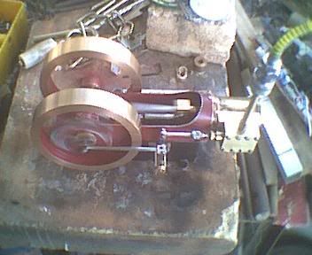
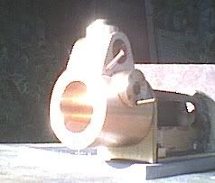
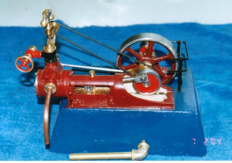
The engine in question is Jesse Livingston's Rocking Valve Mill Engine - 1" bore, 1 1/8" stroke - the cylinder on the is quite a compliacted piece, and was a lot trickier to fabricate - still, the finished product was well worth the effort.
Here's a couple of pics before and after silver soldering the fabrication, but befor clean up. Them porcupine quills are little bits of 1/16" brazing rod that were used to hols everything together and got cut off and disappeared during clean up.
Bottom pic is the complete engine


Thanks Terry.---Brian
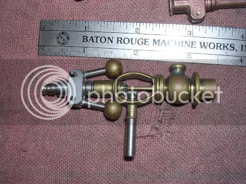
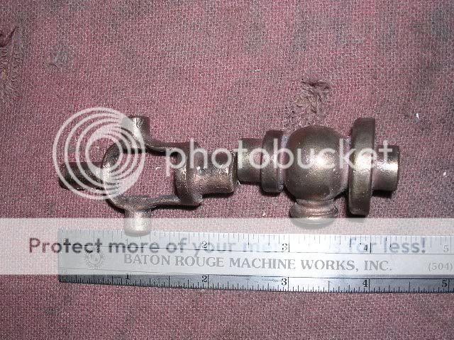
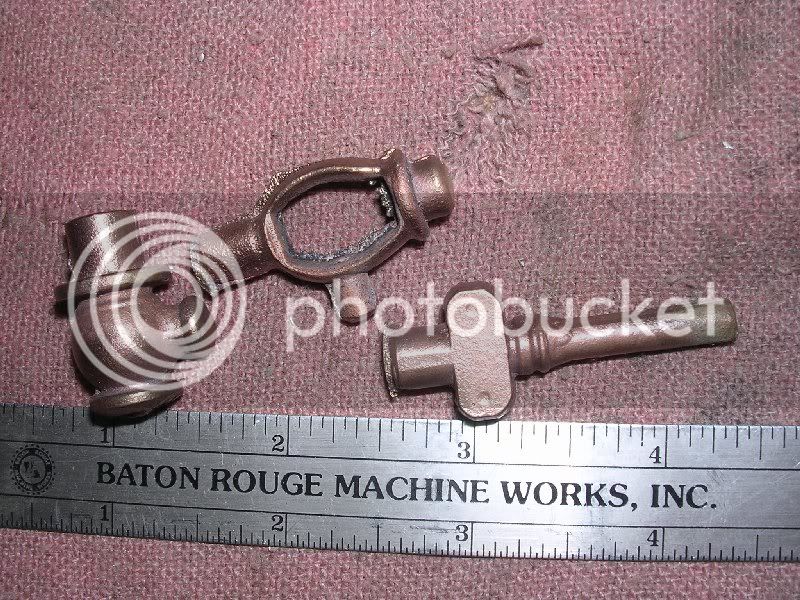
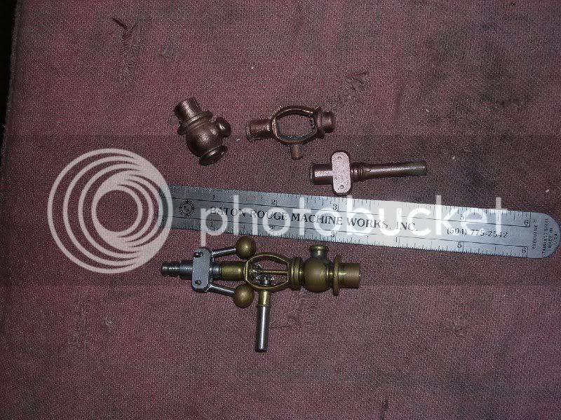
Look what I found!!! This is a casting kit by Art Dekalb in New York. It comes in two sizes, one with 3/8" balls and one with 1/2" balls. of course the one in the picture has been fully finished, but Art only sells the castings, apparently. I am currently wheeling and dealing with him, trying to get price and delivery.---Brian

I've been thinkin'---And thats a VERY dangerous thing---As Granny used to say---"Idle hands are the Devils workshop"---
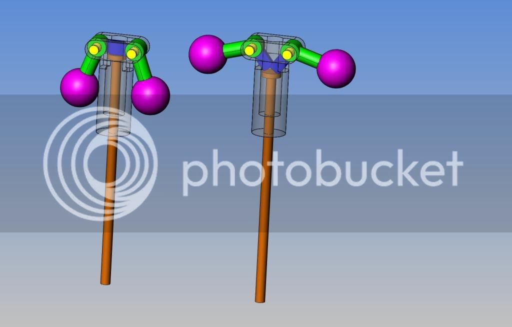

Very Dangerous---
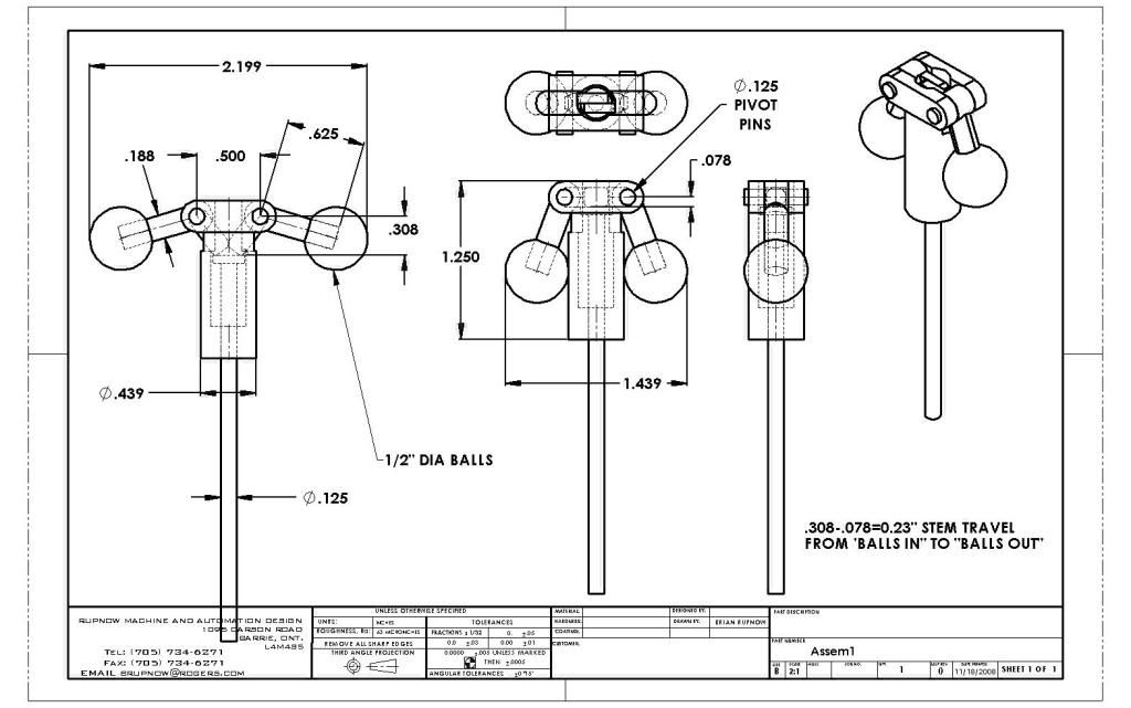

tel
Well-Known Member
- Joined
- Feb 8, 2008
- Messages
- 3,293
- Reaction score
- 45
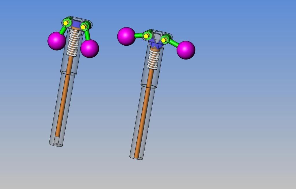
You got it Brian - 'cept you didn't show the spring!
Now picture the end of the spindle carrying a piston of slightly larger diameter, working in a bore to cover the steam inlet as it descends from the action of the balls. Much simpler than the version I sent you, and the way I did mine.
Now picture the end of the spindle carrying a piston of slightly larger diameter, working in a bore to cover the steam inlet as it descends from the action of the balls. Much simpler than the version I sent you, and the way I did mine.
Tel---I didn't forget the spring.--Its just that springs are a miserable thing to model. I just got an email from the guy in New york. His "Kit" sells for $20.00 U.S. plus $4.50 handling. Seems like a reasonable deal to me. He said that they come complete with sets of drawings. I don't see the brass balls in his "Kit" and I guess the shaft and gears aren't there either. If I don't have any real work tomorrow (which isn't looking too probable) I will go ahead and finish my design. I have a design here for the governor used on a Stewart model, which has no gears, just a pulley on the bottom of the ball bracket. It is driven by a 90 degree twisted belt off the main driveshaft, which would be ideal to work with my horizontal twin that I just finished.


Tel--Only for you, I put the spring in--- ;D ;D

Similar threads
- Replies
- 75
- Views
- 13K


